Page 129 of 1690

42±29
AVENSIS REPAIR MANUAL (RM1018E)
16. INSTALL RELEASE FORK SUPPORT
(a) Install the relea")
D26819
EXCEPT 1CD±FTV Engine Type:
1CD±FTV Engine Type:
Release Hub Grease
±
CLUTCH CLUTCH UNIT (MTM)
42±29
AVENSIS REPAIR MANUAL (RM1018E)
16. INSTALL RELEASE FORK SUPPORT
(a) Install the release fork support to the transaxle assy.
Torque:
1ZZ±FE/3ZZ±FE/1CD±FTV Engine Type: 37 N �m (375 kgf �cm, 27 ft �lbf)
1AZ±FSE/1AZ±FE Engine Type: 47 N �m (480 kgf �cm, 35 ft �lbf)
17. INSTALL RELEASE BEARING HUB CLIP
18. INSTALL CLUTCH RELEASE FORK SUB±ASSY
(a) Apply the release hub grease to the release fork and re-lease bearing assy contact, release fork and push rod
contact, and release fork pivot points.
Sealant:
Part No. 08887±01806, RELEASE HUB GREASE or
equivalent
(b) Install the release fork to the release bearing assy.
19. INSTALL CLUTCH RELEASE BEARING ASSY
(a) Apply the clutch spline grease to the input shaft spline. Sealant:
Part No. 08887±01706, CLUTCH SPLINE GREASE or equivalent
(b) Install the bearing to the release fork, and then install them to the tr\
ansaxle assy.
NOTICE:
After the installation, move the folk forward and backward to check that\
the release bearing slides
smoothly.
20. INSTALL CLUTCH RELEASE FORK BOOT
21. INSTALL MANUAL TRANSAXLE ASSY
(a)1ZZ±FE, 3ZZ±FE Engine (See page 41±15)
(b)1AZ±FE, 1AZ±FSE Engine (See page 41±24)
(c)1CD±FTV Engine (See page 41±33)
Page 131 of 1690
69064±02
B67409
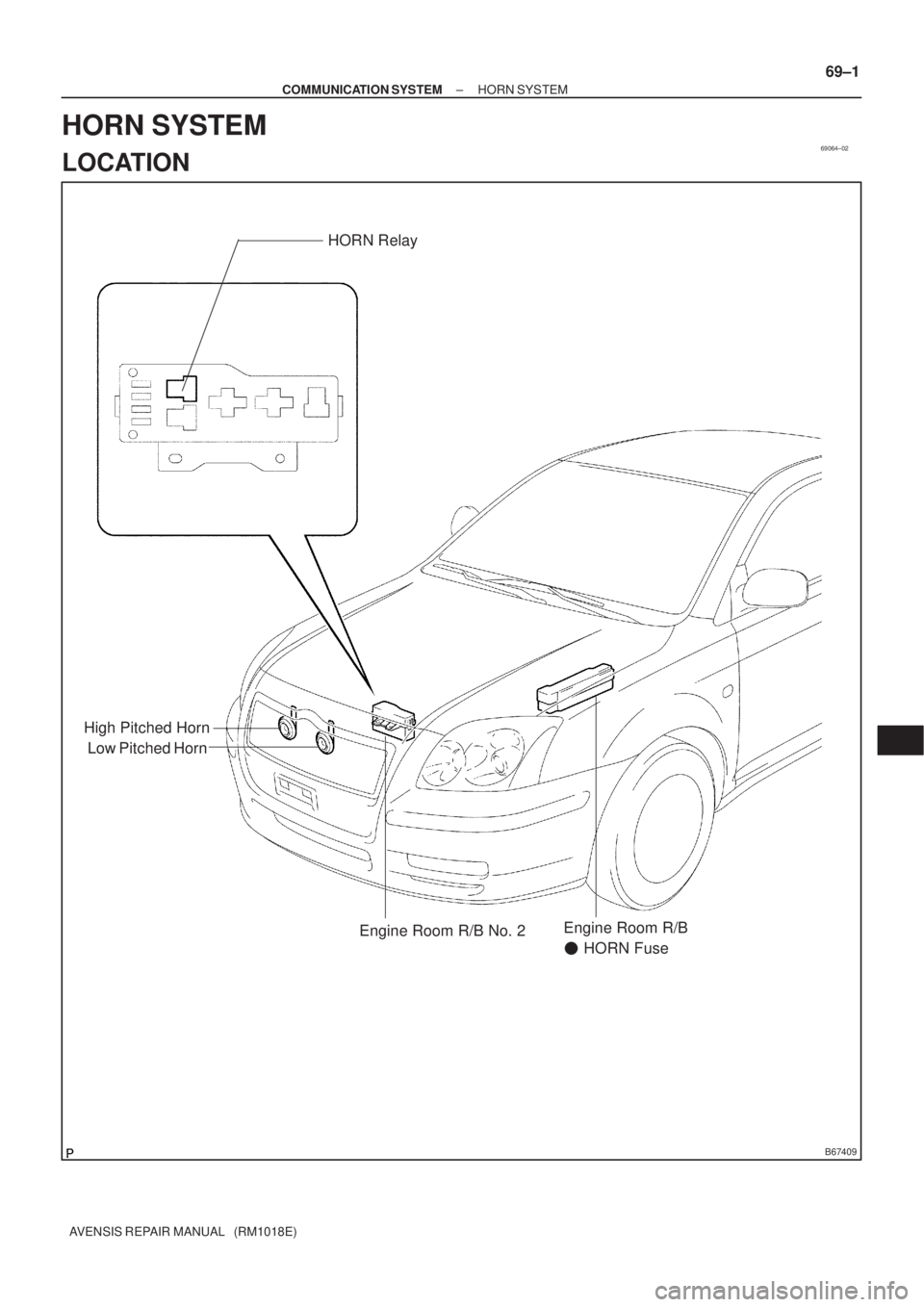
Low Pitched HornHORN Relay
High Pitched Horn
Engine Room R/B No. 2Engine Room R/B
� HORN Fuse
± COMMUNICATION SYSTEMHORN SYSTEM
69±1
AVENSIS REPAIR MANUAL (RM1018E)
HORN SYSTEM
LOCATION
Page 133 of 1690
69066±02
B67416
B67417
B68374
21
5
3
± COMMUNICATION SYSTEMHORN SYSTEM
69±3
AVENSIS REPAIR MANUAL (RM1018E)
INSPECTION
1. INSPECT LOW PITCHED HORN ASSY
(a) Check operation of the horn.
Standard:
Measurement ConditionSpecified Condition
Battery positive (+) �Terminal 1
Battery positive (±) �Horn bodyHorn sounds
If the result is not as specified, replace the horn assy.
2. INSPECT HIGH PITCHED HORN ASSY
(a) Check operation of the horn.
Standard:
Measurement ConditionSpecified Condition
Battery positive (+) �Terminal 1
Battery positive (±) �Horn bodyHorn sounds
If the result is not as specified, replace the horn assy.
3. INSPECT HORN RELAY ASSY
(a) Remove the HORN relay from the engine room R/B No.
2.
(b) Check the horn relay resistance.
Standard:
Tester ConnectionSpecified Condition
10 k� or higher
3 ± 5Below 1 �
(When battery voltage is applied to terminals 1 and 2)
If the result is not as specified, replace the relay assy.
Page 135 of 1690

16±17
AVENSIS REPAIR MANUAL (RM1018E)
COOLING FAN SYSTEM (1AZ±FE)
ON±VEHICLE INSPECTION
HINT:
It is normal that the cooling fan sometime rotates w")
1600R±13
± COOLINGCOOLING FAN SYSTEM (1AZ±FE)
16±17
AVENSIS REPAIR MANUAL (RM1018E)
COOLING FAN SYSTEM (1AZ±FE)
ON±VEHICLE INSPECTION
HINT:
It is normal that the cooling fan sometime rotates when the ignition switch is turned from ACC to ON.
1. CHECK COOLING FAN OPERATION WITH LOW TEMPERATURE (Below 77�C (171�F))
(a) Turn the ignition switch ON.
(b) Check that the cooling fan stops.
If not, check the cooling fan relay and engine coolant temperature sensor, and check for disconnection of
connectors or wire break between the cooling fan relay and engine coolant temperature sensor.
(c) Disconnect the engine coolant temperature sensor connector.
(d) Check that the cooling fan rotates.
If not, check the fuses, cooling fan relay, ECM and cooling fan, and check for a short circuit between the
cooling fan relay and engine coolant temperature sensor.
(e) Reconnect the engine coolant temperature sensor connector.
2. CHECK COOLING FAN OPERATION WITH HIGH TEMPERATURE (Above 95.5�C (204�F))
(a) Start the engine, and raise coolant temperature to above 95.5�C (204�F).
HINT:
Coolant temperature is the detected value by the engine coolant temperature sensor on the water outlet.
(b) Check that the cooling fan rotates.
If not, replace the engine coolant temperature sensor.
3. INSPECT COOLING FAN
(a) Disconnect the cooling fan connector.
(b) Connect battery and ammeter to the cooling fan connector.
(c) Check that the cooling fan rotates smoothly, and check the reading on the ammeter.
Standard amperage:
5.2 to 8.2 A at 20�C (68�F) (M/T)
8.3 to 11.3 A at 20�C (68�F) (A/T)
(d) Reconnect the cooling fan connector.
4. INSPECT COOLING FAN No.2 (With Air Conditioner)
(a) Disconnect the cooling fan connector.
(b) Connect battery and ammeter to the cooling fan connector.
(c) Check that the cooling fan rotates smoothly, and check the reading on the ammeter.
Standard amperage:
5.2 to 8.2 A at 20�C (68�F) (M/T)
8.3 to 11.3 A at 20�C (68�F) (A/T)
(d) Reconnect the cooling fan connector.
Page 137 of 1690

16±29
AVENSIS REPAIR MANUAL (RM1018E)
COOLING FAN SYSTEM (1AZ±FSE)
ON±VEHICLE INSPECTION
HINT:
It is normal that the cooling fan sometime rotates")
1600R±12
± COOLINGCOOLING FAN SYSTEM (1AZ±FSE)
16±29
AVENSIS REPAIR MANUAL (RM1018E)
COOLING FAN SYSTEM (1AZ±FSE)
ON±VEHICLE INSPECTION
HINT:
It is normal that the cooling fan sometime rotates when the ignition switch is turned from ACC to ON.
1. CHECK COOLING FAN OPERATION WITH LOW TEMPERATURE (Below 83�C (181�F))
(a) Turn the ignition switch ON.
(b) Check that the cooling fan stops.
If not, check the cooling fan relay and engine coolant temperature sensor, and check for disconnection of
connectors or wire break between the cooling fan relay and engine coolant temperature sensor.
(c) Disconnect the engine coolant temperature sensor connector.
(d) Check that the cooling fan rotates.
If not, check the fuses, cooling fan relay, ECM and cooling fan, and check for a short circuit between the
cooling fan relay and engine coolant temperature sensor.
(e) Reconnect the engine coolant temperature sensor connector.
2. CHECK COOLING FAN OPERATION WITH HIGH TEMPERATURE (Above 100�C (212�F))
(a) Start the engine, and raise coolant temperature to above 100�C (212�F).
HINT:
Coolant temperature is the detected value by the engine coolant temperature sensor on the water outlet.
(b) Check that the cooling fan rotates.
If not, replace the engine coolant temperature sensor.
3. INSPECT COOLING FAN
(a) Disconnect the cooling fan connector.
(b) Connect battery and ammeter to the cooling fan connector.
(c) Check that the cooling fan rotates smoothly, and check the reading on the ammeter.
Standard amperage:
5.2 to 8.2 A at 20�C (68�F) (M/T)
8.3 to 11.3 A at 20�C (68�F) (A/T)
(d) Reconnect the cooling fan connector.
4. INSPECT COOLING FAN No.2 (With Air Conditioner)
(a) Disconnect the cooling fan connector.
(b) Connect battery and ammeter to the cooling fan connector.
(c) Check that the cooling fan rotates smoothly, and check the reading on the ammeter.
Standard amperage:
5.2 to 8.2 A at 20�C (68�F) (M/T)
8.3 to 11.3 A at 20�C (68�F) (A/T)
(d) Reconnect the cooling fan connector.
Page 139 of 1690

16±41
AVENSIS REPAIR MANUAL (RM1018E)
COOLING FAN SYSTEM (1CD±FTV)
ON±VEHICLE INSPECTION
1. CHECK COOLING FAN OPERATION WITH LOW TEM")
1606N±03
A57065
21
��
± COOLINGCOOLING FAN SYSTEM (1CD±FTV)
16±41
AVENSIS REPAIR MANUAL (RM1018E)
COOLING FAN SYSTEM (1CD±FTV)
ON±VEHICLE INSPECTION
1. CHECK COOLING FAN OPERATION WITH LOW TEMPERATURE (Below 83�C (181�F))
(a) Turn the ignition switch ON.
(b) Check that the cooling fan stops.
(c) Disconnect the temperature detect switch connector.
(d) Connect the terminals on the temperature detect switch connector.
(e) Check that the cooling fan rotates.
If not, check the fuses, cooling fan relay and cooling fan, and check for a open circuit between the cooling
fan relay and temperature detect switch.
(f) Reconnect the temperature detect switch connector.
2. CHECK COOLING FAN OPERATION WITH HIGH TEMPERATURE (Above 93�C (199�F))
(a) Start the engine, and raise coolant temperature to above 93�C (199�F)
HINT:
Coolant temperature is the detected value by the temperature detect switch on the radiator lower tank.
(b) Check that the cooling fan rotates.
If not, replace the temperature detect switch.
3. INSPECT COOLING FANS
(a) Disconnect the cooling fan connector.
(b) Connect battery and ammeter to the cooling fan connec-
tor.
(c) Check that the cooling fan rotates smoothly, and check
the reading on the ammeter.
Standard amperage:
Approx. 13.2 A at 20�C (68�F)
(d) Reconnect the cooling fan connector.
Page 142 of 1690

16±5
AVENSIS REPAIR MANUAL (RM1018E)
COOLING FAN SYSTEM (1ZZ±FE/3ZZ±FE)
ON±VEHICLE INSPECTION
HINT:
It is normal that the cooling fan som")
1600R±14
± COOLINGCOOLING FAN SYSTEM (1ZZ±FE/3ZZ±FE)
16±5
AVENSIS REPAIR MANUAL (RM1018E)
COOLING FAN SYSTEM (1ZZ±FE/3ZZ±FE)
ON±VEHICLE INSPECTION
HINT:
It is normal that the cooling fan sometime rotates when the ignition switch is turned from ACC to ON.
1. CHECK COOLING FAN OPERATION WITH LOW TEMPERATURE (Below 94.5�C (202�F))
(a) Turn the ignition switch ON.
(b) Check that the cooling fan stops.
If not, check the cooling fan relay and engine coolant temperature sensor, and check if there is its connector
disconnection or circuit open between them.
(c) Disconnect the engine coolant temperature sensor connector.
(d) Check that the cooling fan rotates.
If not, check the fuses, cooling fan relay, ECM and cooling fan, and check for short in a circuit between the
cooling fan relay and the engine coolant temperature sensor.
(e) Reconnect the engine coolant temperature sensor connector.
2. CHECK COOLING FAN OPERATION WITH HIGH TEMPERATURE (Above 96�C (205�F))
(a) Start the engine, and raise coolant temperature to above 96�C (205�F).
HINT:
Coolant temperature is detected by the engine coolant temperature sensor on the water outlet.
(b) Check that the cooling fan rotates.
If not, replace the engine coolant temperature sensor.
3. INSPECT COOLING FAN
(a) Disconnect the cooling fan connector.
(b) Connect battery and ammeter to the connector.
(c) Check that the cooling fan rotates smoothly, and check the reading on the ammeter.
Standard amperage: Approximately. 8 to 12 A at 20�C (68�F)
(d) Reconnect the cooling fan connector.
Page 144 of 1690

16±11
AVENSIS REPAIR MANUAL (RM1018E)
RADIATOR ASSY(1ZZ±FE/3ZZ±FE)
REPLACEMENT
1.REMOVE RADIATOR SUPPORT OPENING COVER")
160MK±01
A76724
A79300Upper Hook
±
COOLING RADIATOR ASSY(1ZZ±FE/3ZZ±FE)
16±11
AVENSIS REPAIR MANUAL (RM1018E)
RADIATOR ASSY(1ZZ±FE/3ZZ±FE)
REPLACEMENT
1.REMOVE RADIATOR SUPPORT OPENING COVER (See page 14±27)
2.REMOVE ENGINE ROOM COVER SIDE (See page 14±27)
3.ENGINE UNDER COVER SUB±ASSY NO.1 (See page 14±27)
4.DRAIN ENGINE COOLANT (See page 16±1)
5. DISCONNECT RADIATOR HOSE INLET
(a) Disconnect the radiator hose inlet from the radiator.
6. DISCONNECT RADIATOR HOSE OUTLET
(a) Disconnect the radiator hose outlet from the radiator.
7. DISCONNECT OIL COOLER INLET TUBE NO.1 (A/T TRANSAXLE)
(a) Disconnect the oil cooler inlet tube from the radiator.
8. DISCONNECT OIL COOLER OUTLET TUBE NO.1 (A/T TRANSAXLE)
(a) Disconnect the oil cooler outlet tube from the radiator.
9. REMOVE RADIATOR ASSY
(a) Disconnect the fan connector and the 2 harness clamps.
(b) Remove the 2 bolts and the relay block.
(c) Remove the 2 bolts, the 2 radiator support upper and theradiator.
(d) Remove the 2 support radiator LWRs from the radiator.
(e) Pinch and push each upper hook on the fan shroud to re- lease and remove the fan shroud from the radiator.

INSPECTION
1. INSPECT LOW PITCHED HORN ASSY
(a) Check operation of the horn.
Standard:")