Page 44 of 1690
������F42611
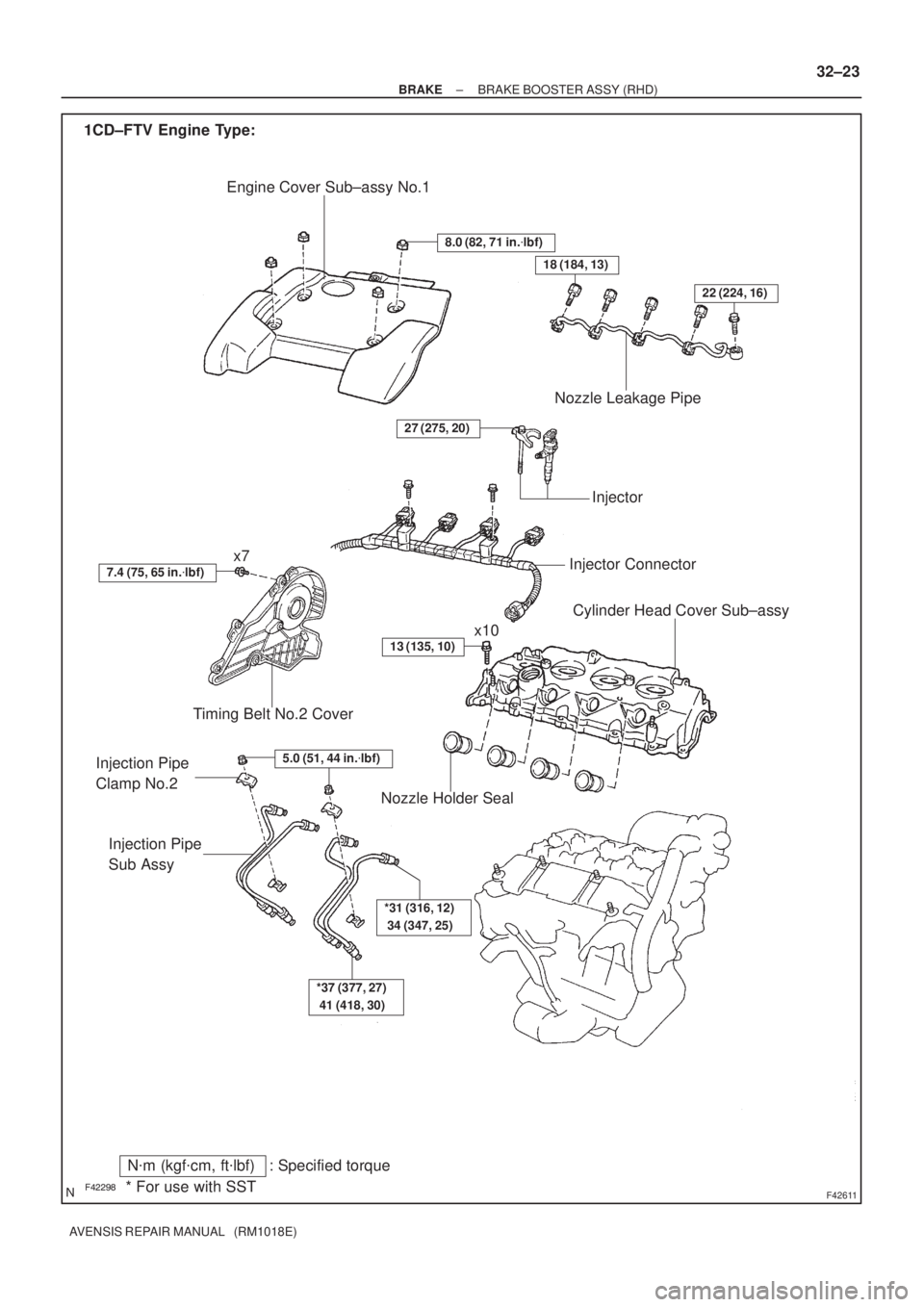
Engine Cover Sub±assy No.1
Timing Belt No.2 Cover
x7
Injector Connector
Cylinder Head Cover Sub±assy
Injection Pipe
Sub Assy
Nozzle Holder Seal
Nozzle Leakage Pipe
Injector
x10 1CD±FTV Engine Type:
8.0 (82, 71 in.�lbf)
N�m (kgf�cm, ft�lbf) : Specified torque
* For use with SST
13 (135, 10)
5.0 (51, 44 in.�lbf)
*37 (377, 27)
41 (418, 30)
*31 (316, 12)
34 (347, 25)
7.4 (75, 65 in.�lbf)
Injection Pipe
Clamp No.2
27 (275, 20)
18 (184, 13)
22 (224, 16)
± BRAKEBRAKE BOOSTER ASSY (RHD)
32±23
AVENSIS REPAIR MANUAL (RM1018E)
Page 45 of 1690
F45161
Brake Master
Cylinder Sub±assy
Clutch Master Cylinder AssyM/T Transaxle: Vacuum Tank Diesel Engine Type:
Brake Fulid Level
Switch Connector Accelerator Control
Cable Support
20 (204, 15)
19 (194, 14)
Clutch Reservoir
Hose M/T Transaxle: Brake Booster Assy� Brake Booster Gasket
Brake Master Cylinder
ClevisClip Clevis Pin
13 (130, 9)
15 (155, 11) *1
29 (296, 21) *2
15 (155, 11)
N�m (kgf�cm, ft�lbf)
: Specified torque
5.4 (55, 48 in.�lbf)
8.3 (85, 73 in.�lbf)
Wave Washer
Check Valve Grommet
15 (155, 11)
5.4 (55, 48 in.�lbf)
*1 w/ ABS:
*2 w/ VSC:
32±24
± BRAKEBRAKE BOOSTER ASSY (RHD)
AVENSIS REPAIR MANUAL (RM1018E)
Page 46 of 1690

32±25
AVENSIS REPAIR MANUAL (RM1018E)
REPLACEMENT
NOTICE:
Do not adjust the brake booster push rod.
1. DRAIN BRAKE FLUID
NOTICE:
Wash the b")
320W4±01
G24211
F42291
±
BRAKE BRAKE BOOSTER ASSY (RHD)
32±25
AVENSIS REPAIR MANUAL (RM1018E)
REPLACEMENT
NOTICE:
Do not adjust the brake booster push rod.
1. DRAIN BRAKE FLUID
NOTICE:
Wash the brake fluid off immediately if it adheres to any painted surface\
.
2.REMOVE BRAKE MASTER CYLINDER SUB±ASSY (See page 32±13)
(a) w/o VSC:
SST 09023±00100
(b) w/ VSC: SST 09023±38400
3.REMOVE CLUTCH MASTER CYLINDER ASSY (M/T TRANSAXLE) (See page 42±13) SST 09023±00100
4. REMOVE ENGINE ASSEMBLY WITH TRANSAXLE (1AZ±FSE ENGINE TYPE) (See page 14±204)
5. REMOVE ENGINE COVER NO.1
6.REMOVE IGNITION COIL ASSY (GASOLINE ENGINE TYPE) (See page 14±81)
7.REMOVE CYLINDER HEAD COVER SUB±ASSY (GASOLINE ENGINE TYPE) (See page 14±81)
8.REMOVE TIMING BELT NO.2 COVER (DIESEL ENGINE TYPE) (See page 14±307)
9.REMOVE CYLINDER HEAD COVER SUB±ASSY (DIESEL ENGINE TYPE) (See page 14±318)
10.REMOVE INJECTOR ASSY (DIESEL ENGINE TYPE) (See page 14±318)
11. REMOVE FRONT WHEEL RH
12. REMOVE BRAKE TUBE
(a) w/o VSC:Using SST, disconnect the 6 brake tubes from the brake
actuator.
SST 09023±00100
(b) w/ VSC: Using SST, disconnect the 6 brake tubes from the brake
actuator.
SST 09023±00100, 09023±38400
Page 48 of 1690
F45361
F45362
F45367
F45363Vacuum tank
C81275
± BRAKEBRAKE BOOSTER ASSY (RHD)
32±27
AVENSIS REPAIR MANUAL (RM1018E)
(f) Using SST, disconnect the 3 brake tubes from the ways.
SST 09023±00100
(g) Disconnect the brake tube from the clamp and remove
the brake tubes.
(h) Disconnect the 3 brake tubes from the clamp and remove
the brake tubes.
13. REMOVE BRAKE BOOSTER ASSY
(a) Gasoline engine type:
Remove the 2 bolts and separate the vacuum pipe from
the body.
(b) Diesel engine type:
Remove the 2 bolts and remove the vacuum tank from the
body.
(c) Disconnect the vacuum hose from the brake booster
assy.
(d) Remove the engine under cover.
(e) Remove the 2 nuts from the engine mounting bracket RH.
(f) Remove the bolt from the rear engine mounting bracket.
(g) Remove the bolt and nut from the front engine mounting
bracket.
Page 49 of 1690
F40021
Wooden Block
C82119
C80809
C80805
32±28
± BRAKEBRAKE BOOSTER ASSY (RHD)
AVENSIS REPAIR MANUAL (RM1018E)
(h) Hold the engine with a jack, putting a wooden block be-
tween them.
(i) Remove the 3 bolts and separate the engine mounting
bracket RH from the body.
(j) Gradually tilt the engine by lowering the jack to remove
the brake booster assy.
(k) Remove the 4 nuts and clevis.
(l) Pull out the brake booster assy.
14. REMOVE BRAKE BOOSTER GASKET
(a) Pull out the brake booster gasket.
15. REMOVE CHECK VALVE
(a) Remove the check valve from the brake booster assy.
16. INSTALL CHECK VALVE
(a) Install the check valve and grommet to the brake booster assy.
17. INSTALL BRAKE BOOSTER GASKET
(a) Install a new brake booster gasket to the brake booster assy.
Page 50 of 1690
C80805
C82119
C81275
C81274
F45367
± BRAKEBRAKE BOOSTER ASSY (RHD)
32±29
AVENSIS REPAIR MANUAL (RM1018E)
18. INSTALL BRAKE BOOSTER ASSY
(a) Install the clevis to the booster push rod.
(b) Install the brake booster assy with the 4 nuts.
Torque: 13 N�m (130 kgf�cm, 9 ft�lbf)
(c) Connect the vacuum hose to the check valve.
(d) Install the engine mounting bracket RH to the body with
the 3 bolts.
Torque: 52 N�m (530 kgf�cm, 39 ft�lbf)
(e) Install the bolt to the rear engine mounting bracket.
Torque: 87 N�m (887 kgf�cm, 64 ft�lbf)
(f) Install the bolt and nut to the front engine mounting brack-
et.
Torque: 52 N�m (530 kgf�cm, 39 ft�lbf)
(g) Install the 2 nuts to the engine mounting bracket RH.
Torque: 52 N�m (530 kgf�cm, 39 ft�lbf)
(h) Install the engine under cover.
(i) Connect the vacuum hose to the brake booster assy.
(j) Gasoline engine type:
Install the vacuum pipe with 2 bolts to the body.
Torque: 5.4 N�m (55 kgf�cm, 48 in.�lbf)
Page 51 of 1690
F45363Vacuum tank
F45362
F45361
C80802
32±30
± BRAKEBRAKE BOOSTER ASSY (RHD)
AVENSIS REPAIR MANUAL (RM1018E)
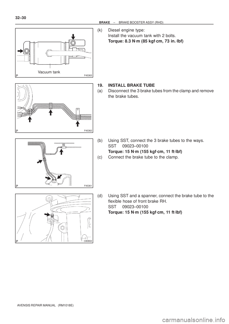
(k) Diesel engine type:
Install the vacuum tank with 2 bolts.
Torque: 8.3 N�m (85 kgf�cm, 73 in.�lbf)
19. INSTALL BRAKE TUBE
(a) Disconnect the 3 brake tubes from the clamp and remove
the brake tubes.
(b) Using SST, connect the 3 brake tubes to the ways.
SST 09023±00100
Torque: 15 N�m (155 kgf�cm, 11 ft�lbf)
(c) Connect the brake tube to the clamp.
(d) Using SST and a spanner, connect the brake tube to the
flexible hose of front brake RH.
SST 09023±00100
Torque: 15 N�m (155 kgf�cm, 11 ft�lbf)
Page 52 of 1690

F45057
w/o VSC:
w/ VSC:
To Master
Cylinder Rear
To
Master
Cylinder
Front
To Rear Wheel
RH
To Front Wheel LH
To Front Wheel RH
To Rear Wheel
LH
A
To
Master
Cylinder
FrontTo Master
Cylinder
Rear
To Rear
Wheel RH
To Front Wheel LHTo Front Wheel RH
To Rear
Wheel LH
AA
AA
BB
C80806
±
BRAKE BRAKE BOOSTER ASSY (RHD)
32±31
AVENSIS REPAIR MANUAL (RM1018E)
(e) w/o VSC:
Using SST, connect the 6 brake tubes to the brake actua-
tor, as shown in the illustration.
SST 09023±00100
Torque: 15 N �m (155 kgf �cm, 11 ft �lbf)
(f) w/ VSC: Using SST, connect the 6 brake tubes to the brake actua-
tor as shown in the illustration.
SST 09023±00100, 09023±38400
Torque:
A: 15 N �m (155 kgf �cm, 11 ft �lbf)
B: 29 N �m (296 kgf �cm, 21 ft �lbf)
(g) Install the brake tube clamps with the 2 bolts. Torque: 5.4 N �m (55 kgf �cm, 48 in. �lbf)
20. INSTALL FRONT WHEEL RH
21.INSTALL CYLINDER HEAD COVER SUB±ASSY (GASOLINE ENGINE TYPE) (See page 14±81)
22.INSTALL IGNITION COIL ASSY (GASOLINE ENGINE TYPE) (See page 14±81)
23.INSTALL INJECTOR ASSY (DIESEL ENGINE TYPE) (See page 14±318)
24.INSTALL CYLINDER HEAD COVER SUB±ASSY (DIESEL ENGINE TYPE) (See page 14±318)
25.INSTALL TIMING BELT NO.2 COVER (DIESEL ENGINE TYPE) (See page 14±307)

19 (")

32±27
AVENSIS REPAIR MANUAL (RM1018E)
(f) Using SST, disconnect the 3 brake tubes from the ways.
SST 09023±00100
(g)")

AVENSIS REPAIR MANUAL (RM1018E)
(h) Hold the engine with a jack, putting a wooden block be-
tween them.
(i) Remove th")

32±29
AVENSIS REPAIR MANUAL (RM1018E)
18. INSTALL BRAKE BOOSTER ASSY
(a) Install the clevis to the booster push rod.
(b) Install")