Page 600 of 1767
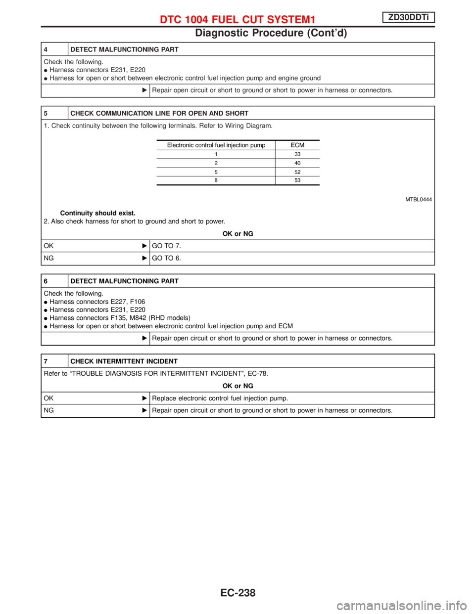
4 DETECT MALFUNCTIONING PART
Check the following.
IHarness connectors E231, E220
IHarness for open or short between electronic control fuel injection pump and engine ground
ERepair open circuit or short to ground or short to power in harness or connectors.
5 CHECK COMMUNICATION LINE FOR OPEN AND SHORT
1. Check continuity between the following terminals. Refer to Wiring Diagram.
MTBL0444
Continuity should exist.
2. Also check harness for short to ground and short to power.
OK or NG
OKEGO TO 7.
NGEGO TO 6.
6 DETECT MALFUNCTIONING PART
Check the following.
IHarness connectors E227, F106
IHarness connectors E231, E220
IHarness connectors F135, M842 (RHD models)
IHarness for open or short between electronic control fuel injection pump and ECM
ERepair open circuit or short to ground or short to power in harness or connectors.
7 CHECK INTERMITTENT INCIDENT
Refer to ªTROUBLE DIAGNOSIS FOR INTERMITTENT INCIDENTº, EC-78.
OK or NG
OKEReplace electronic control fuel injection pump.
NGERepair open circuit or short to ground or short to power in harness or connectors.
DTC 1004 FUEL CUT SYSTEM1ZD30DDTi
Diagnostic Procedure (Cont'd)
EC-238
Page 668 of 1767
Fuel Injection System
SYSTEM DESCRIPTION
Three types of fuel injection control are provided to accommodate engine operating conditions; normal control,
idle control and start control. The ECM determines the appropriate fuel injection control. Under each control,
the amount of fuel injected is compensated to improve engine performance. The ECM performs duty cycle
control on the electric governor (built into the fuel injection pump) according to sensor signals to compensate
the amount of fuel injected to the preset value.
START CONTROL
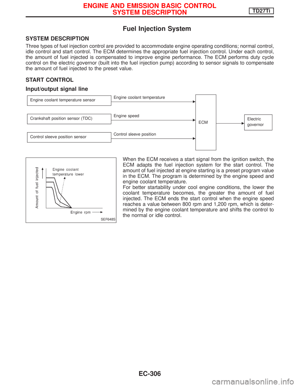
Input/output signal line
Engine coolant temperature sensorEEngine coolant temperature
ECM
EElectric
governorCrankshaft position sensor (TDC)EEngine speed
Control sleeve position sensor
EControl sleeve position
When the ECM receives a start signal from the ignition switch, the
ECM adapts the fuel injection system for the start control. The
amount of fuel injected at engine starting is a preset program value
in the ECM. The program is determined by the engine speed and
engine coolant temperature.
For better startability under cool engine conditions, the lower the
coolant temperature becomes, the greater the amount of fuel
injected. The ECM ends the start control when the engine speed
reaches a value between 800 rpm and 1,200 rpm, which is deter-
mined by the engine coolant temperature and shifts the control to
the normal or idle control.
SEF648S
ENGINE AND EMISSION BASIC CONTROL
SYSTEM DESCRIPTIONTD27Ti
EC-306
Page 670 of 1767
FUEL TEMPERATURE COMPENSATION
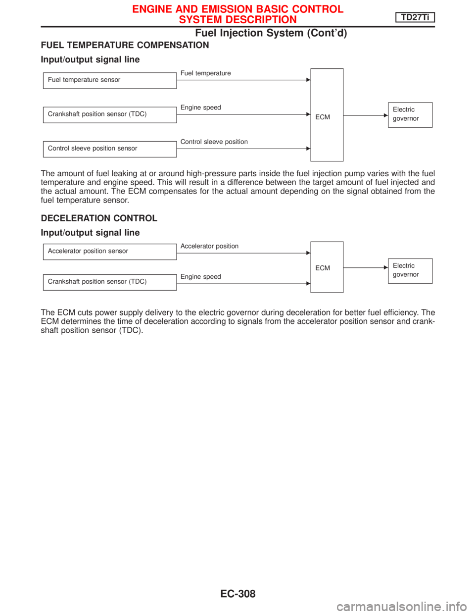
Input/output signal line
Fuel temperature sensorEFuel temperature
ECM
EElectric
governorCrankshaft position sensor (TDC)EEngine speed
Control sleeve position sensor
EControl sleeve position
The amount of fuel leaking at or around high-pressure parts inside the fuel injection pump varies with the fuel
temperature and engine speed. This will result in a difference between the target amount of fuel injected and
the actual amount. The ECM compensates for the actual amount depending on the signal obtained from the
fuel temperature sensor.
DECELERATION CONTROL
Input/output signal line
Accelerator position sensorEAccelerator position
ECM
EElectric
governor
Crankshaft position sensor (TDC)EEngine speed
The ECM cuts power supply delivery to the electric governor during deceleration for better fuel efficiency. The
ECM determines the time of deceleration according to signals from the accelerator position sensor and crank-
shaft position sensor (TDC).
ENGINE AND EMISSION BASIC CONTROL
SYSTEM DESCRIPTIONTD27Ti
Fuel Injection System (Cont'd)
EC-308
Page 678 of 1767
Test and Adjustment
WARNING:
When using nozzle tester, be careful not to allow diesel fuel
sprayed from nozzle to contact your hands or body, and make
sure your eyes are properly protected with goggles.
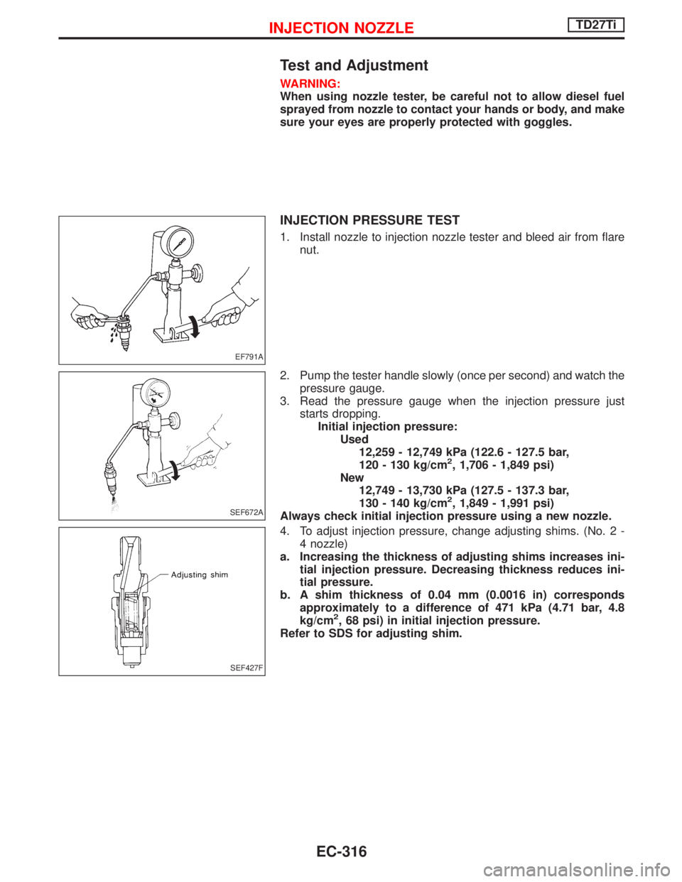
INJECTION PRESSURE TEST
1. Install nozzle to injection nozzle tester and bleed air from flare
nut.
2. Pump the tester handle slowly (once per second) and watch the
pressure gauge.
3. Read the pressure gauge when the injection pressure just
starts dropping.
Initial injection pressure:
Used
12,259 - 12,749 kPa (122.6 - 127.5 bar,
120 - 130 kg/cm
2, 1,706 - 1,849 psi)
New
12,749 - 13,730 kPa (127.5 - 137.3 bar,
130 - 140 kg/cm
2, 1,849 - 1,991 psi)
Always check initial injection pressure using a new nozzle.
4. To adjust injection pressure, change adjusting shims. (No. 2 -
4 nozzle)
a. Increasing the thickness of adjusting shims increases ini-
tial injection pressure. Decreasing thickness reduces ini-
tial pressure.
b. A shim thickness of 0.04 mm (0.0016 in) corresponds
approximately to a difference of 471 kPa (4.71 bar, 4.8
kg/cm
2, 68 psi) in initial injection pressure.
Refer to SDS for adjusting shim.
EF791A
SEF672A
SEF427F
INJECTION NOZZLETD27Ti
EC-316
Page 680 of 1767
q1Electric fuel injection pump
q
2Key
q
3Bracketq
4Injection pump drive gear
q
5Dust cover
q
6Bracketq
7Gasket
q
8Gasket
Removal
1. Remove battery.
Disconnect electronic injection pump harness connectors.
2. Set No. 1 piston at TDC on its compression stroke.
3. Remove fuel hoses (supply, return and spill) and injection
tubes.
NEF460
EEF181
ELECTRONIC FUEL INJECTION PUMPTD27Ti
EC-318
Page 681 of 1767
4. Remove dust cover and injection pump gear.
Refer to EM section.
5. Remove fixing nuts and bolts. Then remove injection pump.
Installation
Install injection pump assembly in the reverse order of removal,
observing the following:
1. Confirm that No. 1 cylinder is set at TDC on its compression
stroke.
2. Install injection pump (Refer to EM section).
(1) Temporarily set injection pump so that the flange of the pump
is aligned with aligning mark on front cover.
(2) Install injection pump gear.
:59-69N×m (6 - 7 kg-m, 43 - 51 ft-lb)
Make sure that the key does not fall into the front cover.
Make sure that ªZº marks are aligned.
(3) Apply liquid gasket to mating surface of injection pump gear
cover and install it.
3. Adjust injection timing.
Refer to ªBasic Inspectionº, EC-338.
4. Install all parts removed.
SEM653B
EEF160
EEF181
SEF337F
ELECTRONIC FUEL INJECTION PUMPTD27Ti
Removal (Cont'd)
EC-319
Page 682 of 1767
Disassembly and Assembly
CAUTION:
IDo not disassemble the parts not shown in the illustration
above.
IBefore installing injection timing control valve, smear a
coat of diesel fuel to O-ring and its mating area. Insert
injection timing control valve straight into bore in fuel
pump body. After positioning the injection timing control
valve correctly, visually check that the fuel does not leak.
IAfter re-assembling the parts, erase Diagnostic Trouble
Code (DTC), and perform DTC CONFIRMATION PROCE-
DURE (or OVERALL FUNCTION CHECK).
YEC236A
ELECTRONIC FUEL INJECTION PUMPTD27Ti
EC-320
Page 690 of 1767
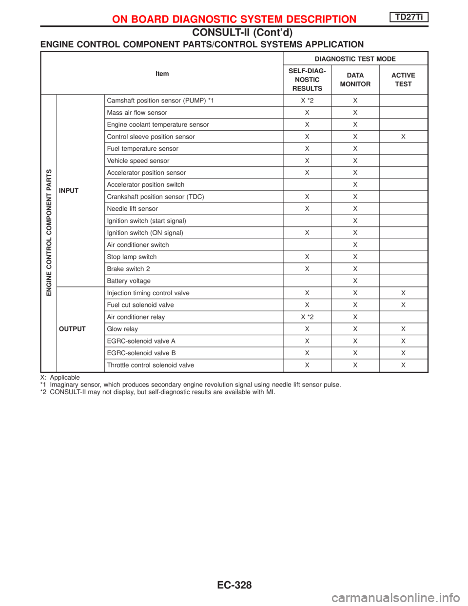
ENGINE CONTROL COMPONENT PARTS/CONTROL SYSTEMS APPLICATION
ItemDIAGNOSTIC TEST MODE
SELF-DIAG-
NOSTIC
RESULTSD ATA
MONITORACTIVE
TEST
ENGINE CONTROL COMPONENT PARTS
INPUTCamshaft position sensor (PUMP) *1 X *2 X
Mass air flow sensor X X
Engine coolant temperature sensor X X
Control sleeve position sensor X X X
Fuel temperature sensor X X
Vehicle speed sensor X X
Accelerator position sensor X X
Accelerator position switch X
Crankshaft position sensor (TDC) X X
Needle lift sensor X X
Ignition switch (start signal) X
Ignition switch (ON signal) X X
Air conditioner switch X
Stop lamp switch X X
Brake switch 2 X X
Battery voltage X
OUTPUTInjection timing control valve X X X
Fuel cut solenoid valve X X X
Air conditioner relay X *2 X
Glow relay X X X
EGRC-solenoid valve A X X X
EGRC-solenoid valve B X X X
Throttle control solenoid valve X X X
X: Applicable
*1 Imaginary sensor, which produces secondary engine revolution signal using needle lift sensor pulse.
*2 CONSULT-II may not display, but self-diagnostic results are available with MI.
ON BOARD DIAGNOSTIC SYSTEM DESCRIPTIONTD27Ti
CONSULT-II (Cont'd)
EC-328