2002 NISSAN TERRANO fuel pump
[x] Cancel search: fuel pumpPage 737 of 1767
Component Inspection
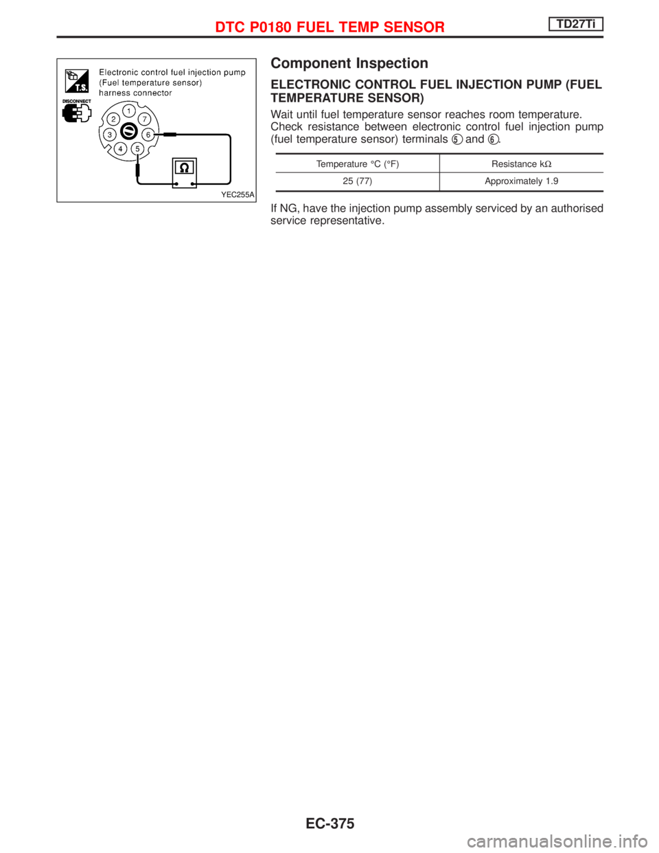
ELECTRONIC CONTROL FUEL INJECTION PUMP (FUEL
TEMPERATURE SENSOR)
Wait until fuel temperature sensor reaches room temperature.
Check resistance between electronic control fuel injection pump
(fuel temperature sensor) terminalsq
5andq6.
Temperature ÉC (ÉF) Resistance kW
25 (77) Approximately 1.9
If NG, have the injection pump assembly serviced by an authorised
service representative.
YEC255A
DTC P0180 FUEL TEMP SENSORTD27Ti
EC-375
Page 742 of 1767
Component Description
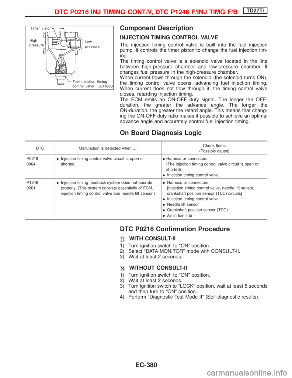
INJECTION TIMING CONTROL VALVE
The injection timing control valve is built into the fuel injection
pump. It controls the timer piston to change the fuel injection tim-
ing.
The timing control valve is a solenoid valve located in the line
between high-pressure chamber and low-pressure chamber. It
changes fuel pressure in the high-pressure chamber.
When current flows through the solenoid (the solenoid turns ON),
the timing control valve opens, advancing fuel injection timing.
When current does not flow through it, the timing control valve
closes, retarding injection timing.
The ECM emits an ON-OFF duty signal. The longer the OFF-
duration, the greater the advance angle. The longer the
ON-duration, the greater the retard angle. This means that chang-
ing the ON-OFF duty ratio makes it possible to achieve an optimal
advance angle and accurately control fuel injection timing.
On Board Diagnosis Logic
DTC Malfunction is detected when ....Check Items
(Possible cause)
P0216
0904IInjection timing control valve circuit is open or
shorted.IHarness or connectors
(The injection timing control valve circuit is open or
shorted)
IInjection timing control valve
P1246
0201IInjection timing feedback system does not operate
properly. (This system consists essentially of ECM,
injection timing control valve and needle lift sensor.)IHarness or connectors
[Injection timing control valve, needle lift sensor,
crankshaft position sensor (TDC) circuits]
IInjection timing control valve
INeedle lift sensor
ICrankshaft position sensor (TDC)
IAir in fuel line
DTC P0216 Confirmation Procedure
WITH CONSULT-II
1) Turn ignition switch to ªONº position.
2) Select ªDATA MONITORº mode with CONSULT-II.
3) Wait at least 2 seconds.
WITHOUT CONSULT-II
1) Turn ignition switch to ªONº position.
2) Wait at least 2 seconds.
3) Turn ignition switch to ªLOCKº position, wait at least 5 seconds
and then turn to ªONº position.
4) Perform ªDiagnostic Test Mode IIº (Self-diagnostic results).
SEF638S
DTC P0216 INJ TIMING CONT/V, DTC P1246 F/INJ TIMG F/BTD27Ti
EC-380
Page 745 of 1767

Diagnostic Procedure
INSPECTION START
CHECK FOR AIR IN FUEL FILTER.
1. Move priming pump up and down to
purge air from fuel filter.
2. Perform ªDIAGNOSTIC TROUBLE
CODE CONFIRMATION PROCE-
DUREº.
CHECK POWER SUPPLY.
1. Turn ignition switch to ªLOCKº position.
2. Disconnect TVC and shut-off (injection
timing control valve) harness connec-
tor.
3. Turn ignition switch to ªONº position.
4. Check voltage between TVC and shut-
off (injection timing control valve) con-
nector terminalq
9and engine ground
with CONSULT-II or tester.
Voltage: Battery voltage
OK
ENG
Check the following:
IHarness connector
M787,F66
I20A fuse
IECM relay
IHarness for open or
short-circuit between
TVC and shut-off (injec-
tion timing control valve)
harness connector and
fuse box.
If NG, replace 20A fuse or
ECM relay, harness or con-
nectors.
CHECK OUTPUT SIGNAL CIRCUIT.
1. Turn ignition switch to ªLOCKº position.
2. Disconnect ECM harness connector.
3. Check harness continuity between TVC
and shut-off (injection timing control
valve) connector terminalq
8and ECM
terminals
202. Refer to wiring dia-
gram.
Continuity should exist.
If OK, check harness for short-circuit.
OK
ENG
Check the following:
IHarness for open or
short-circuit between
TVC and shut-off (injec-
tion timing control valve)
and ECM
If NG, repair harness or
connectors.
CHECK GROUND CIRCUIT.
1. Disconnect ECM harness connector.
2. Check harness continuity between
ECM connector terminal
349and TVC
and shut-off (injection timing control
valve) connector terminalq
10. Refer to
wiring diagram.
Continuity should exist.
If OK, check harness of short-circuit.
OK
ENG
Repair harness or connec-
tors
qA
YEC256A
NEF463
MEC947D
H
H
H
H
H
DTC P0216 INJ TIMING CONT/V, DTC P1246 F/INJ TIMG F/BTD27Ti
EC-383
Page 771 of 1767
Component Description
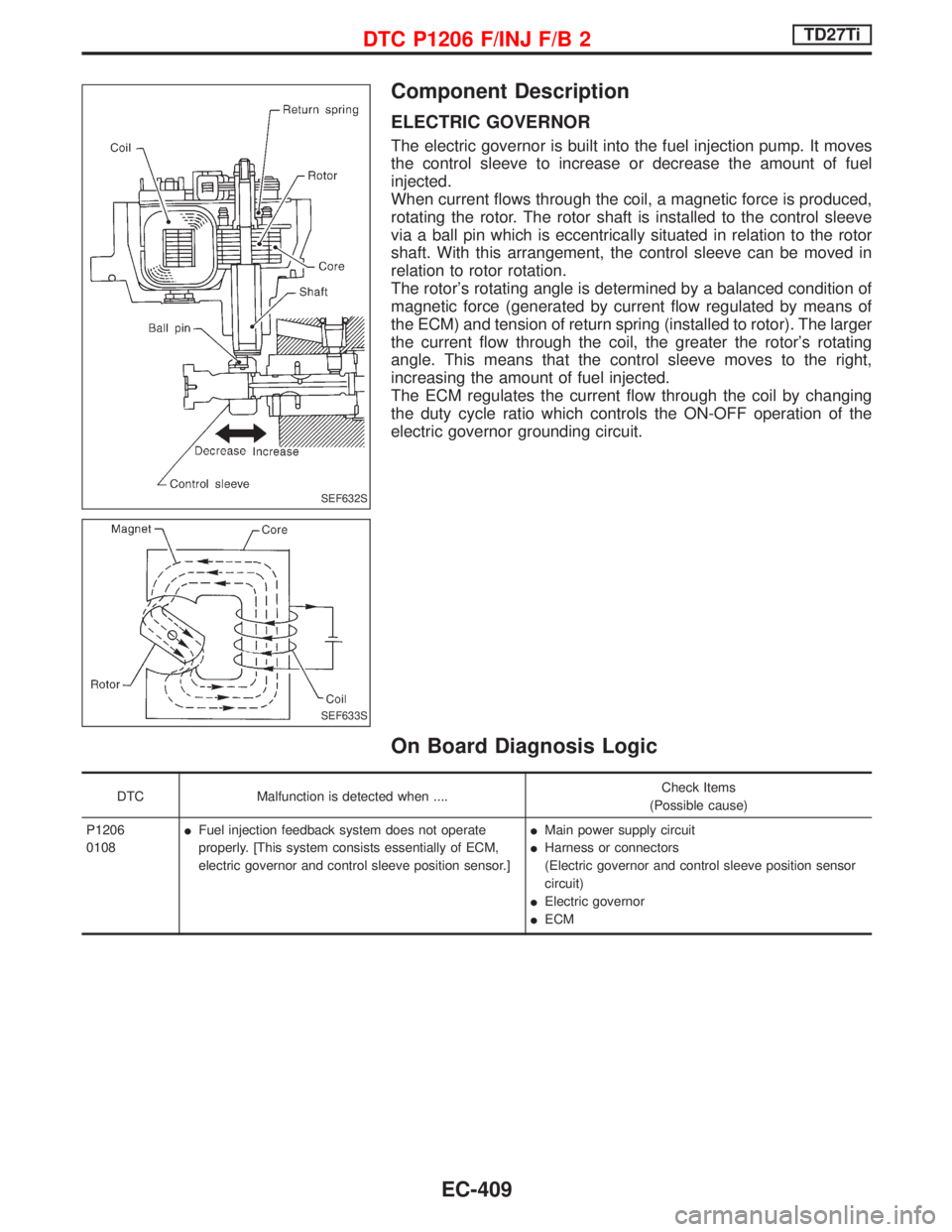
ELECTRIC GOVERNOR
The electric governor is built into the fuel injection pump. It moves
the control sleeve to increase or decrease the amount of fuel
injected.
When current flows through the coil, a magnetic force is produced,
rotating the rotor. The rotor shaft is installed to the control sleeve
via a ball pin which is eccentrically situated in relation to the rotor
shaft. With this arrangement, the control sleeve can be moved in
relation to rotor rotation.
The rotor's rotating angle is determined by a balanced condition of
magnetic force (generated by current flow regulated by means of
the ECM) and tension of return spring (installed to rotor). The larger
the current flow through the coil, the greater the rotor's rotating
angle. This means that the control sleeve moves to the right,
increasing the amount of fuel injected.
The ECM regulates the current flow through the coil by changing
the duty cycle ratio which controls the ON-OFF operation of the
electric governor grounding circuit.
On Board Diagnosis Logic
DTC Malfunction is detected when ....Check Items
(Possible cause)
P1206
0108IFuel injection feedback system does not operate
properly. [This system consists essentially of ECM,
electric governor and control sleeve position sensor.]IMain power supply circuit
IHarness or connectors
(Electric governor and control sleeve position sensor
circuit)
IElectric governor
IECM
SEF632S
SEF633S
DTC P1206 F/INJ F/B 2TD27Ti
EC-409
Page 778 of 1767
Diagnostic Procedure
INSPECTION START
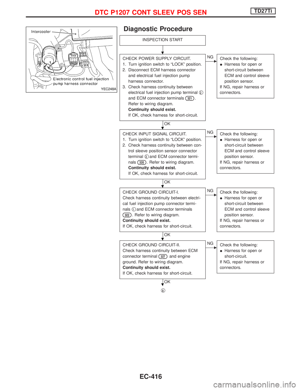
CHECK POWER SUPPLY CIRCUIT.
1. Turn ignition switch to ªLOCKº position.
2. Disconnect ECM harness connector
and electrical fuel injection pump
harness connector.
3. Check harness continuity between
electrical fuel injection pump terminalq
2
and ECM connector terminals321.
Refer to wiring diagram.
Continuity should exist.
If OK, check harness for short-circuit.
OK
ENG
Check the following:
IHarness for open or
short-circuit between
ECM and control sleeve
position sensor.
If NG, repair harness or
connectors.
CHECK INPUT SIGNAL CIRCUIT.
1. Turn ignition switch to ªLOCKº position.
2. Check harness continuity between con-
trol sleeve position sensor connector
terminalq
3and ECM connector termi-
nals
320. Refer to wiring diagram.
Continuity should exist.
If OK, check harness for short-circuit.
OK
ENG
Check the following:
IHarness for open or
short-circuit between
ECM and control sleeve
position sensor.
If NG, repair harness or
connectors.
CHECK GROUND CIRCUIT-I.
Check harness continuity between electri-
cal fuel injection pump connector termi-
nalsq
1and ECM connector terminals
322. Refer to wiring diagram.
Continuity should exist.
If OK, check harness for short-circuit.
OK
ENG
Check the following:
IHarness for open or
short-circuit between
ECM and control sleeve
position sensor.
If NG, repair harness or
connectors.
CHECK GROUND CIRCUIT-II.
Check harness continuity between ECM
connector terminal
327and engine
ground. Refer to wiring diagram.
Continuity should exist.
If OK, check harness for short-circuit.
OK
ENG
Check the following:
IHarness for open or
short-circuit.
If NG, repair harness or
connectors.
qA
YEC248A
H
H
H
H
H
DTC P1207 CONT SLEEV POS SENTD27Ti
EC-416
Page 791 of 1767
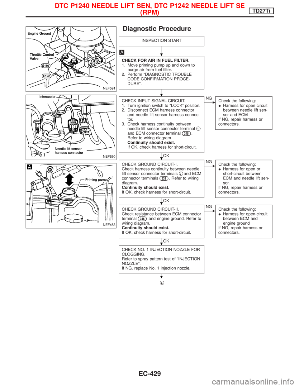
Diagnostic Procedure
INSPECTION START
CHECK FOR AIR IN FUEL FILTER.
1. Move priming pump up and down to
purge air from fuel filter.
2. Perform ªDIAGNOSTIC TROUBLE
CODE CONFIRMATION PROCE-
DUREº.
CHECK INPUT SIGNAL CIRCUIT.
1. Turn ignition switch to ªLOCKº position.
2. Disconnect ECM harness connector
and needle lift sensor harness connec-
tor.
3. Check harness continuity between
needle lift sensor connector terminalq
1and ECM connector terminal345.
Refer to wiring diagram.
Continuity should exist.
If OK, check harness for short-circuit.
OK
ENG
Check the following:
IHarness for open circuit
between needle lift sen-
sor and ECM
If NG, repair harness or
connectors.
CHECK GROUND CIRCUIT-I.
Check harness continuity between needle
lift sensor connector terminalsq
2and ECM
connector terminals333. Refer to wiring
diagram.
Continuity should exist.
If OK, check harness for short-circuit.
OK
ENG
Check the following:
IHarness for open or
short-circuit between
ECM and needle lift sen-
sor.
If NG, repair harness or
connectors.
CHECK GROUND CIRCUIT-II.
Check resistance between ECM connector
terminal
346and engine ground. Refer to
wiring diagram.
Continuity should exist.
If OK, check harness for short-circuit.
OK
ENG
Check the following:
IHarness for open-circuit
between ECM and
engine ground
If NG, repair harness or
connectors.
CHECK NO. 1 INJECTION NOZZLE FOR
CLOGGING.
Refer to spray pattern test of ªINJECTION
NOZZLEº.
If NG, replace No. 1 injection nozzle.
qA
NEF591
NEF690
NEF463
H
H
H
H
H
H
DTC P1240 NEEDLE LIFT SEN, DTC P1242 NEEDLE LIFT SE
(RPM)TD27Ti
EC-429
Page 815 of 1767
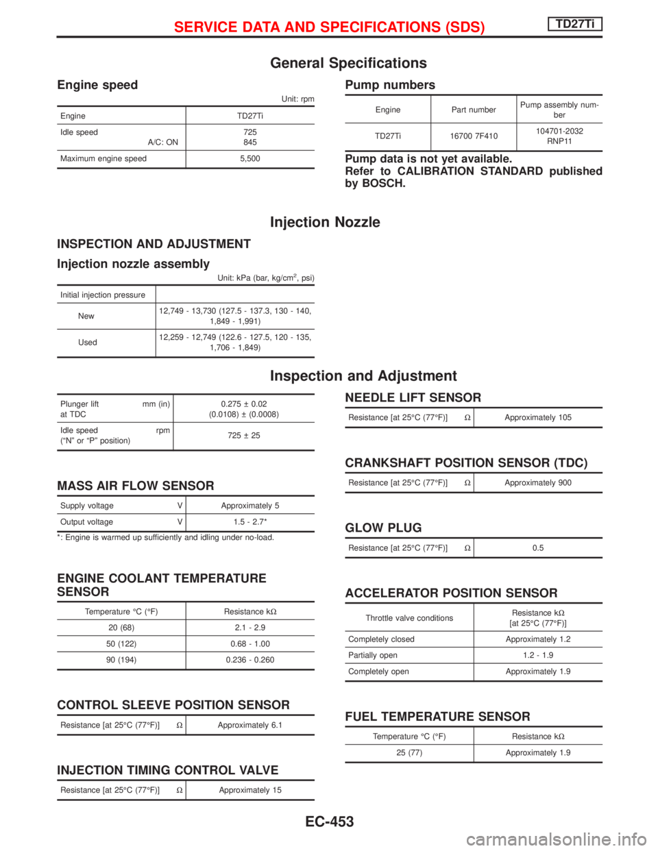
General Specifications
Engine speed
Unit: rpm
Engine TD27Ti
Idle speed
A/C: ON725
845
Maximum engine speed 5,500
Pump numbers
Engine Part numberPump assembly num-
ber
TD27Ti 16700 7F410104701-2032
RNP11
Pump data is not yet available.
Refer to CALIBRATION STANDARD published
by BOSCH.
Injection Nozzle
INSPECTION AND ADJUSTMENT
Injection nozzle assembly
Unit: kPa (bar, kg/cm2, psi)
Initial injection pressure
New12,749 - 13,730 (127.5 - 137.3, 130 - 140,
1,849 - 1,991)
Used12,259 - 12,749 (122.6 - 127.5, 120 - 135,
1,706 - 1,849)
Inspection and Adjustment
Plunger lift mm (in)
at TDC0.275 0.02
(0.0108) (0.0008)
Idle speed rpm
(ªNº or ªPº position)725 25
MASS AIR FLOW SENSOR
Supply voltage V Approximately 5
Output voltage V 1.5 - 2.7*
*: Engine is warmed up sufficiently and idling under no-load.
ENGINE COOLANT TEMPERATURE
SENSOR
Temperature ÉC (ÉF) Resistance kW
20 (68) 2.1 - 2.9
50 (122) 0.68 - 1.00
90 (194) 0.236 - 0.260
CONTROL SLEEVE POSITION SENSOR
Resistance [at 25ÉC (77ÉF)]WApproximately 6.1
INJECTION TIMING CONTROL VALVE
Resistance [at 25ÉC (77ÉF)]WApproximately 15
NEEDLE LIFT SENSOR
Resistance [at 25ÉC (77ÉF)]WApproximately 105
CRANKSHAFT POSITION SENSOR (TDC)
Resistance [at 25ÉC (77ÉF)]WApproximately 900
GLOW PLUG
Resistance [at 25ÉC (77ÉF)]W0.5
ACCELERATOR POSITION SENSOR
Throttle valve conditionsResistance kW
[at 25ÉC (77ÉF)]
Completely closed Approximately 1.2
Partially open 1.2 - 1.9
Completely open Approximately 1.9
FUEL TEMPERATURE SENSOR
Temperature ÉC (ÉF) Resistance kW
25 (77) Approximately 1.9
SERVICE DATA AND SPECIFICATIONS (SDS)TD27Ti
EC-453
Page 837 of 1767
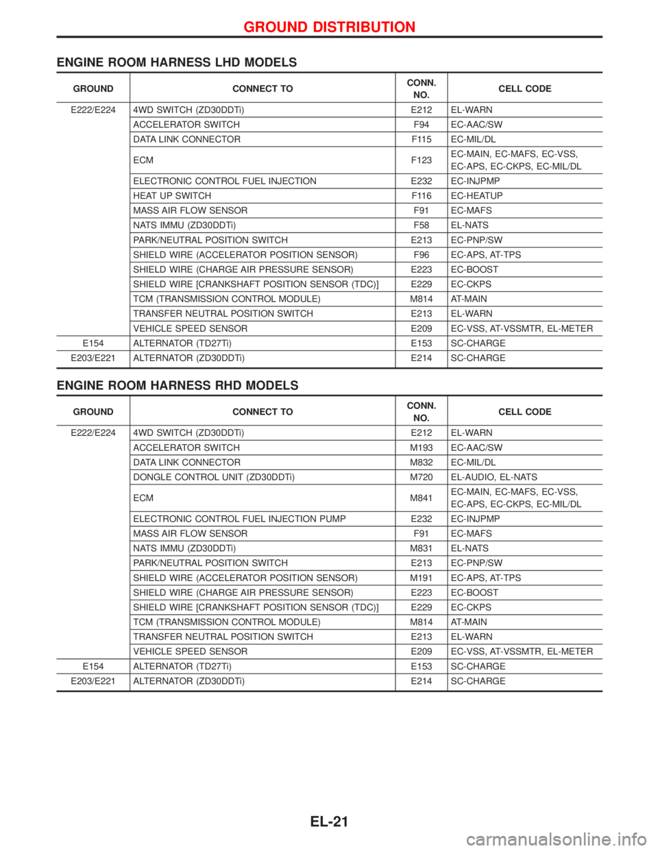
ENGINE ROOM HARNESS LHD MODELS
GROUND CONNECT TOCONN.
NO.CELL CODE
E222/E224 4WD SWITCH (ZD30DDTi) E212 EL-WARN
ACCELERATOR SWITCH F94 EC-AAC/SW
DATA LINK CONNECTOR F115 EC-MIL/DL
ECM F123EC-MAIN, EC-MAFS, EC-VSS,
EC-APS, EC-CKPS, EC-MIL/DL
ELECTRONIC CONTROL FUEL INJECTION E232 EC-INJPMP
HEAT UP SWITCH F116 EC-HEATUP
MASS AIR FLOW SENSOR F91 EC-MAFS
NATS IMMU (ZD30DDTi) F58 EL-NATS
PARK/NEUTRAL POSITION SWITCH E213 EC-PNP/SW
SHIELD WIRE (ACCELERATOR POSITION SENSOR) F96 EC-APS, AT-TPS
SHIELD WIRE (CHARGE AIR PRESSURE SENSOR) E223 EC-BOOST
SHIELD WIRE [CRANKSHAFT POSITION SENSOR (TDC)] E229 EC-CKPS
TCM (TRANSMISSION CONTROL MODULE) M814 AT-MAIN
TRANSFER NEUTRAL POSITION SWITCH E213 EL-WARN
VEHICLE SPEED SENSOR E209 EC-VSS, AT-VSSMTR, EL-METER
E154 ALTERNATOR (TD27Ti) E153 SC-CHARGE
E203/E221 ALTERNATOR (ZD30DDTi) E214 SC-CHARGE
ENGINE ROOM HARNESS RHD MODELS
GROUND CONNECT TOCONN.
NO.CELL CODE
E222/E224 4WD SWITCH (ZD30DDTi) E212 EL-WARN
ACCELERATOR SWITCH M193 EC-AAC/SW
DATA LINK CONNECTOR M832 EC-MIL/DL
DONGLE CONTROL UNIT (ZD30DDTi) M720 EL-AUDIO, EL-NATS
ECM M841EC-MAIN, EC-MAFS, EC-VSS,
EC-APS, EC-CKPS, EC-MIL/DL
ELECTRONIC CONTROL FUEL INJECTION PUMP E232 EC-INJPMP
MASS AIR FLOW SENSOR F91 EC-MAFS
NATS IMMU (ZD30DDTi) M831 EL-NATS
PARK/NEUTRAL POSITION SWITCH E213 EC-PNP/SW
SHIELD WIRE (ACCELERATOR POSITION SENSOR) M191 EC-APS, AT-TPS
SHIELD WIRE (CHARGE AIR PRESSURE SENSOR) E223 EC-BOOST
SHIELD WIRE [CRANKSHAFT POSITION SENSOR (TDC)] E229 EC-CKPS
TCM (TRANSMISSION CONTROL MODULE) M814 AT-MAIN
TRANSFER NEUTRAL POSITION SWITCH E213 EL-WARN
VEHICLE SPEED SENSOR E209 EC-VSS, AT-VSSMTR, EL-METER
E154 ALTERNATOR (TD27Ti) E153 SC-CHARGE
E203/E221 ALTERNATOR (ZD30DDTi) E214 SC-CHARGE
GROUND DISTRIBUTION
EL-21