Page 1509 of 1672
BODY CONTROL UNIT
86-3-40 REPAIRS
7.Remove rubber ring from locating peg. Refit
1.Fit rubber ring to new BCU.
2.Fit BCU to bracket and secure with nut and bolt.
3.Connect multiplugs to BCU.
4.Fit closing panel and secure with fixings.
5.Fit glove box and secure with bolts.
6.Connect battery earth lead.
7.Fit battery cover and secure with fixings.
8.Programme and calibrate new BCU using
TestBook.
Page 1512 of 1672
ALARM SYSTEM AND HORN
DESCRIPTION AND OPERATION 86-4-3
1Theft deterrent LED
2Receiver
3Volumetric sensors
4Central door locking switch
5Body Control Unit (BCU)
6Bonnet activated alarm switch
7Vehicle horn
8Alarm sounder
9Fuel cut off switch
10Fuel flap release switch
11Door latch switches, drivers door key lock/
unlock switches
12Battery Backed Up Sounder (BBUS)
13Passive remobilisation exciter coil
Page 1513 of 1672
ALARM SYSTEM AND HORN
86-4-4 DESCRIPTION AND OPERATION
Alarm system block diagram
1Body Control Unit (BCU)
2Remote handset
3Receiver
4Fuel cut off switch
5Ignition switch
6Central door locking switch
7Volumetric sensors
8Bonnet activated alarm switch
9Drivers door key lock/unlock switches
10Door latch switches 11Fuel flap release switch
12Intelligent Driver Module (IDM)
13Battery Backed Up Sounder (BBUS)
14Alarm sounder
15Vehicle horns
16Direction indicators
17Door lock actuators
18Engine Control Module (ECM)
19Starter motor
Page 1514 of 1672

ALARM SYSTEM AND HORN
DESCRIPTION AND OPERATION 86-4-5
Description
General
The anti-theft system deters the theft of the vehicle with both active and passive systems. The active systems monitor
the vehicle perimeter and, in some markets the vehicle interior, for intrusion. If the system detects intrusion, an alarm
sounds. The passive systems include a vehicle immobiliser as well as protection against intrusion through super
locking the doors. The vehicle is immobilised whenever the ignition key is removed from the ignition switch. Super
locking prevents the interior door handles from opening the doors. In addition, there are many features and functions
that enhance system operation.
It is possible to perform the various functions associated with the anti-theft system remotely. To accomplish this, the
handset generates a radio frequency when the lock button or unlock button is depressed. This signal is transmitted
to the Body Control Unit (BCU) via a receiver located in front of rear sunroof beneath the headlining. Precise alignment
of the handset to the receiver is not necessary. The approximate operating range between the handset and the
receiver is 10 metres (33 feet).
It is important to understand the configuration of the system on each particular vehicle. There are many
different combinations of features with dedicated operating modes. System configuration for each vehicle
can be determined using TestBook.
The anti-theft system is controlled centrally by the BCU, which is located below and behind the passenger glovebox.
A serial communication link communicates between the Intelligent Driver Module (IDM) located within the fusebox,
the BCU and the LED located in the instrument panel.
The state of the alarm is stored in the BCU. If the battery is disconnected while the alarm is armed, the alarm will be
triggered when the battery is reconnected.
NOTE: Disconnecting the battery while the alarm is armed triggers the alarm. Always disarm the alarm system before
disconnecting the battery.
The BCU also receives inputs from the following components:
lIgnition key in sensor.
lIgnition switch.
lFuel cut off switch.
lFuel flap release switch.
The BCU also interacts with the following components:
lStarter relay.
lVehicle horns.
lDirection indicators.
lFuel flap release actuator.
lCourtesy lamps.
Page 1522 of 1672

ALARM SYSTEM AND HORN
DESCRIPTION AND OPERATION 86-4-13
Battery Backed-up Sounder (BBUS)
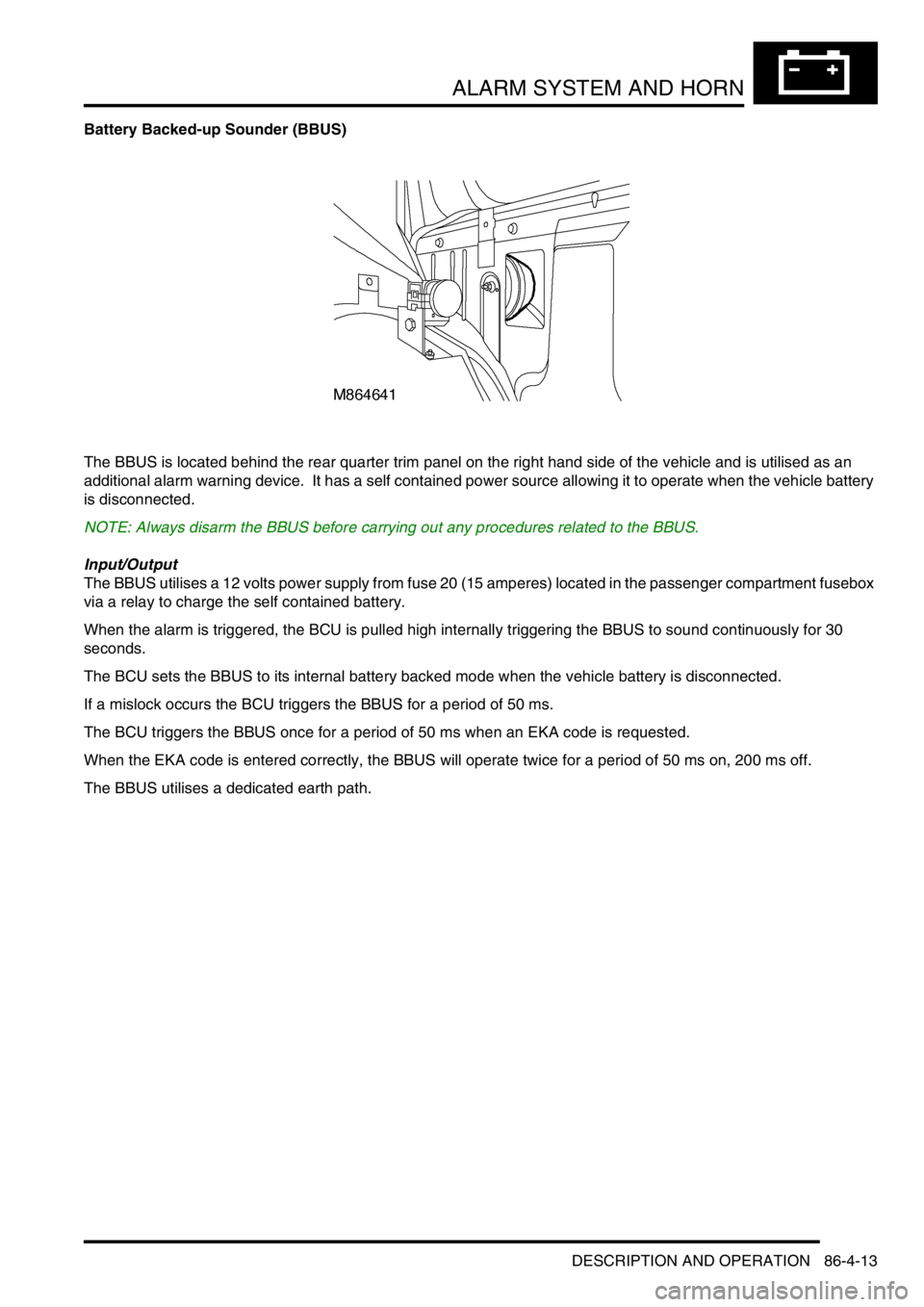
The BBUS is located behind the rear quarter trim panel on the right hand side of the vehicle and is utilised as an
additional alarm warning device. It has a self contained power source allowing it to operate when the vehicle battery
is disconnected.
NOTE: Always disarm the BBUS before carrying out any procedures related to the BBUS.
Input/Output
The BBUS utilises a 12 volts power supply from fuse 20 (15 amperes) located in the passenger compartment fusebox
via a relay to charge the self contained battery.
When the alarm is triggered, the BCU is pulled high internally triggering the BBUS to sound continuously for 30
seconds.
The BCU sets the BBUS to its internal battery backed mode when the vehicle battery is disconnected.
If a mislock occurs the BCU triggers the BBUS for a period of 50 ms.
The BCU triggers the BBUS once for a period of 50 ms when an EKA code is requested.
When the EKA code is entered correctly, the BBUS will operate twice for a period of 50 ms on, 200 ms off.
The BBUS utilises a dedicated earth path.
Page 1523 of 1672

ALARM SYSTEM AND HORN
86-4-14 DESCRIPTION AND OPERATION
Vehicle horn/alarm sounder
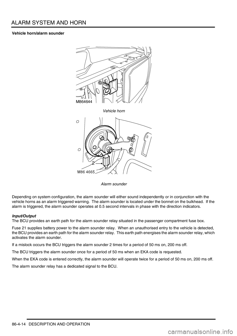
Vehicle horn
Alarm sounder
Depending on system configuration, the alarm sounder will either sound independently or in conjunction with the
vehicle horns as an alarm triggered warning. The alarm sounder is located under the bonnet on the bulkhead. If the
alarm is triggered, the alarm sounder operates at 0.5 second intervals in phase with the direction indicators.
Input/Output
The BCU provides an earth path for the alarm sounder relay situated in the passenger compartment fuse box.
Fuse 21 supplies battery power to the alarm sounder relay. When an unauthorised entry to the vehicle is detected,
the BCU provides an earth path for the alarm sounder relay. This earth path energises the alarm sounder relay, which
activates the alarm sounder.
If a mislock occurs the BCU triggers the alarm sounder 2 times for a period of 50 ms on, 200 ms off.
The BCU triggers the alarm sounder once for a period of 50 ms when an EKA code is requested.
When the EKA code is entered correctly, the alarm sounder will operate twice for a period of 50 ms on, 200 ms off.
The alarm sounder relay has a dedicated signal to the BCU.
Page 1524 of 1672

ALARM SYSTEM AND HORN
DESCRIPTION AND OPERATION 86-4-15
Anti-theft status LED
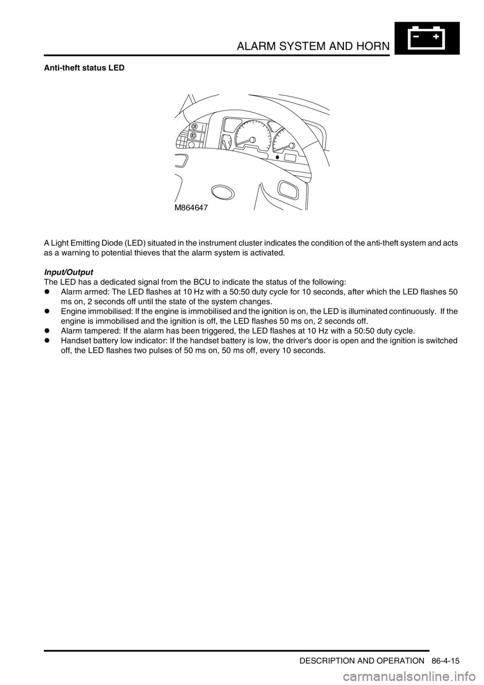
A Light Emitting Diode (LED) situated in the instrument cluster indicates the condition of the anti-theft system and acts
as a warning to potential thieves that the alarm system is activated.
Input/Output
The LED has a dedicated signal from the BCU to indicate the status of the following:
lAlarm armed: The LED flashes at 10 Hz with a 50:50 duty cycle for 10 seconds, after which the LED flashes 50
ms on, 2 seconds off until the state of the system changes.
lEngine immobilised: If the engine is immobilised and the ignition is on, the LED is illuminated continuously. If the
engine is immobilised and the ignition is off, the LED flashes 50 ms on, 2 seconds off.
lAlarm tampered: If the alarm has been triggered, the LED flashes at 10 Hz with a 50:50 duty cycle.
lHandset battery low indicator: If the handset battery is low, the driver's door is open and the ignition is switched
off, the LED flashes two pulses of 50 ms on, 50 ms off, every 10 seconds.
Page 1532 of 1672

ALARM SYSTEM AND HORN
DESCRIPTION AND OPERATION 86-4-23
Depending on which market the vehicle is sold, either the vehicle horn, a specific alarm sounder, or a BBUS operates
in phase with the direction indicators when the alarm is triggered. The audible warning device operates for
approximately 30 seconds at 0.25 second on, and 0.25 second off. The BCU allows the alarm to be triggered up to 3
times in any armed period.
Theft deterrent LED
An LED located in the instrument pack indicates the status of the alarm system.
There are eight theft deterrent alarm configurations:
lNo handset low battery warning.
lHandset low battery warning.
lNo passive immobilisation.
lPassive immobilisation.
lEngine immobilised (ignition off, LED off).
lEngine immobilised (ignition off, LED flashes).
lNo alarm tampered indication.
lAlarm tampered indication.
The theft deterrent LED utilises a particular flash to show the status of the following:
lAlarm armed.
lEngine immobilised.
lAlarm tampered.
lHandset low battery warning.
Transit mode
To prevent excessive battery drain during transportation to overseas markets, the vehicle is placed in a transit mode
at the end of line test.
The following functions are disabled when the vehicle is in transit mode:
lVolumetric sensors.
lPassive immobilisation.
lMobilisation of the vehicle by use of door lock.
lIgnition key interlock.
lElectric seat enable time-out with drivers door open.
To exit this mode, switch on the ignition and simultaneously hold down the heated rear window and the rear fog lamp
switch for 2 seconds.
Transit mode can be entered using Testbook.