2002 LAND ROVER DISCOVERY rear entertainment
[x] Cancel search: rear entertainmentPage 27 of 1672

CONTENTS
24 CONTENTS
Electric windows block diagram ...................................................................................................... 86-5-1
Electric windows component layout ................................................................................................ 86-5-2
Description ...................................................................................................................................... 86-5-4
Operation ....................................................................................................................................... 86-5-11
REPAIRS
Switch - rear door ......................................................................................................................... 86-5-13
Switch - console ............................................................................................................................ 86-5-13
Switch - heated rear screen ............................................................................................................ 86-5-14
IN CAR ENTERTAINMENT....................................................................... 86-6-1
DESCRIPTION AND OPERATION
ICE System Component layout....................................................................................................... 86-6-1
Base and mid line ICE system control diagram .............................................................................. 86-6-2
High line ICE system control diagram............................................................................................. 86-6-3
Description ...................................................................................................................................... 86-6-4
REPAIRS
Radio cassette player ..................................................................................................................... 86-6-13
Speaker - low/full range - front door ............................................................................................. 86-6-14
Speaker - low range - rear door ..................................................................................................... 86-6-14
Switches - remote control - ICE .................................................................................................... 86-6-15
Amplifier - aerial .............................................................................................................................. 86-6-15
Speaker - mid range - front door ................................................................................................... 86-6-16
Speaker - high range - rear door .................................................................................................. 86-6-16
Amplifier - power ........................................................................................................................... 86-6-17
Speaker - tail door ........................................................................................................................ 86-6-18
CD autochanger ............................................................................................................................ 86-6-18
HARNESSES ............................................................................................ 86-7-1
REPAIRS
Harness - injectors - diesel ............................................................................................................ 86-7-1
Harness - body ............................................................................................................................. 86-7-1
Harness - engine - V8 ..................................................................................................................... 86-7-8
Harness - engine - diesel ................................................................................................................ 86-7-13
Harness - main ............................................................................................................................. 86-7-16
DRIVING AIDS .......................................................................................... 86-8-1
DESCRIPTION AND OPERATION
Park Distance Control – Component Location................................................................................ 86-8-1
Park Distance Control – Control Diagram....................................................................................... 86-8-2
Description ...................................................................................................................................... 86-8-4
Operation ........................................................................................................................................ 86-8-10
REPAIRS
Control unit (ECU) - parking aid...................................................................................................... 86-8-13
Sounder - parking aid rear ............................................................................................................. 86-8-14
Sensor - parking aid - rear - inner ................................................................................................... 86-8-15
Sensor - parking aid - rear - outer .................................................................................................. 86-8-16
Page 33 of 1672

INTRODUCTION
01-4
HRW Heated Rear Window
HSLA High Strength Low Alloy
ht/HT High tension
IACV Idle Air Control Valve
IAT Intake Air Temperature
ICE In-Car Entertainment
i.dia. Internal diameter
IDM Intelligent Driver Module
IF Intermediate Frequency
in
3Cubic inch
ILT Inlet Throttle
IPW Injector Pulse Width
ISO International Organisation for
Standardisation
ITS Inflatable Tubular Structure
k Thousand
kg Kilogramme
kg/h Kilogrammes per hour
km Kilometre
km/h Kilometres per hour
kPa KiloPascal
KS Knock Sensor
lb(s) Pounds
lbf Pounds force
lbf.in Pounds force inches
lbf/in
2Pounds per square inch
lbf.ft Pounds force feet
λLambda
lc Low compression
LCD Liquid Crystal Display
LED Light Emitting Diode
LEV Low Emission Vehicle
LH Left-Hand
LHD Left-Hand Drive
LSM Light Switch Module
LVS Liquid Vapour Separator
mMetre
µMicro
MAF Mass Air Flow
MAP Manifold Absolute Pressure
MET Mechanical, Electrical and Trim
MFU Multi-Function Unit
MFL Multi-Function Logic
max. Maximum
MEMS Modular Engine Management
System
MIG Metal/Inert Gas
MIL Malfunction Indicator Lamp
MPa MegaPascal
MOSFET Metal Oxide Semiconductor Field
Effect Transistor
min. Minimum
- Minus (tolerance)
' Minute (angle)
mm Millimetre
mph Miles per hour MPi Multi-Point injection
MV Motorised Valve
MY Model Year
NAS North American Specification
(-) Negative (electrical)
Nm Newton metre
No. Number
NO
2Nitrogen Dioxide
NO
xOxides of Nitrogen
NTC Negative Temperature
Coefficient
NRV Non Return Valve
OBD On Board Diagnostics
OBM On Board Monitoring
o.dia. Outside diameter
OAT Organic Acid Technology
ORM Off-road Mode
ΩOhm
PAS Power Assisted Steering
PCB Printed Circuit Board
PCV Positive Crankcase Ventilation
PDC Parking Distance Control
PDOP Position Dilation Of Precision
PI Programme Information
PPS Pulse Per Second
PS Programme Service
psi Pounds per square inch
pts. Pints
% Percentage
+ Plus (tolerance) or Positive
(electrical)
±Plus or minus (tolerance)
PTC Positive Temperature Coefficient
PTFE Polytetrafluorethylene
PVC Polyvinyl chloride
PWM Pulse Width Modulation
RDS Radio Data Service
rRadius
:Ratio
ref Reference
REG Regionalisation
RES Rover Engineering Standards
rev/min Revolutions per minute
RF Radio Frequency
RGB Red / Green / Blue
RH Right-Hand
RHD Right-Hand Drive
ROM Read Only Memory
RON Research Octane Number
ROV Roll Over Valve
ROW Rest Of World
SAE Society of Automotive Engineers
SAI Secondary Air Injection
" Second (angle)
SLABS Self Levelling and Anti-Lock
Brake System
SLS Self Levelling Suspension
SOHC Single Overhead Camshaft
Page 1063 of 1672

BRAKES
70-18 DESCRIPTION AND OPERATION
The SLABS ECU continually calculates vehicle speed using the wheel speed inputs from all four ABS sensors. The
calculated vehicle speed is then used as a reference against which individual wheel speeds are monitored for
unacceptable acceleration or deceleration. The ABS sensor inputs are also used by the SLABS ECU to detect vehicle
deceleration rate, vehicle cornering rate and rough terrain.
The engaged forward gear and (on manual gearbox models) the clutch status are computed from the engine data
input, the engine speed input and vehicle speed. Reverse gear status is provided by an input from the reverse lamp
switch (manual gearbox models) or the BCU (automatic gearbox models). On automatic models, the BCU also
provides the neutral selected input.
In addition to controlling the brake related functions, the SLABS ECU:
lControls the operation of the self levelling suspension (SLS) system (where fitted).
+ REAR SUSPENSION, DESCRIPTION AND OPERATION, Description.
lOn V8 models, outputs a rough road signal to the ECM when traversing rough terrain.
lOutputs a vehicle speed signal.
The vehicle speed signal is output to the following systems (where fitted):
lActive Cornering Enhancement.
+ FRONT SUSPENSION, DESCRIPTION AND OPERATION, Description - ACE.
lAir conditioning.
+ AIR CONDITIONING, DESCRIPTION AND OPERATION, Description.
lCruise control.
+ ENGINE MANAGEMENT SYSTEM - Td5, DESCRIPTION AND OPERATION, Description.
+ ENGINE MANAGEMENT SYSTEM - V8, DESCRIPTION AND OPERATION, Description - engine
management.
lEngine management.
+ ENGINE MANAGEMENT SYSTEM - Td5, DESCRIPTION AND OPERATION, Description.
+ ENGINE MANAGEMENT SYSTEM - V8, DESCRIPTION AND OPERATION, Description - engine
management.
lIn-car entertainment.
+ IN CAR ENTERTAINMENT, DESCRIPTION AND OPERATION, Description.
lInstrument pack.
+ INSTRUMENTS, DESCRIPTION AND OPERATION, Description.
ABS sensors
The ABS sensors supply the SLABS ECU with a sinusoidal speed signal from each wheel. An inductive sensor,
installed in the hub bearing of each wheel, senses off a 60 tooth exciter ring integrated into the inner race of the hub
bearing. Each ABS sensor has a fly-lead connecting it to the vehicle wiring.
6 Shuttle valve switches Input
7 Rear left outlet solenoid valve Output
8 Rear left inlet solenoid valve Output
9 Centre differential lock switch Input
10 Rear right outlet solenoid valve Output
11 Rear right inlet solenoid valve Output
12 Brake lamp relay Output
15 Return pump relay Output
C0655
7 Audible warning Output
10 Engine speed Input
Connector and pins not listed are either not used or used by the self levelling suspension system.
+ REAR SUSPENSION, DESCRIPTION AND OPERATION, Description.
Connector/Pin No. Description Input/Output
Page 1132 of 1672

DOORS
REPAIRS 76-1-9
Trim casing - tail door
$% 76.34.09.99
Remove
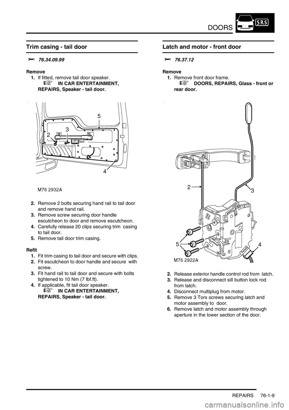
1.If fitted, remove tail door speaker.
+ IN CAR ENTERTAINMENT,
REPAIRS, Speaker - tail door.
2.Remove 2 bolts securing hand rail to tail door
and remove hand rail.
3.Remove screw securing door handle
escutcheon to door and remove escutcheon.
4.Carefully release 20 clips securing trim casing
to tail door.
5.Remove tail door trim casing.
Refit
1.Fit trim casing to tail door and secure with clips.
2.Fit escutcheon to door handle and secure with
screw.
3.Fit hand rail to tail door and secure with bolts
tightened to 10 Nm (7 lbf.ft).
4.If applicable, fit tail door speaker.
+ IN CAR ENTERTAINMENT,
REPAIRS, Speaker - tail door.
Latch and motor - front door
$% 76.37.12
Remove
1.Remove front door frame.
+ DOORS, REPAIRS, Glass - front or
rear door.
2.Release exterior handle control rod from latch.
3.Release and disconnect sill button lock rod
from latch.
4.Disconnect multiplug from motor.
5.Remove 3 Torx screws securing latch and
motor assembly to door.
6.Remove latch and motor assembly through
aperture in the lower section of the door.
Page 1162 of 1672

INTERIOR TRIM COMPONENTS
REPAIRS 76-3-9
16.Remove console.
NOTE: Do not carry out further dismantling if
component is removed for access only.
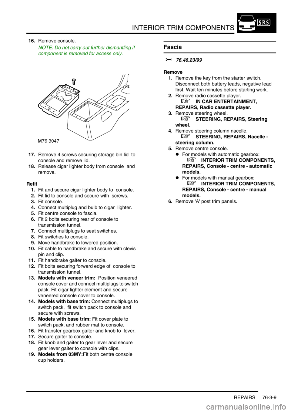
17.Remove 4 screws securing storage bin lid to
console and remove lid.
18.Release cigar lighter body from console and
remove.
Refit
1.Fit and secure cigar lighter body to console.
2.Fit lid to console and secure with screws.
3.Fit console.
4.Connect multiplug and bulb to cigar lighter.
5.Fit centre console to fascia.
6.Fit 2 bolts securing rear of console to
transmission tunnel.
7.Connect multiplugs to seat switches.
8.Fit switches to console.
9.Move handbrake to lowered position.
10.Fit cable to handbrake and secure with clevis
pin and clip.
11.Fit handbrake gaiter to console.
12.Fit bolts securing forward edge of console to
transmission tunnel.
13. Models with veneer trim: Position veneered
console cover and connect multiplugs to switch
pack. Fit cigar lighter element and secure
veneered console cover to console.
14. Models with base trim: Connect multiplugs to
switch pack, fit switch pack to console and
secure with screws.
15. Models with base trim: Fit cover plate to
switch pack, and rubber mat to console.
16.Fit transfer gearbox gaiter and knob to lever.
17.Secure gaiter to console.
18.Fit knob and gaiter to gear lever and secure
gear lever gaiter to console with clips.
19. Models from 03MY:Fit both centre console
cup holders.
Fascia
$% 76.46.23/99
Remove
1.Remove the key from the starter switch.
Disconnect both battery leads, negative lead
first. Wait ten minutes before starting work.
2.Remove radio cassette player.
+ IN CAR ENTERTAINMENT,
REPAIRS, Radio cassette player.
3.Remove steering wheel.
+ STEERING, REPAIRS, Steering
wheel.
4.Remove steering column nacelle.
+ STEERING, REPAIRS, Nacelle -
steering column.
5.Remove centre console.
lFor models with automatic gearbox:
+ INTERIOR TRIM COMPONENTS,
REPAIRS, Console - centre - automatic
models.
lFor models with manual gearbox:
+ INTERIOR TRIM COMPONENTS,
REPAIRS, Console - centre - manual
models.
6.Remove 'A' post trim panels.
Page 1171 of 1672

INTERIOR TRIM COMPONENTS
76-3-18 REPAIRS
Refit
1.With assistance position carpet.
2.Secure main body harness to transmission
tunnel with nuts.
3.Position front carpet retainers and secure to
floor with screws.
4.Fit finishers to front carpet retainers
5.Fit both lower 'A' post trim panels.
6.Fit centre console.
lFor models with manual gearbox:
+ INTERIOR TRIM COMPONENTS,
REPAIRS, Console - centre - manual
models.
lFor models with automatic gearbox:
+ INTERIOR TRIM COMPONENTS,
REPAIRS, Console - centre - automatic
models.
7. Models with premium ICE: Fit CD
autochanger.
+ IN CAR ENTERTAINMENT,
REPAIRS, CD autochanger.
8. Models with premium ICE: Fit power
amplifier.
+ IN CAR ENTERTAINMENT,
REPAIRS, Amplifier - power.
Carpet - rear
$% 76.49.03
Remove
1. Models with premium ICE: Remove power
amplifier.
+ IN CAR ENTERTAINMENT,
REPAIRS, Amplifier - power.
2.Remove RH front seat.
+ SEATS, REPAIRS, Seat - front.
3.Remove both 'B' post lower trim panels.
+ INTERIOR TRIM COMPONENTS,
REPAIRS, Trim casing - lower - 'B' post.
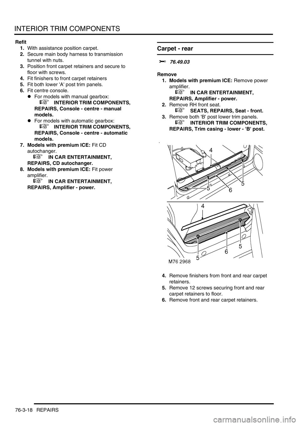
4.Remove finishers from front and rear carpet
retainers.
5.Remove 12 screws securing front and rear
carpet retainers to floor.
6.Remove front and rear carpet retainers.
Page 1172 of 1672

INTERIOR TRIM COMPONENTS
REPAIRS 76-3-19
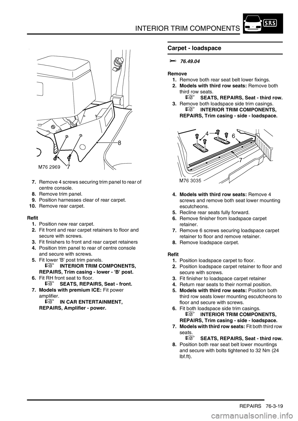
7.Remove 4 screws securing trim panel to rear of
centre console.
8.Remove trim panel.
9.Position harnesses clear of rear carpet.
10.Remove rear carpet.
Refit
1.Position new rear carpet.
2.Fit front and rear carpet retainers to floor and
secure with screws.
3.Fit finishers to front and rear carpet retainers
4.Position trim panel to rear of centre console
and secure with screws.
5.Fit lower 'B' post trim panels.
+ INTERIOR TRIM COMPONENTS,
REPAIRS, Trim casing - lower - 'B' post.
6.Fit RH front seat to floor.
+ SEATS, REPAIRS, Seat - front.
7. Models with premium ICE: Fit power
amplifier.
+ IN CAR ENTERTAINMENT,
REPAIRS, Amplifier - power.
Carpet - loadspace
$% 76.49.04
Remove
1.Remove both rear seat belt lower fixings.
2. Models with third row seats: Remove both
third row seats.
+ SEATS, REPAIRS, Seat - third row.
3.Remove both loadspace side trim casings.
+ INTERIOR TRIM COMPONENTS,
REPAIRS, Trim casing - side - loadspace.
4. Models with third row seats: Remove 4
screws and remove both seat lower mounting
escutcheons.
5.Recline rear seats fully forward.
6.Remove finisher from loadspace carpet
retainer.
7.Remove 6 screws securing loadspace carpet
retainer to floor and remove retainer.
8.Remove loadspace carpet.
Refit
1.Position loadspace carpet to floor.
2.Position loadspace carpet retainer to floor and
secure with screws.
3.Fit finisher to loadspace carpet retainer
4.Return rear seats to their normal position.
5. Models with third row seats: Position both
third row seats lower mounting escutcheons to
floor and secure with screws.
6.Fit both loadspace side trim casings.
+ INTERIOR TRIM COMPONENTS,
REPAIRS, Trim casing - side - loadspace.
7. Models with third row seats: Fit both third row
seats.
+ SEATS, REPAIRS, Seat - third row.
8.Position both rear seat belt lower mountings
and secure with bolts tightened to 32 Nm (24
lbf.ft).
Page 1283 of 1672

PANEL REPAIRS
77-2-34 REPAIRS
Refit
1.Fit windscreen side finisher.
+ EXTERIOR FITTINGS, REPAIRS,
Side finisher - windscreen.
2.Fit insulation pad to engine bulkhead.
3.Fit front mud flap.
4.Fit road wheel and tighten nuts to 140 Nm (103
lbf.ft).
5.Fit wiring harness to valance assembly.
6. Models with A/C: Fit A/C pipes to valance
assembly.
7.Fit PAS/ACE reservoir.
8.Fit brake pipes to valance assembly.
9. LHD models: Fit brake servo.
+ BRAKES, REPAIRS, Servo - brake.
10.Fit ABS modulator unit.
+ BRAKES, REPAIRS, Modulator unit
- ABS.
11.Fit front bulkhead assembly.
+ PANEL REPAIRS, REPAIRS, Front
bulkhead assembly.
12.Connect leads/multiplug to alternator.
13.Connect battery leads, negative lead last.
'A' post assembly
In this procedure, the front wing and the valance
outer reinforcement (rear section) are replaced in
conjunction with the 'A' post assembly. The dash side
assembly can also be replaced in this procedure if
required.
Remove
1.Disconnect both battery leads, negative lead
first.
2.Disconnect leads/multiplug from alternator.
3.Remove bonnet.
4.Remove front wing.
+ EXTERIOR FITTINGS, REPAIRS,
Wing - front - up to 03MY.
5.Remove RH or LH front door.
+ DOORS, REPAIRS, Door - front.
6.Remove RH or LH sill finisher.
7.Remove windscreen.
+ SCREENS, REPAIRS, Windscreen.
8. Diesel models: Remove ECM.
+ ENGINE MANAGEMENT SYSTEM -
Td5, REPAIRS, Engine control module
(ECM).
9.Remove RH or LH 'A' post inner finishers and
disconnect speaker multiplug (if fitted).
10.Release sunroof drain tube and position aside.
11.Remove RH or LH front seat.
+ SEATS, REPAIRS, Seat - front.
12. RH side: Remove CD autochanger.
+ IN CAR ENTERTAINMENT,
REPAIRS, CD autochanger.
13.Remove fascia.
+ INTERIOR TRIM COMPONENTS,
REPAIRS, Fascia.
14. Driver's side: Remove steering column
support bracket.
15.Remove relevant wiring from 'A' post.
16.Remove tread plate from front door aperture.
17.Release front carpet and position aside.
18.Remove front door aperture seal.
19.Remove engine bulkhead insulation.