2002 LAND ROVER DISCOVERY battery
[x] Cancel search: batteryPage 1559 of 1672

IN CAR ENTERTAINMENT
86-6-6 DESCRIPTION AND OPERATION
Midline system radio cassette
The midline radio cassette is located in the center of the fascia and contains the radio and tape player, four clips
(accessible through holes in the front of the unit) secure the unit. To remove the radio cassette unit the four clips
must be released with a special tool. The midline system can be controlled from the fascia mounted radio cassette,
or from remote radio control switches on the left hand side of the steering wheel. The audio signal can be from the
radio, cassette player or a optional CD-autochanger. A logic control circuit in the radio cassette player controls the
operation in the various control modes.
The radio cassette has a display screen, information shown can include current status, station (radio mode) or
cassette tape track or (optional) CD-autochanger track/disc status. Power for illumination on the radio cassette is
supplied from the passenger compartment fusebox. A main fuse is also located in the connector socket area on the
back of the radio cassette.
Security code function
A combination of buttons on the radio cassette are used to input and change security codes. Security codes make the
unit unusable if the unit is disconnected from the vehicle without deactivating the security code. The radio cassette
has an internal memory chip that stores the information, if the power is removed from the unit the chip will activate the
security code feature. For this reason the security code feature must be deactivated before the unit is removed or the
vehicles battery is disconnected.
Audio functions
A rotary knob allows changes of levels or selections during the various modes of operation, this includes volume,
bass, treble and fader.
Cassette functions
The radio cassette has buttons for the following cassette functions eject, tape, reverse, forward, tape eject/reversal.
Radio functions
The radio cassette has buttons for the selection of AM or FM reception. Selection of the radio station is controlled by
the use of the multi-function buttons on the radio cassette player, the radio headphone amplifiers or the remote radio
controls on the steering wheel.
Traffic information and news function
A traffic information button (TA/NEWS) allows traffic or news information to be selected on the FM waveband only, in
this mode the audio output will mute when traffic or news messages are received. After the traffic or news message
the radio, cassette tape or CD will resume play, the traffic and news information varies with the country of use and
radio band selected.
8 I-BUS communications Input/Output
9 Audio amplifier spatial imaging enable Output
10 Radio headphone LH remote control Input
11 Radio headphone RH remote control Input
12 Headphone remote controls feed Output
C1354 (high line systems)
13 CD-autochanger audio left channel Input +
14 CD-autochanger audio right channel Input +
15 CD-autochanger audio earth Output
16 CD-autochanger audio left channel Input -
17 CD-autochanger audio right channel Input -
18 Not Used
19 CD-autochanger I-BUS communications link Input/Output
20 CD-autochanger permanent feed Output
Page 1560 of 1672

IN CAR ENTERTAINMENT
DESCRIPTION AND OPERATION 86-6-7
Multi function buttons
Rotary controls are located on the front of the radio cassette for adjustment of bass, treble etc, depending on current
mode selected. Operation of presets 1-6 depends on current mode of operation and allows selection of radio band
(Radio mode on) or CD-autochanger disc (in the CD mode). Scan (Mode dependent) manual or automatic selection
of band or track. RND random play, MODE/MUTE (mode dependent) when pressed the button allows manual
operation or alternate mode selections such as manual tuning, compact disk cue/review, tape forward/rewind modes.
Internal memory
An internal memory chip stores the station presets and security code, power is supplied internally to the chip via a
permanent power feed, supplied from the passenger compartment fuse box.
High line system radio cassette
The high line radio cassette is located in the center of the fascia and contains the radio and tape player. Two clips
(accessible through slots in the front of the unit) secure the unit. To remove the radio cassette unit the two clips must
be released with a special tool. The high line system can be controlled from the fascia mounted radio cassette, or from
remote radio control switches on the left hand side of the steering wheel. In vehicles fitted with radio headphone
amplifiers, the rear seat passengers can control their individual audio output using a headphone amplifier control
panel. The audio signal can be from the radio, cassette player or a CD-autochanger. A logic control circuit in the radio
cassette player controls the operation in the various control modes.
The radio cassette has a display screen, information shown includes current status, station (Radio mode) , CD-
autochanger track/disc status or status of headphone amplifier. Power for illumination on the radio cassette is supplied
from the passenger compartment fusebox. A main fuse is also located in the connector socket area on the back of
the radio cassette. When the radio cassette switch is on, power is made available via internal circuits to the radio
headphone amplifiers.
Security code function
A combination of buttons on the radio cassette are used to input and change security codes. Security codes make the
unit unusable if the unit is disconnected from the vehicle without deactivating the security code. The radio cassette
has an internal memory chip that stores the information, if the power is removed from the unit the chip will activate the
security code feature. For this reason the security code feature must be deactivated before the unit is removed or the
vehicles battery is disconnected.
Audio functions
A rotary knob allows changes of levels or selections during the various modes of operation, this includes volume,
bass, treble, fader and spatial on/off.
Cassette functions
The radio cassette has buttons for the following cassette functions; eject, fast forward, rewind and dolby. The dolby
symbol is shown on the dot matrix display screen if dolby mode is selected.
Radio functions
The radio cassette has buttons for the selection of AM or FM reception. Selection of the radio station is controlled by
the use of the multi-function buttons on the radio cassette player, the radio headphone amplifiers or the remote radio
controls on the steering wheel.
CD-autochanger functions
The CD button on the radio cassette player allows selection of the CD-autochanger. CD disc and track selection is
controlled by the use of the multi-function buttons on the radio cassette player, the radio headphone amplifiers or the
remote radio controls on the steering wheel.
Page 1562 of 1672

IN CAR ENTERTAINMENT
DESCRIPTION AND OPERATION 86-6-9
Inputs and outputs
The radio cassette player receives a mute signal from the telephone system if a call is received, when the call finishes
the mute is removed and the system resumes play. Inputs are also received from the steering wheel control system
(mid line and high line sytems). When the system is turned on, the high line systems radio cassette player:
lsends a 'power on enable' to the power amplifier
lsends an 'enable' signal to the radio headphone amplifiers.
On the high line system the radio cassette player also sends and receives signals from the CD-autochanger and rear
headphone amplifiers (if fitted). On high line systems the radio cassette player sends audio signals to the power
amplifier.
C0098
1 Telephone mute Input
2 Steering wheel remote radio controls Input
3 Steering wheel remote radio controls Output
4 Permanent battery feed Input
5 System enable Output
6 Illumination Input
7 Auxilary feed Input
8EarthInput
C0921 (high line systems)
1 Radio headphone left channel Output +
2 Radio headphone right channel Output +
3 Telephone audio Input +
4 Radio headphone left channel Output -
5 Radio headphone right channel Output -
6 Telephone audio Input -
C0922 (high line systems)
7 Radio headphone active Input
8 I-BUS communications Input/Output
9 Audio amplifier spatial imaging enable Output
10 Radio headphone LH remote control Input
11 Radio headphone RH remote control Input
12 Headphone remote controls feed Output
C1354 (high line systems)
13 CD-autochanger audio left channel Input +
14 CD-autochanger audio right channel Input +
15 CD-autochanger audio earth Output
16 CD-autochanger audio left channel Input -
17 CD-autochanger audio right channel Input -
18 Not Used
19 CD-autochanger I-BUS communications link Input/Output
20 CD-autochanger permanent feed Output
Page 1568 of 1672

IN CAR ENTERTAINMENT
REPAIRS 86-6-15
Switches - remote control - ICE
$% 86.50.13
Remove
1.Remove the key from the starter switch.
Disconnect both battery leads, negative lead
first. Wait ten minutes before starting work.
2.Remove driver's airbag module.
+ RESTRAINT SYSTEMS, REPAIRS,
Airbag module - drivers.
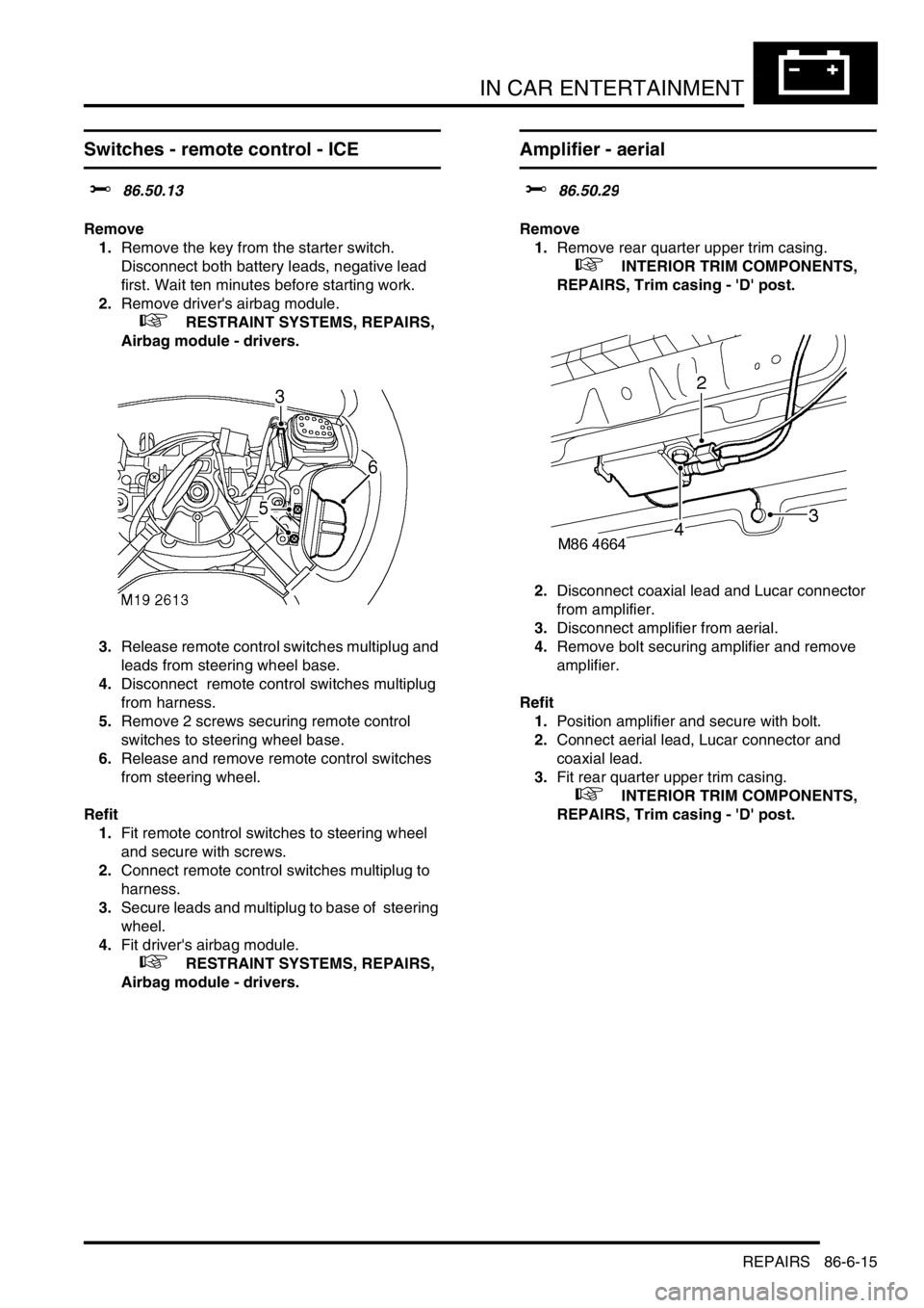
3.Release remote control switches multiplug and
leads from steering wheel base.
4.Disconnect remote control switches multiplug
from harness.
5.Remove 2 screws securing remote control
switches to steering wheel base.
6.Release and remove remote control switches
from steering wheel.
Refit
1.Fit remote control switches to steering wheel
and secure with screws.
2.Connect remote control switches multiplug to
harness.
3.Secure leads and multiplug to base of steering
wheel.
4.Fit driver's airbag module.
+ RESTRAINT SYSTEMS, REPAIRS,
Airbag module - drivers.
Amplifier - aerial
$% 86.50.29
Remove
1.Remove rear quarter upper trim casing.
+ INTERIOR TRIM COMPONENTS,
REPAIRS, Trim casing - 'D' post.
2.Disconnect coaxial lead and Lucar connector
from amplifier.
3.Disconnect amplifier from aerial.
4.Remove bolt securing amplifier and remove
amplifier.
Refit
1.Position amplifier and secure with bolt.
2.Connect aerial lead, Lucar connector and
coaxial lead.
3.Fit rear quarter upper trim casing.
+ INTERIOR TRIM COMPONENTS,
REPAIRS, Trim casing - 'D' post.
Page 1570 of 1672

IN CAR ENTERTAINMENT
REPAIRS 86-6-17
Amplifier - power
$% 86.50.36
Remove
1.Release fixings and remove battery cover.
2.Disconnect battery earth lead.
3.Remove 3 screws and 1 trim clip securing lower
trim casing to LH front seat.
4.Remove lower trim casing.
5.Move seat fully rearwards.
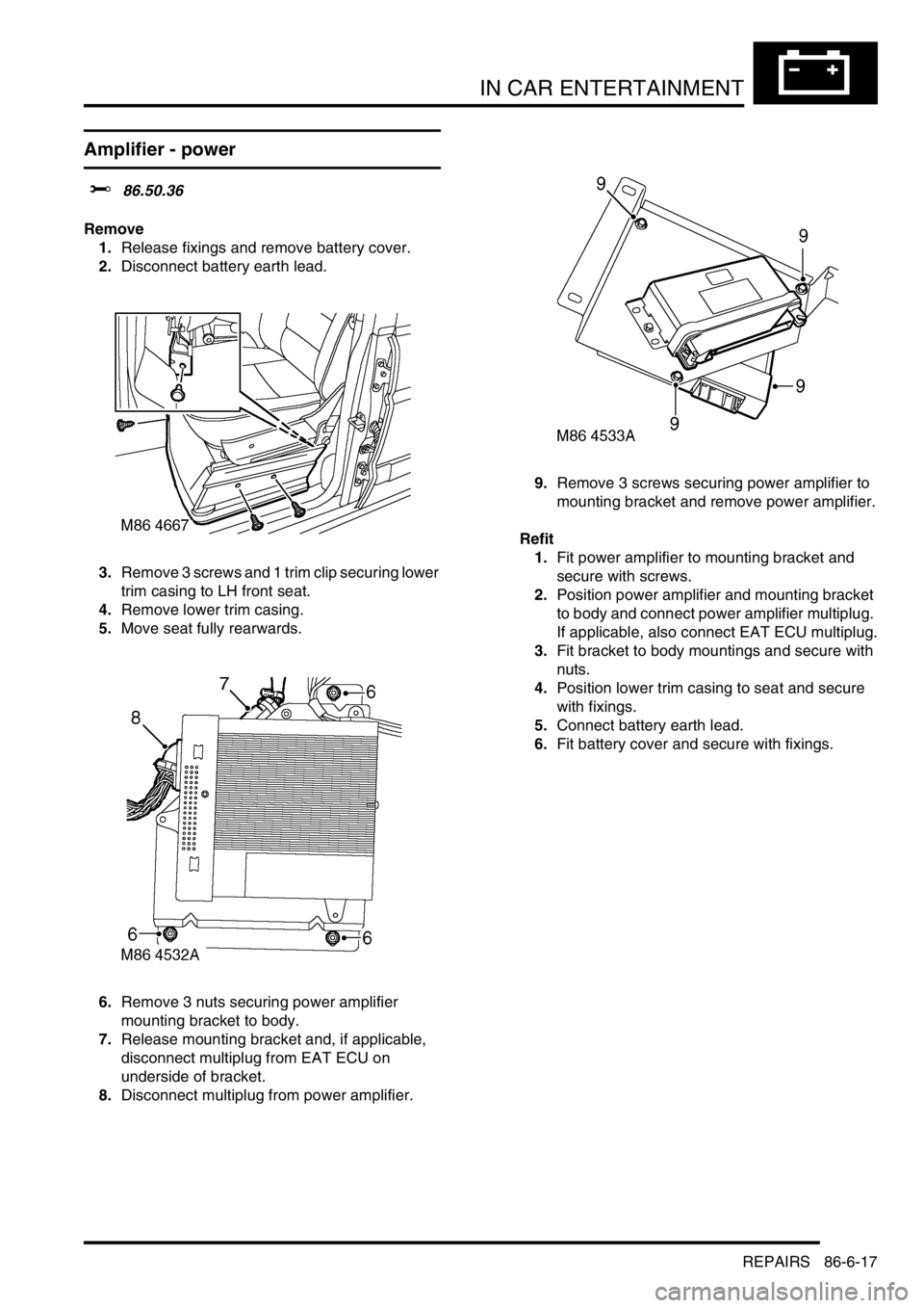
6.Remove 3 nuts securing power amplifier
mounting bracket to body.
7.Release mounting bracket and, if applicable,
disconnect multiplug from EAT ECU on
underside of bracket.
8.Disconnect multiplug from power amplifier. 9.Remove 3 screws securing power amplifier to
mounting bracket and remove power amplifier.
Refit
1.Fit power amplifier to mounting bracket and
secure with screws.
2.Position power amplifier and mounting bracket
to body and connect power amplifier multiplug.
If applicable, also connect EAT ECU multiplug.
3.Fit bracket to body mountings and secure with
nuts.
4.Position lower trim casing to seat and secure
with fixings.
5.Connect battery earth lead.
6.Fit battery cover and secure with fixings.
Page 1581 of 1672

HARNESSES
86-7-10 REPAIRS
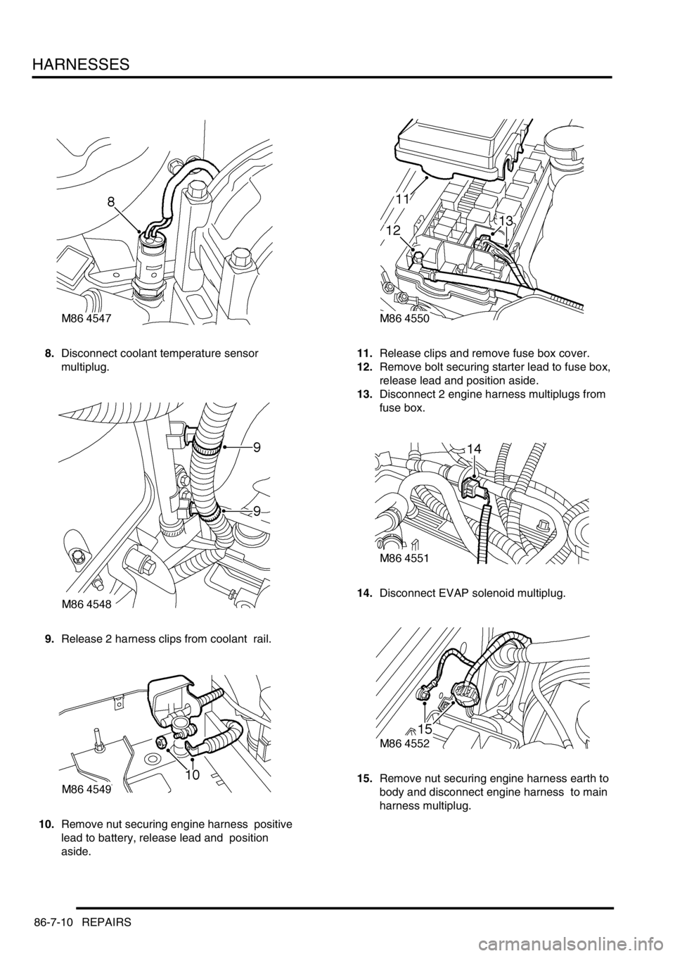
8.Disconnect coolant temperature sensor
multiplug.
9.Release 2 harness clips from coolant rail.
10.Remove nut securing engine harness positive
lead to battery, release lead and position
aside. 11.Release clips and remove fuse box cover.
12.Remove bolt securing starter lead to fuse box,
release lead and position aside.
13.Disconnect 2 engine harness multiplugs from
fuse box.
14.Disconnect EVAP solenoid multiplug.
15.Remove nut securing engine harness earth to
body and disconnect engine harness to main
harness multiplug.
Page 1582 of 1672

HARNESSES
REPAIRS 86-7-11
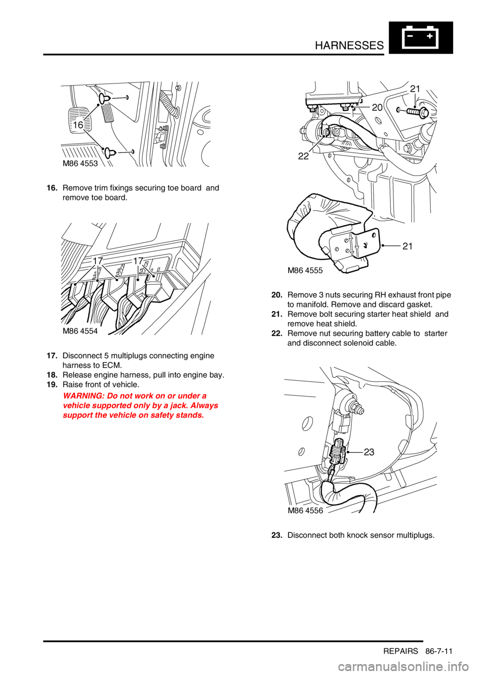
16.Remove trim fixings securing toe board and
remove toe board.
17.Disconnect 5 multiplugs connecting engine
harness to ECM.
18.Release engine harness, pull into engine bay.
19.Raise front of vehicle.
WARNING: Do not work on or under a
vehicle supported only by a jack. Always
support the vehicle on safety stands.20.Remove 3 nuts securing RH exhaust front pipe
to manifold. Remove and discard gasket.
21.Remove bolt securing starter heat shield and
remove heat shield.
22.Remove nut securing battery cable to starter
and disconnect solenoid cable.
23.Disconnect both knock sensor multiplugs.
Page 1583 of 1672

HARNESSES
86-7-12 REPAIRS
24.Remove bolt securing harness clip to LH side of
engine.
25.Disconnect camshaft sensor and oil pressure
switch multiplugs.
26.Remove engine harness. Refit
1.Position engine harness around engine.
2.Connect oil pressure switch and camshaft
sensor multiplugs.
3.Fit and tighten bolt securing harness to LH side
of engine.
4.Connect both knock sensor multiplugs.
5.Connect battery cable and solenoid cable to
starter motor.
6.Position starter heat shield and secure with
bolt.
7.Clean exhaust flange mating faces, using a
new gasket align exhaust fit nuts and tighten to
60 Nm (44 lbf.ft).
8.Remove stand(s) and lower vehicle.
9.Position harness into footwell and secure
grommet.
10.Connect ECM multiplugs.
11.Position toe board and secure with trim fixings.
12.Connect engine harness to main harness
multiplug and secure earth lead.
13.Connect EVAP solenoid multiplug.
14.Connect both fuse box multiplugs.
15.Position starter lead to fuse box and secure
screw.
16.Fit fuse box cover.
17.Position battery positive lead to battery and
secure nut.
18.Secure harness to coolant rail.
19.Position alternator cables and tighten terminal
B+ to 18 Nm (13 lbf.ft) and terminal D+ to 5 Nm
(3.7 lbf.ft)
20.Connect coolant temperature sensor multiplug.
21.Connect A/C compressor multiplug.
22.Secure harness clip to rear of LH cylinder head.
23.Connect CKP sensor multiplug.
24.Secure injector harness and connect injector
multiplugs.
25.Connect coil multiplugs.
26.Connect and secure HS
2O sensor multiplug
27.Fit upper inlet manifold.
+ MANIFOLDS AND EXHAUST
SYSTEMS - V8, REPAIRS, Gasket - inlet
manifold - upper - Without Secondary Air
Injection.
28.Connect battery earth lead.