Page 1071 of 1672

BRAKES
70-26 DESCRIPTION AND OPERATION
Description
General
The handbrake consists of a drum brake, installed on the rear of the transfer box, operated by a cable connected to
a handbrake lever between the front seats.
Handbrake lever
The handbrake lever is mounted on a base plate which attaches to the transmission tunnel. A conventional ratchet
and thumb operated release button are incorporated for locking and unlocking the lever. A warning switch on the base
of the lever operates the brake warning lamp in the instrument pack. While the handbrake is applied the warning
switch connects an earth to the instrument pack which, if the ignition is on, illuminates the brake warning lamp. In
some markets, the instrument pack performs a bulb check of the brake warning lamp each time the ignition is switched
on.
Cable
The handbrake cable consists of inner and outer cables installed between the handbrake lever and the drum brake.
A protective sleeve is installed on the cable to protect the cable from heat from the exhaust system. Handbrake
adjustment is provided by a threaded sleeve installed on the outer cable where it locates in the handbrake lever.
Turning an adjuster wheel, which is keyed to the threaded sleeve and secured by a 'C' clip, alters the effective length
of the outer sleeve and consequently changes the handbrake lever movement needed to apply the drum brake.
Page 1074 of 1672

BRAKES
ADJUSTMENTS 70-29
ADJUST ME NTS
Handbrake
$% 70.45.09
Check
1.Apply the handbrake lever 3 notches on the
ratchet. The handbrake should be fully
operational.
2.If the handbrake is not fully operational, the
brake shoes and/or the handbrake cable need
adjusting.
Adjust
1.Raise rear of vehicle.
WARNING: Do not work on or under a
vehicle supported only by a jack. Always
support the vehicle on safety stands.
2.Ensure handbrake lever is fully released.
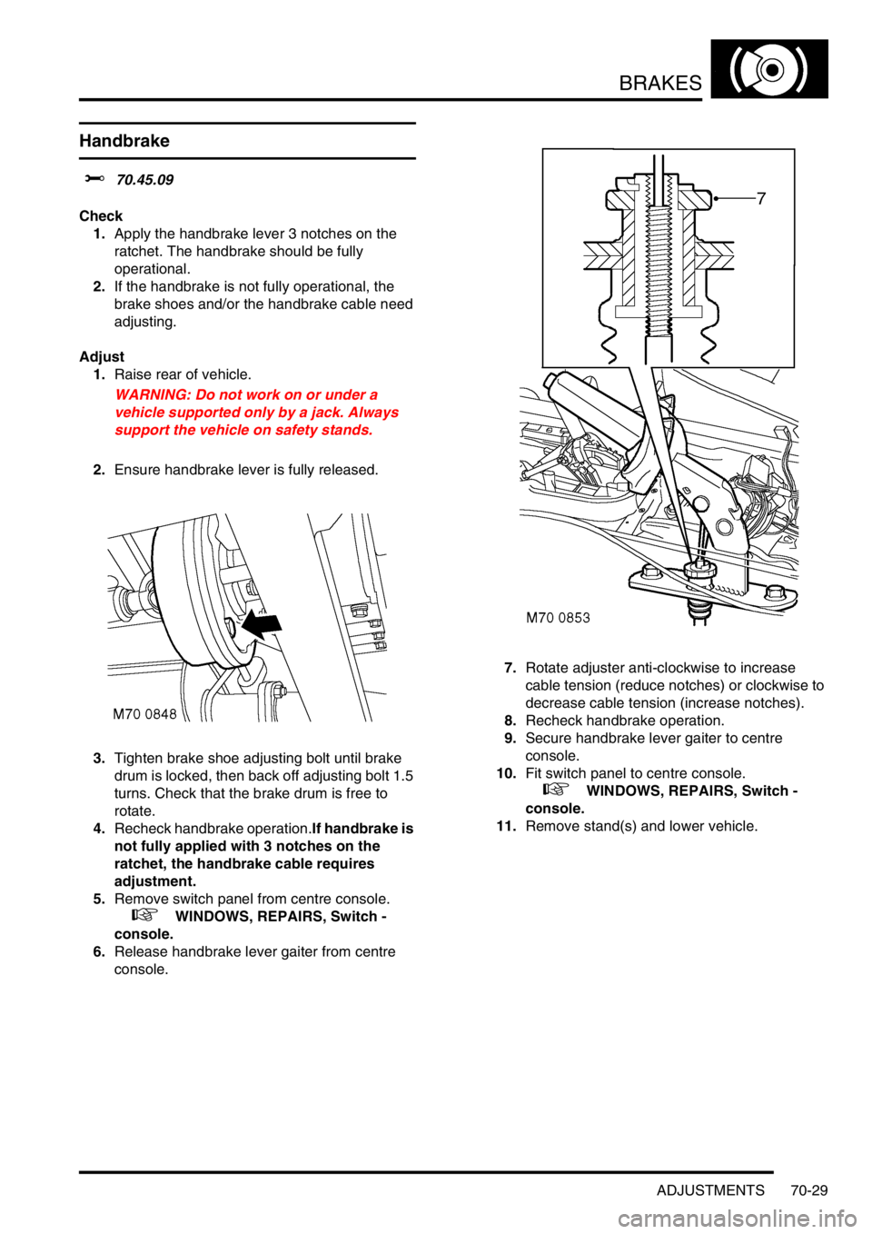
3.Tighten brake shoe adjusting bolt until brake
drum is locked, then back off adjusting bolt 1.5
turns. Check that the brake drum is free to
rotate.
4.Recheck handbrake operation.If handbrake is
not fully applied with 3 notches on the
ratchet, the handbrake cable requires
adjustment.
5.Remove switch panel from centre console.
+ WINDOWS, REPAIRS, Switch -
console.
6.Release handbrake lever gaiter from centre
console.7.Rotate adjuster anti-clockwise to increase
cable tension (reduce notches) or clockwise to
decrease cable tension (increase notches).
8.Recheck handbrake operation.
9.Secure handbrake lever gaiter to centre
console.
10.Fit switch panel to centre console.
+ WINDOWS, REPAIRS, Switch -
console.
11.Remove stand(s) and lower vehicle.
Page 1075 of 1672

BRAKES
70-30 ADJUSTMENTS
Brake system bleeding
$% 70.25.02
Bleeding of the brake system can be carried out
using the procedures given on TestBook, or by
following the manual procedure given below.
WARNING: If any components upstream of brake
modulator, including the modulator itself are
replaced, the brake system must be bled using
the procedure on TestBook/T4, to ensure that all
air is expelled from the new component(s).
WARNING: Do not allow brake fluid to come into
contact with eyes or skin.
Bleed
NOTE: This procedure covers bleeding the
complete system, but where only the primary or
secondary circuit have been disturbed in
isolation, it should only be necessary to bleed
that circuit. Partial bleeding of the hydraulic
system is only permissible if a brake pipe or
hose has been disconnected with only minor
loss of fluid.
1.Do not allow fluid level in master cylinder to fall
below 'MIN' mark during bleeding.
2.Do not fill reservoir above 'MAX' level.
3.Raise front and rear of vehicle.
WARNING: Do not work on or under a
vehicle supported only by a jack. Always
support the vehicle on safety stands.
4.Check all pipe and hose connections are tight
and there are no signs of leakage.
5.Top-up fluid level in brake reservoir to 'MAX'
mark.
WARNING: Do not allow dirt or foreign
liquids to enter the reservoir. Use only new
DOT 4 brake fluid from airtight containers.
Do not mix brands of brake fluid as they
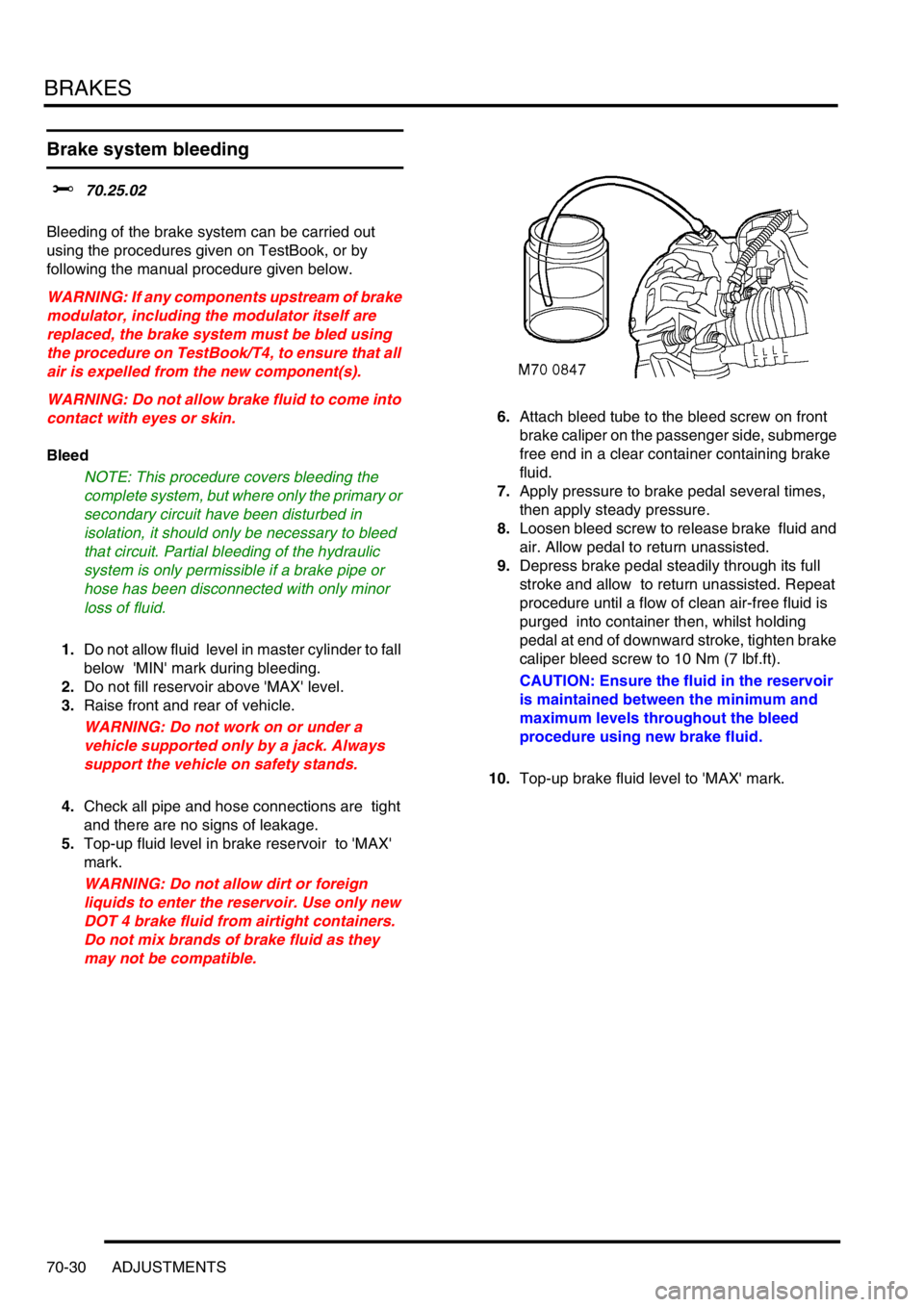
may not be compatible.6.Attach bleed tube to the bleed screw on front
brake caliper on the passenger side, submerge
free end in a clear container containing brake
fluid.
7.Apply pressure to brake pedal several times,
then apply steady pressure.
8.Loosen bleed screw to release brake fluid and
air. Allow pedal to return unassisted.
9.Depress brake pedal steadily through its full
stroke and allow to return unassisted. Repeat
procedure until a flow of clean air-free fluid is
purged into container then, whilst holding
pedal at end of downward stroke, tighten brake
caliper bleed screw to 10 Nm (7 lbf.ft).
CAUTION: Ensure the fluid in the reservoir
is maintained between the minimum and
maximum levels throughout the bleed
procedure using new brake fluid.
10.Top-up brake fluid level to 'MAX' mark.
Page 1076 of 1672
BRAKES
ADJUSTMENTS 70-31
Bleed sequence LHD
Bleed sequence RHD
11.Working in the sequence illustrated, repeat
steps 5 to 9 on remaining calipers.
WARNING: Braking efficiency may be
seriously impaired if the incorrect bleed
sequence is used.
12. Apply brakes and check for leakage.
13.Remove stand(s) and lower vehicle.
14.Road test vehicle. Check brake pedal for short
firm travel when brakes are applied.
Page 1078 of 1672
BRAKES
REPAIRS 70-33
REPAIRS
Brake disc - front
$% 70.12.10
Brake discs must be renewed in pairs, unless
one disc requires changing before 1000 miles
(1500 km) from new.
Remove
1.Raise front of vehicle.
WARNING: Do not work on or under a
vehicle supported only by a jack. Always
support the vehicle on safety stands.
2.Remove road wheel(s).
3.Remove 2 bolts securing brake caliper to
swivel hub.
4.Release caliper and tie aside clear of brake
disc.
CAUTION: Do not allow caliper to hang on
brake hose.
5.Remove screw securing disc to drive flange.
6.Remove brake disc from drive flange Refit
1.Clean mating faces of drive flange and new
disc.
2.Fit brake disc to drive flange, fit screw and
tighten to 13 Nm (10 lbf.ft).
3.Clean mating faces of caliper and hub.
4.Fit caliper, and tighten bolts to 175 Nm (129
lbf.ft).
5.Fit road wheel(s) and tighten nuts to 140 Nm
(103 lbf.ft).
6.Remove stand(s) and lower vehicle.
Page 1079 of 1672
BRAKES
70-34 REPAIRS
Brake disc - rear
$% 70.12.33
Brake discs must be renewed in pairs, unless
one disc requires changing before 1000 miles
(1500 km) from new.
Remove
1.Raise rear of vehicle.
WARNING: Do not work on or under a
vehicle supported only by a jack. Always
support the vehicle on safety stands.
2.Remove road wheel(s).
3.Remove 2 bolts securing brake caliper to rear
hub.
4.Release caliper and tie aside clear of brake
disc.
CAUTION: Do not allow caliper to hang on
brake hose.
5.Remove screw securing disc to drive flange.
6.Remove brake disc from drive flange. Refit
1.Clean mating faces of drive flange and new
disc.
2.Fit brake disc to drive flange, fit screw and
tighten to 13 Nm (10 lbf.ft).
3.Clean mating faces of caliper and hub.
4.Fit caliper and tighten bolts to 95 Nm (70 lbf.ft).
5.Fit road wheel(s) and tighten nuts to 140 Nm
(103 lbf.ft).
6.Remove stand(s) and lower vehicle.
Page 1082 of 1672

BRAKES
REPAIRS 70-37
Switch - brake light
$% 70.35.42
The brake switch is set automatically during fitment.
If the setting is disturbed, the switch can be reset by
depressing the brake pedal and pulling the plunger
out of the switch body, until it contacts the pedal.
Remove
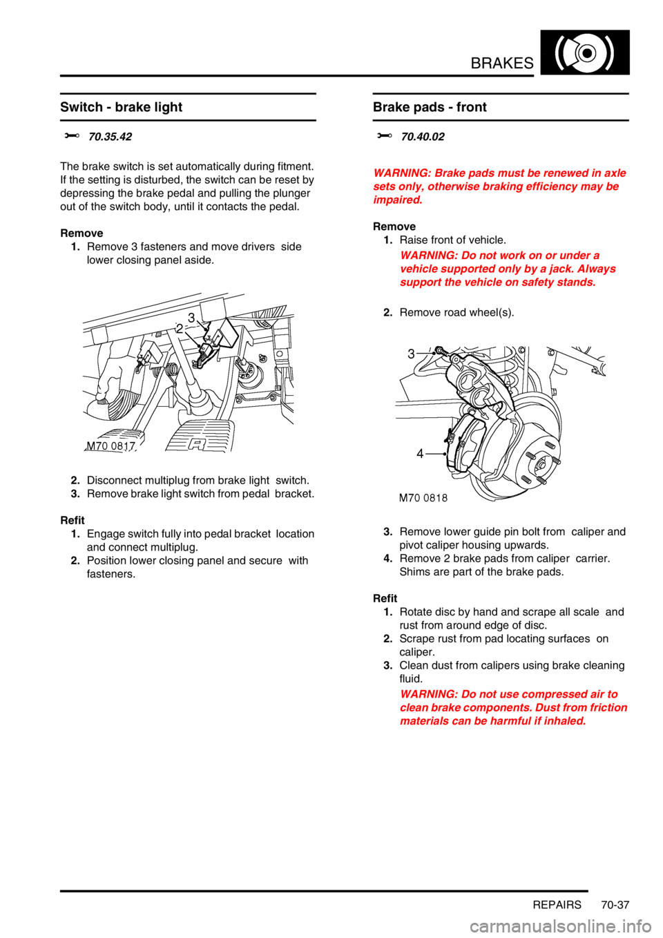
1.Remove 3 fasteners and move drivers side
lower closing panel aside.
2.Disconnect multiplug from brake light switch.
3.Remove brake light switch from pedal bracket.
Refit
1.Engage switch fully into pedal bracket location
and connect multiplug.
2.Position lower closing panel and secure with
fasteners.
Brake pads - front
$% 70.40.02
WARNING: Brake pads must be renewed in axle
sets only, otherwise braking efficiency may be
impaired.
Remove
1.Raise front of vehicle.
WARNING: Do not work on or under a
vehicle supported only by a jack. Always
support the vehicle on safety stands.
2.Remove road wheel(s).
3.Remove lower guide pin bolt from caliper and
pivot caliper housing upwards.
4.Remove 2 brake pads from caliper carrier.
Shims are part of the brake pads.
Refit
1.Rotate disc by hand and scrape all scale and
rust from around edge of disc.
2.Scrape rust from pad locating surfaces on
caliper.
3.Clean dust from calipers using brake cleaning
fluid.
WARNING: Do not use compressed air to
clean brake components. Dust from friction
materials can be harmful if inhaled.
Page 1083 of 1672

BRAKES
70-38 REPAIRS
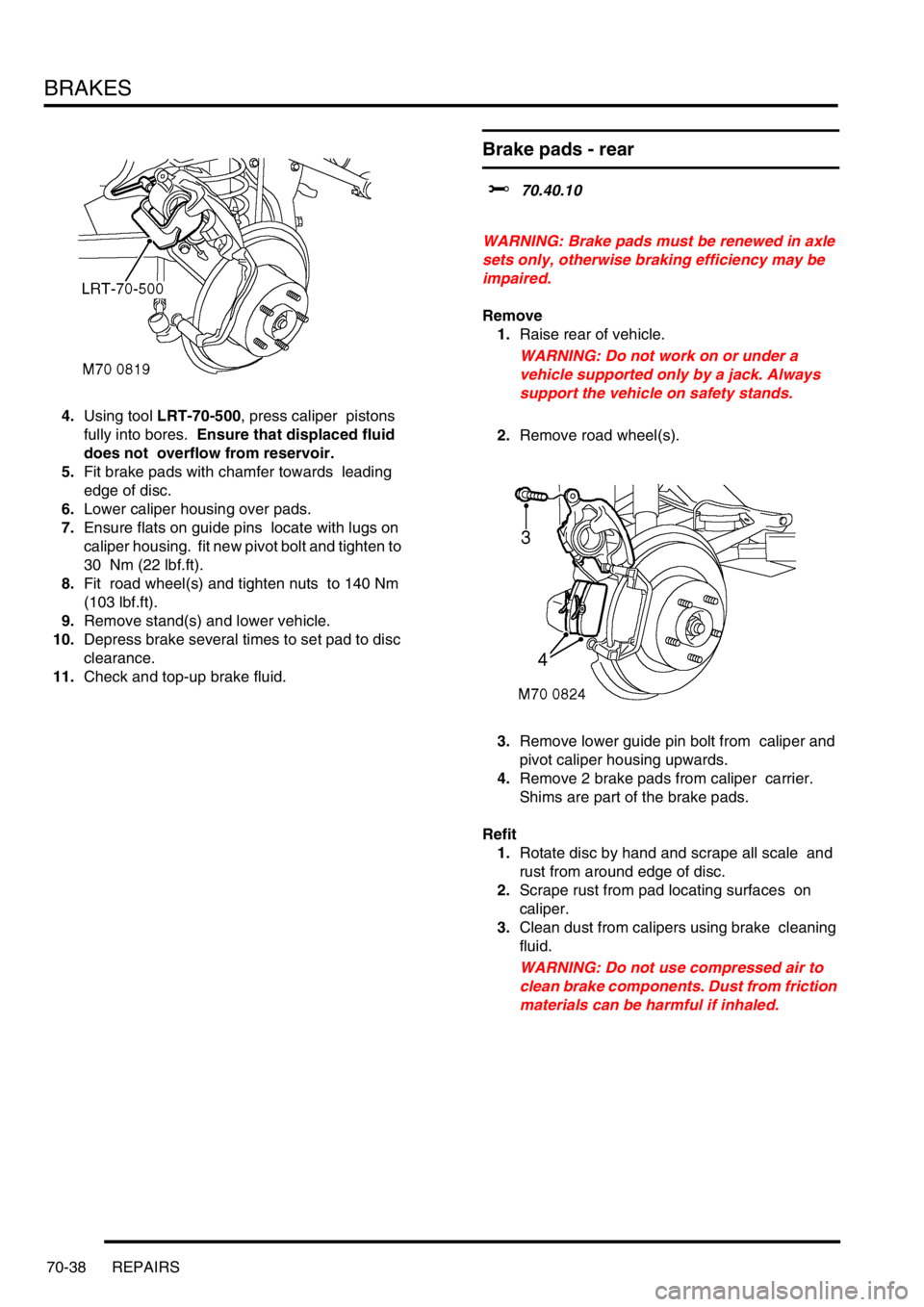
4.Using tool LRT-70-500, press caliper pistons
fully into bores. Ensure that displaced fluid
does not overflow from reservoir.
5.Fit brake pads with chamfer towards leading
edge of disc.
6.Lower caliper housing over pads.
7.Ensure flats on guide pins locate with lugs on
caliper housing. fit new pivot bolt and tighten to
30 Nm (22 lbf.ft).
8.Fit road wheel(s) and tighten nuts to 140 Nm
(103 lbf.ft).
9.Remove stand(s) and lower vehicle.
10.Depress brake several times to set pad to disc
clearance.
11.Check and top-up brake fluid.
Brake pads - rear
$% 70.40.10
WARNING: Brake pads must be renewed in axle
sets only, otherwise braking efficiency may be
impaired.
Remove
1.Raise rear of vehicle.
WARNING: Do not work on or under a
vehicle supported only by a jack. Always
support the vehicle on safety stands.
2.Remove road wheel(s).
3.Remove lower guide pin bolt from caliper and
pivot caliper housing upwards.
4.Remove 2 brake pads from caliper carrier.
Shims are part of the brake pads.
Refit
1.Rotate disc by hand and scrape all scale and
rust from around edge of disc.
2.Scrape rust from pad locating surfaces on
caliper.
3.Clean dust from calipers using brake cleaning
fluid.
WARNING: Do not use compressed air to
clean brake components. Dust from friction
materials can be harmful if inhaled.