2002 LAND ROVER DISCOVERY warning
[x] Cancel search: warningPage 1034 of 1672
REAR SUSPENSION
REPAIRS 64-29
Damper - rear
$% 64.30.02
Remove
1.Raise rear of vehicle and support under
chassis.
WARNING: Do not work on or under a
vehicle supported only by a jack. Always
support the vehicle on safety stands.
2.Remove road wheel.
3.Support weight of axle on a jack.
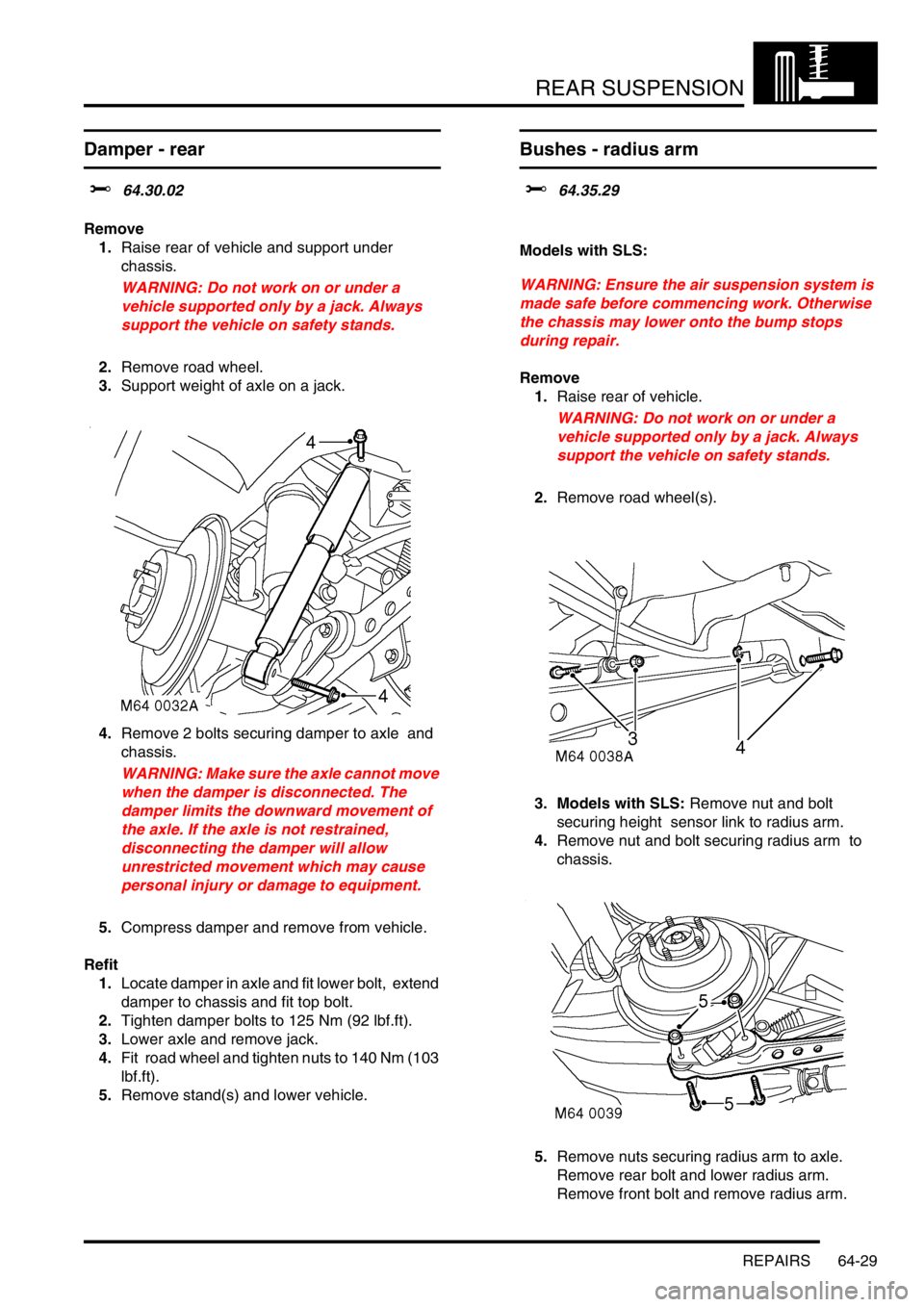
4.Remove 2 bolts securing damper to axle and
chassis.
WARNING: Make sure the axle cannot move
when the damper is disconnected. The
damper limits the downward movement of
the axle. If the axle is not restrained,
disconnecting the damper will allow
unrestricted movement which may cause
personal injury or damage to equipment.
5.Compress damper and remove from vehicle.
Refit
1.Locate damper in axle and fit lower bolt, extend
damper to chassis and fit top bolt.
2.Tighten damper bolts to 125 Nm (92 lbf.ft).
3.Lower axle and remove jack.
4.Fit road wheel and tighten nuts to 140 Nm (103
lbf.ft).
5.Remove stand(s) and lower vehicle.
Bushes - radius arm
$% 64.35.29
Models with SLS:
WARNING: Ensure the air suspension system is
made safe before commencing work. Otherwise
the chassis may lower onto the bump stops
during repair.
Remove
1.Raise rear of vehicle.
WARNING: Do not work on or under a
vehicle supported only by a jack. Always
support the vehicle on safety stands.
2.Remove road wheel(s).
3. Models with SLS: Remove nut and bolt
securing height sensor link to radius arm.
4.Remove nut and bolt securing radius arm to
chassis.
5.Remove nuts securing radius arm to axle.
Remove rear bolt and lower radius arm.
Remove front bolt and remove radius arm.
Page 1036 of 1672
REAR SUSPENSION
REPAIRS 64-31
Bushes - Watts linkage
$% 64.35.35
Models with SLS:
WARNING: Ensure the air suspension system is
made safe before commencing work. Otherwise
the chassis may lower onto the bump stops
during repair.
Remove
1.Raise rear of vehicle.
WARNING: Do not work on or under a
vehicle supported only by a jack. Always
support the vehicle on safety stands.
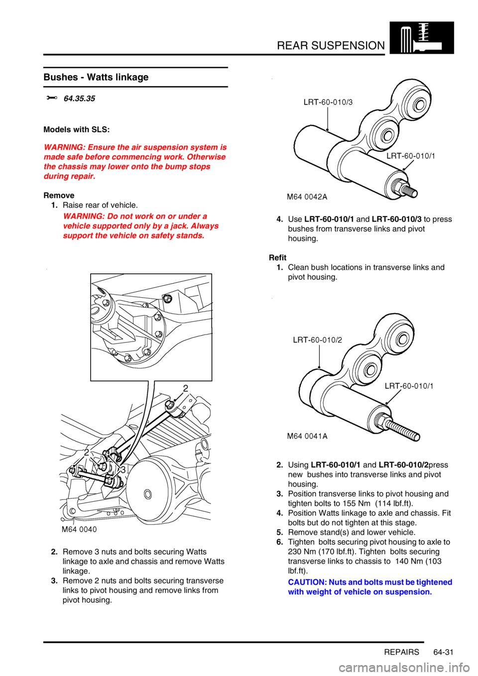
2.Remove 3 nuts and bolts securing Watts
linkage to axle and chassis and remove Watts
linkage.
3.Remove 2 nuts and bolts securing transverse
links to pivot housing and remove links from
pivot housing. 4.Use LRT-60-010/1 and LRT-60-010/3 to press
bushes from transverse links and pivot
housing.
Refit
1.Clean bush locations in transverse links and
pivot housing.
2.Using LRT-60-010/1 and LRT-60-010/2press
new bushes into transverse links and pivot
housing.
3.Position transverse links to pivot housing and
tighten bolts to 155 Nm (114 lbf.ft).
4.Position Watts linkage to axle and chassis. Fit
bolts but do not tighten at this stage.
5.Remove stand(s) and lower vehicle.
6.Tighten bolts securing pivot housing to axle to
230 Nm (170 lbf.ft). Tighten bolts securing
transverse links to chassis to 140 Nm (103
lbf.ft).
CAUTION: Nuts and bolts must be tightened
with weight of vehicle on suspension.
Page 1037 of 1672
REAR SUSPENSION
64-32 REPAIRS
Sensor - height - SLS
$% 64.36.01
WARNING: Ensure the air suspension system is
made safe before commencing work. Otherwise
the chassis may lower onto the bump stops
during repair.
Remove
1.Raise rear of vehicle.
WARNING: Do not work on or under a
vehicle supported only by a jack. Always
support the vehicle on safety stands.
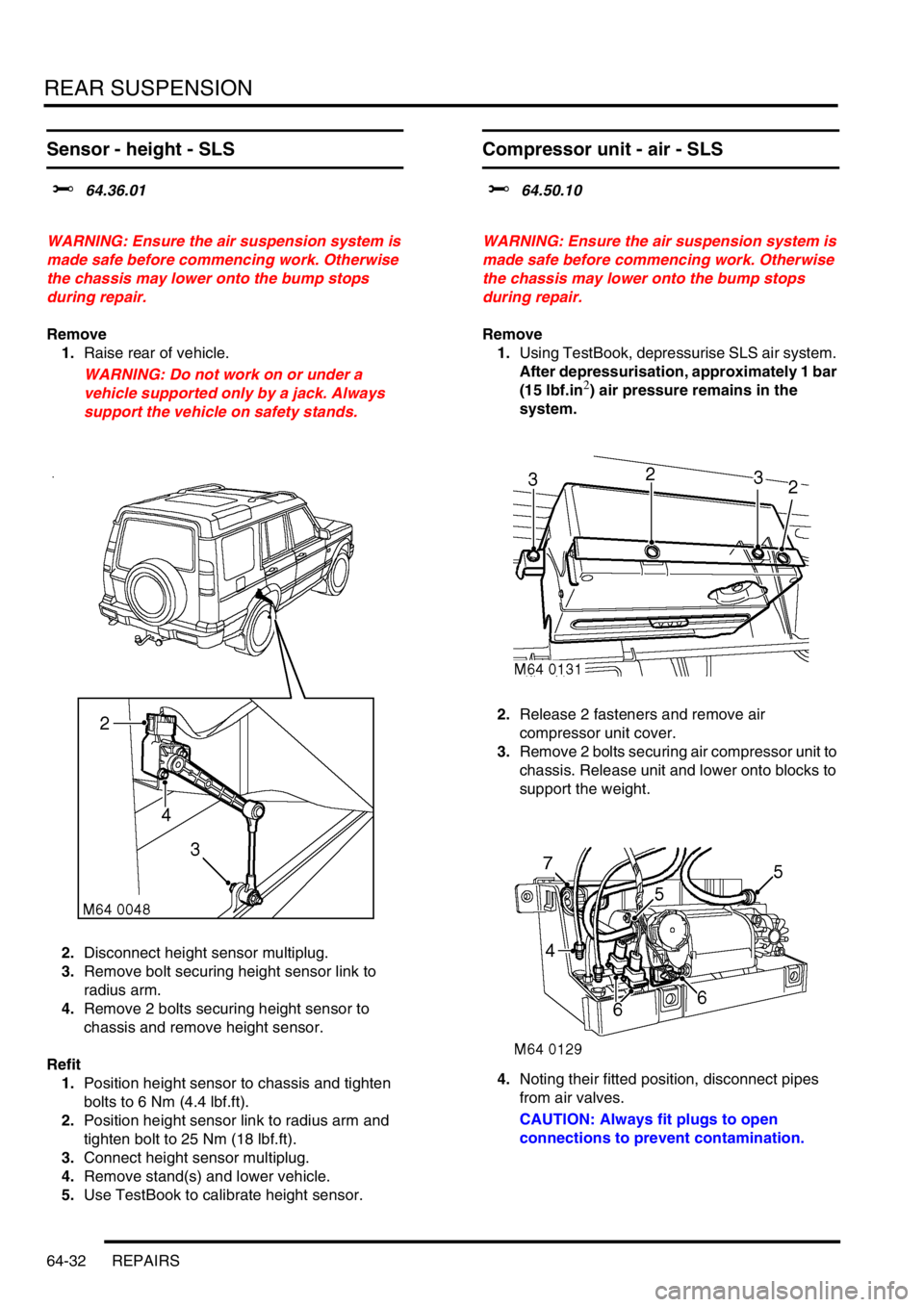
2.Disconnect height sensor multiplug.
3.Remove bolt securing height sensor link to
radius arm.
4.Remove 2 bolts securing height sensor to
chassis and remove height sensor.
Refit
1.Position height sensor to chassis and tighten
bolts to 6 Nm (4.4 lbf.ft).
2.Position height sensor link to radius arm and
tighten bolt to 25 Nm (18 lbf.ft).
3.Connect height sensor multiplug.
4.Remove stand(s) and lower vehicle.
5.Use TestBook to calibrate height sensor.
Compressor unit - air - SLS
$% 64.50.10
WARNING: Ensure the air suspension system is
made safe before commencing work. Otherwise
the chassis may lower onto the bump stops
during repair.
Remove
1.Using TestBook, depressurise SLS air system.
After depressurisation, approximately 1 bar
(15 lbf.in
2) air pressure remains in the
system.
2.Release 2 fasteners and remove air
compressor unit cover.
3.Remove 2 bolts securing air compressor unit to
chassis. Release unit and lower onto blocks to
support the weight.
4.Noting their fitted position, disconnect pipes
from air valves.
CAUTION: Always fit plugs to open
connections to prevent contamination.
Page 1040 of 1672
REAR SUSPENSION
REPAIRS 64-35
Air valve - SLS
$% 64.50.47
WARNING: Ensure the air suspension system is
made safe before commencing work. Otherwise
the chassis may lower onto the bump stops
during repair.
Remove
1.Using TestBook, depressurise SLS air system.
After depressurisation, approximately 1 bar
(15 lbf.in
2) air pressure remains in the
system.
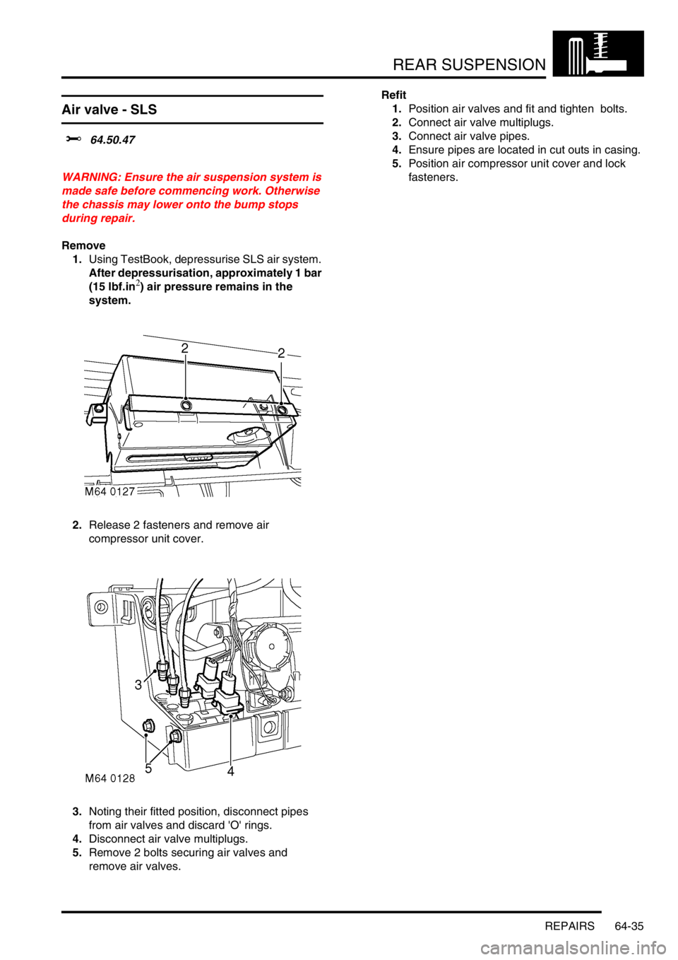
2.Release 2 fasteners and remove air
compressor unit cover.
3.Noting their fitted position, disconnect pipes
from air valves and discard 'O' rings.
4.Disconnect air valve multiplugs.
5.Remove 2 bolts securing air valves and
remove air valves. Refit
1.Position air valves and fit and tighten bolts.
2.Connect air valve multiplugs.
3.Connect air valve pipes.
4.Ensure pipes are located in cut outs in casing.
5.Position air compressor unit cover and lock
fasteners.
Page 1041 of 1672
REAR SUSPENSION
64-36 REPAIRS
Actuator - rear - ACE
$% 64.60.40
CAUTION: The ACE hydraulic system is
extremely sensitive to the ingress of dirt or
debris. The smallest amount could render the
system unserviceable. It is imperative that the
following precautions are taken.
lACE components are thoroughly cleaned
externally before work commences;
lall opened pipe and module ports are
capped immediately;
lall fluid is stored in and administered
through clean containers.
Models with SLS:
WARNING: Ensure the air suspension system is
made safe before commencing work. Otherwise
the chassis may lower onto the bump stops
during repair.
Remove
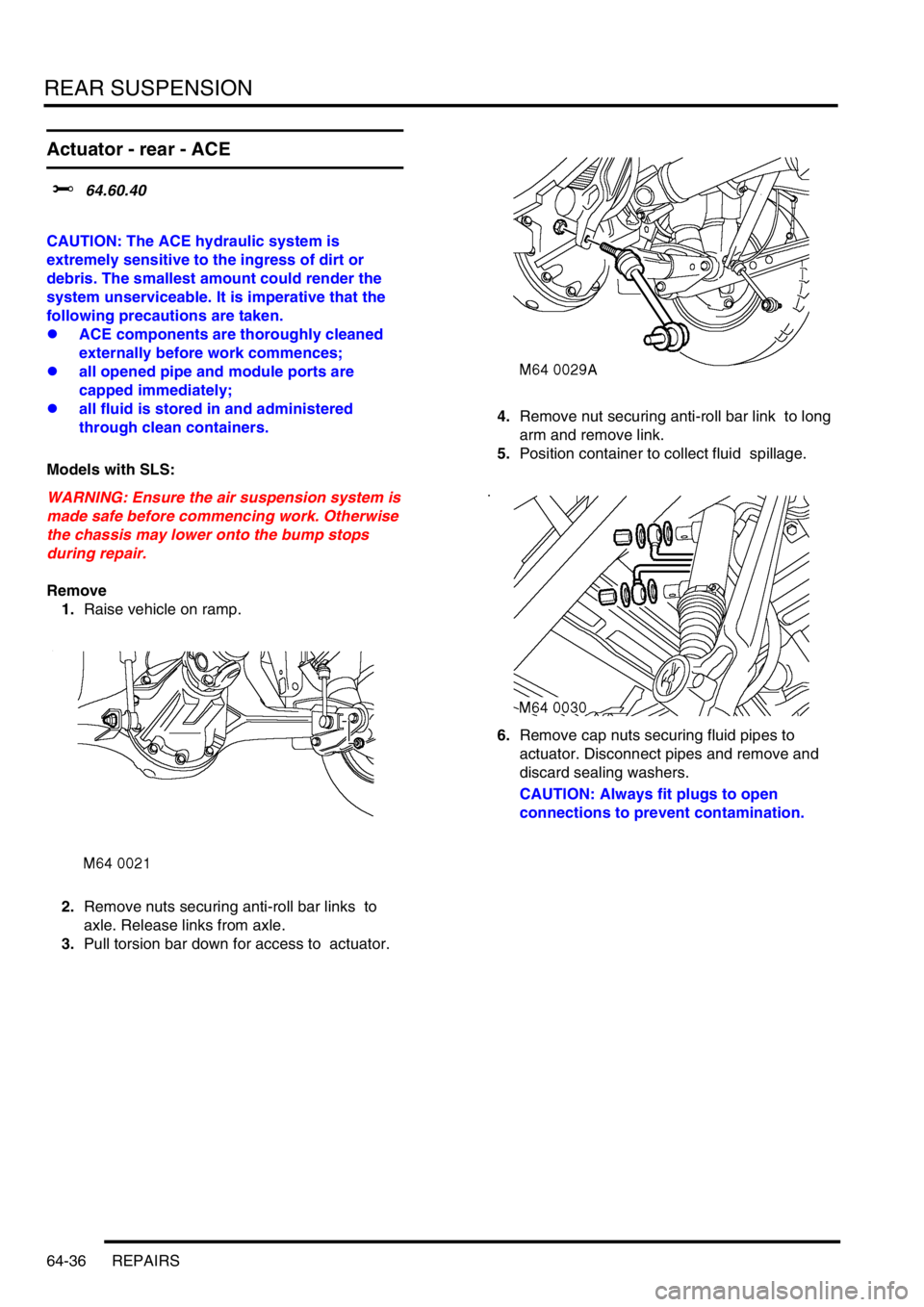
1.Raise vehicle on ramp.
2.Remove nuts securing anti-roll bar links to
axle. Release links from axle.
3.Pull torsion bar down for access to actuator. 4.Remove nut securing anti-roll bar link to long
arm and remove link.
5.Position container to collect fluid spillage.
6.Remove cap nuts securing fluid pipes to
actuator. Disconnect pipes and remove and
discard sealing washers.
CAUTION: Always fit plugs to open
connections to prevent contamination.
Page 1043 of 1672
REAR SUSPENSION
64-38 REPAIRS
Bushes - rear long arm - ACE
$% 64.60.46
CAUTION: The ACE hydraulic system is
extremely sensitive to the ingress of dirt or
debris. The smallest amount could render the
system unserviceable. It is imperative that the
following precautions are taken.
lACE components are thoroughly cleaned
externally before work commences;
lall opened pipe and module ports are
capped immediately;
lall fluid is stored in and administered
through clean containers.
Models with SLS:
WARNING: Ensure the air suspension system is
made safe before commencing work. Otherwise
the chassis may lower onto the bump stops
during repair.
Remove
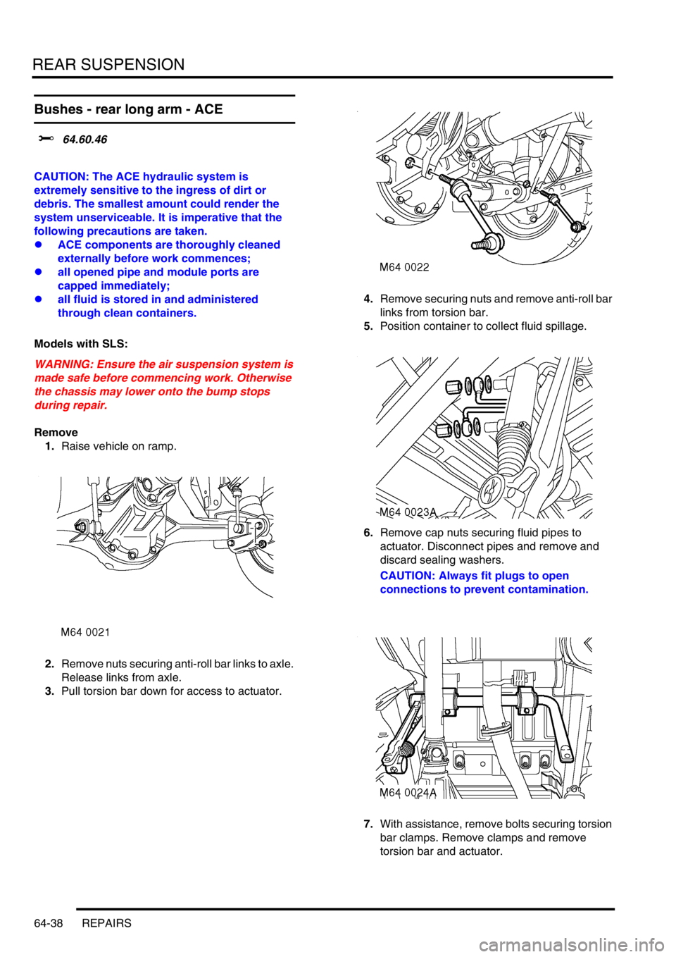
1.Raise vehicle on ramp.
2.Remove nuts securing anti-roll bar links to axle.
Release links from axle.
3.Pull torsion bar down for access to actuator.4.Remove securing nuts and remove anti-roll bar
links from torsion bar.
5.Position container to collect fluid spillage.
6.Remove cap nuts securing fluid pipes to
actuator. Disconnect pipes and remove and
discard sealing washers.
CAUTION: Always fit plugs to open
connections to prevent contamination.
7.With assistance, remove bolts securing torsion
bar clamps. Remove clamps and remove
torsion bar and actuator.
Page 1051 of 1672

BRAKES
70-6 DESCRIPTION AND OPERATION
For all control functions, the ABS modulator regulates the hydraulic pressure to the brakes to control the speed of all
four wheels, either individually or in axle pairs. Operation of the ABS modulator is controlled by the Self Levelling and
Anti-lock Braking Systems (SLABS) ECU. The SLABS ECU also operates warning indications in the instrument pack
to provide the driver with status information on each function.
Brake servo assembly
The brake servo assembly provides power assistance to reduce the pedal load when braking. If the brake servo
assembly fails, the hydraulic system still functions but will require greater brake pedal effort due to the lack of vacuum
assistance.
Two integral tie bolts attach the brake servo assembly to the pedal and bracket assembly on the engine bulkhead.
The master cylinder assembly is attached to the forward ends of the tie bolts.
The brake servo assembly consists of a circular housing which contains two diaphragms, a central plate, a control
valve assembly, input and output push rods and a filter. The input push rod is connected to the brake pedal. The output
push rod locates in the primary piston of the master cylinder. A protective gaiter is installed on the control valve
assembly where it extends from the rear of the housing. A non return valve, installed in a port in the front face of the
housing, is connected to a vacuum line from the engine.
The control valve assembly consists of a valve body containing a valve, a piston, a valve spring and an input rod
spring. The valve controls a vacuum port in the valve body. The piston controls an air inlet port between the valve and
the piston. A reaction disc and a ratio disc separate the piston from the output push rod. A guide tube on the front of
the valve body is attached to the front diaphragm and supported in a bush in the central plate. A return spring locates
in the open end of the guide tube.
The two diaphragms and the central plate separate the interior of the housing into four sealed chambers. The
chambers at the front of the diaphragms are connected together through fixed passages in the valve assembly. The
chambers at the rear of the diaphragms are connected together through the interior of minor diaphragms on the tie
bolts.
Brakes off
With the brake pedal released, the piston in the control valve assembly positions the valve so that the vacuum port is
open and the two pairs of chambers are connected together. When the engine is running air is evacuated through the
vacuum line and non return valve, creating a partial vacuum in all four chambers. When the engine stops, the non
return valve closes to maintain the partial vacuum and, on V8 models, prevent fuel vapour entering the brake servo.
Page 1056 of 1672
BRAKES
DESCRIPTION AND OPERATION 70-11
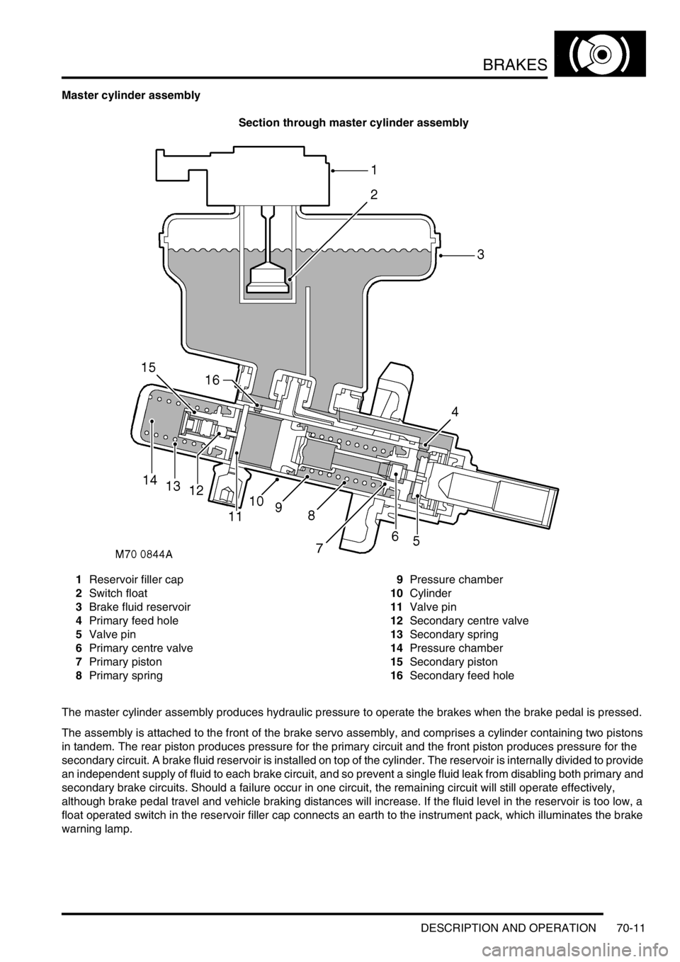
Master cylinder assembly
Section through master cylinder assembly
1Reservoir filler cap
2Switch float
3Brake fluid reservoir
4Primary feed hole
5Valve pin
6Primary centre valve
7Primary piston
8Primary spring9Pressure chamber
10Cylinder
11Valve pin
12Secondary centre valve
13Secondary spring
14Pressure chamber
15Secondary piston
16Secondary feed hole
The master cylinder assembly produces hydraulic pressure to operate the brakes when the brake pedal is pressed.
The assembly is attached to the front of the brake servo assembly, and comprises a cylinder containing two pistons
in tandem. The rear piston produces pressure for the primary circuit and the front piston produces pressure for the
secondary circuit. A brake fluid reservoir is installed on top of the cylinder. The reservoir is internally divided to provide
an independent supply of fluid to each brake circuit, and so prevent a single fluid leak from disabling both primary and
secondary brake circuits. Should a failure occur in one circuit, the remaining circuit will still operate effectively,
although brake pedal travel and vehicle braking distances will increase. If the fluid level in the reservoir is too low, a
float operated switch in the reservoir filler cap connects an earth to the instrument pack, which illuminates the brake
warning lamp.