2002 LAND ROVER DISCOVERY warning
[x] Cancel search: warningPage 1062 of 1672

BRAKES
DESCRIPTION AND OPERATION 70-17
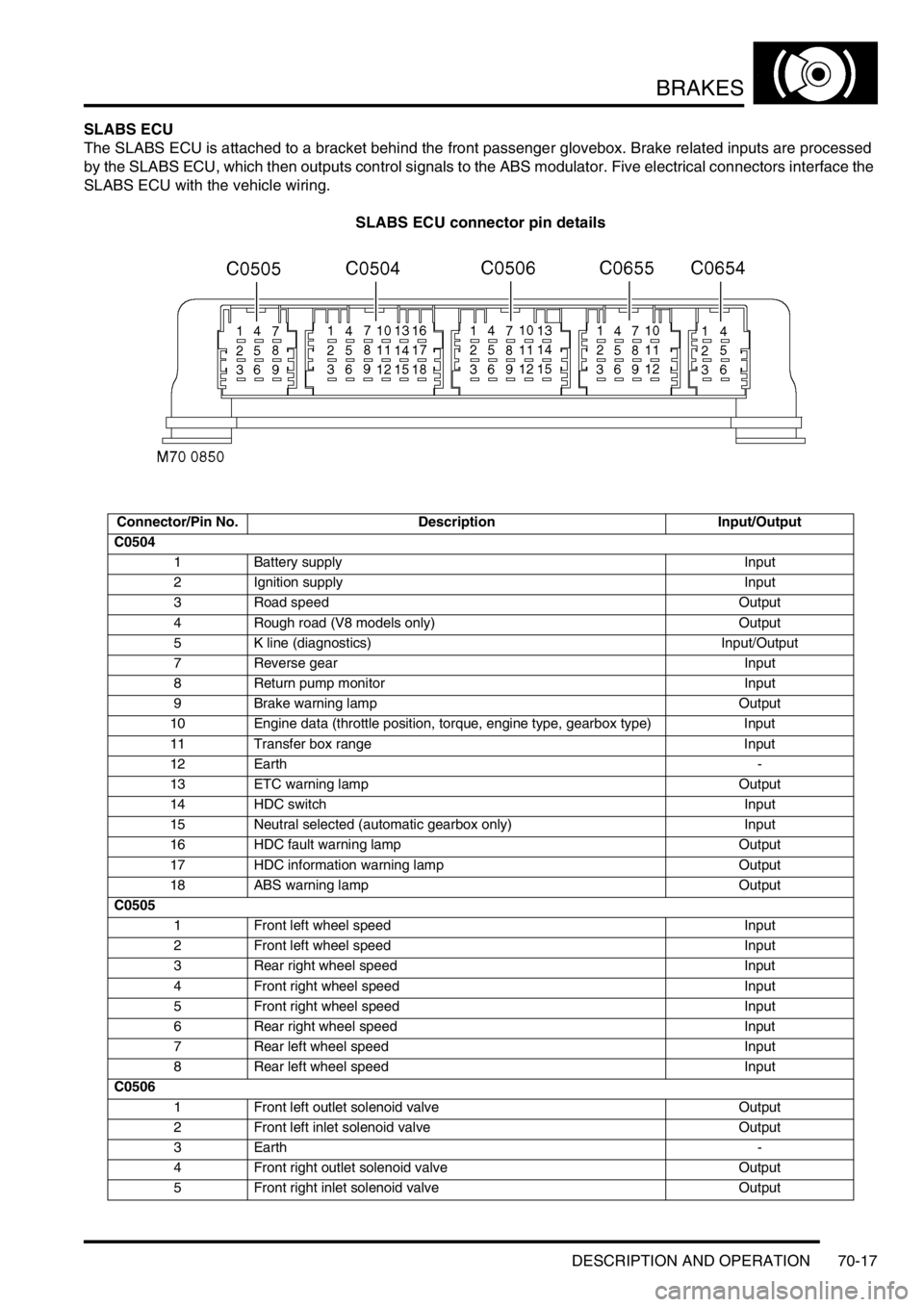
SLABS ECU
The SLABS ECU is attached to a bracket behind the front passenger glovebox. Brake related inputs are processed
by the SLABS ECU, which then outputs control signals to the ABS modulator. Five electrical connectors interface the
SLABS ECU with the vehicle wiring.
SLABS ECU connector pin details
Connector/Pin No. Description Input/Output
C0504
1 Battery supply Input
2 Ignition supply Input
3 Road speed Output
4 Rough road (V8 models only) Output
5 K line (diagnostics) Input/Output
7 Reverse gear Input
8 Return pump monitor Input
9 Brake warning lamp Output
10 Engine data (throttle position, torque, engine type, gearbox type) Input
11 Transfer box range Input
12 Earth-
13 ETC warning lamp Output
14 HDC switch Input
15 Neutral selected (automatic gearbox only) Input
16 HDC fault warning lamp Output
17 HDC information warning lamp Output
18 ABS warning lamp Output
C0505
1 Front left wheel speed Input
2 Front left wheel speed Input
3 Rear right wheel speed Input
4 Front right wheel speed Input
5 Front right wheel speed Input
6 Rear right wheel speed Input
7 Rear left wheel speed Input
8 Rear left wheel speed Input
C0506
1 Front left outlet solenoid valve Output
2 Front left inlet solenoid valve Output
3Earth-
4 Front right outlet solenoid valve Output
5 Front right inlet solenoid valve Output
Page 1063 of 1672

BRAKES
70-18 DESCRIPTION AND OPERATION
The SLABS ECU continually calculates vehicle speed using the wheel speed inputs from all four ABS sensors. The
calculated vehicle speed is then used as a reference against which individual wheel speeds are monitored for
unacceptable acceleration or deceleration. The ABS sensor inputs are also used by the SLABS ECU to detect vehicle
deceleration rate, vehicle cornering rate and rough terrain.
The engaged forward gear and (on manual gearbox models) the clutch status are computed from the engine data
input, the engine speed input and vehicle speed. Reverse gear status is provided by an input from the reverse lamp
switch (manual gearbox models) or the BCU (automatic gearbox models). On automatic models, the BCU also
provides the neutral selected input.
In addition to controlling the brake related functions, the SLABS ECU:
lControls the operation of the self levelling suspension (SLS) system (where fitted).
+ REAR SUSPENSION, DESCRIPTION AND OPERATION, Description.
lOn V8 models, outputs a rough road signal to the ECM when traversing rough terrain.
lOutputs a vehicle speed signal.
The vehicle speed signal is output to the following systems (where fitted):
lActive Cornering Enhancement.
+ FRONT SUSPENSION, DESCRIPTION AND OPERATION, Description - ACE.
lAir conditioning.
+ AIR CONDITIONING, DESCRIPTION AND OPERATION, Description.
lCruise control.
+ ENGINE MANAGEMENT SYSTEM - Td5, DESCRIPTION AND OPERATION, Description.
+ ENGINE MANAGEMENT SYSTEM - V8, DESCRIPTION AND OPERATION, Description - engine
management.
lEngine management.
+ ENGINE MANAGEMENT SYSTEM - Td5, DESCRIPTION AND OPERATION, Description.
+ ENGINE MANAGEMENT SYSTEM - V8, DESCRIPTION AND OPERATION, Description - engine
management.
lIn-car entertainment.
+ IN CAR ENTERTAINMENT, DESCRIPTION AND OPERATION, Description.
lInstrument pack.
+ INSTRUMENTS, DESCRIPTION AND OPERATION, Description.
ABS sensors
The ABS sensors supply the SLABS ECU with a sinusoidal speed signal from each wheel. An inductive sensor,
installed in the hub bearing of each wheel, senses off a 60 tooth exciter ring integrated into the inner race of the hub
bearing. Each ABS sensor has a fly-lead connecting it to the vehicle wiring.
6 Shuttle valve switches Input
7 Rear left outlet solenoid valve Output
8 Rear left inlet solenoid valve Output
9 Centre differential lock switch Input
10 Rear right outlet solenoid valve Output
11 Rear right inlet solenoid valve Output
12 Brake lamp relay Output
15 Return pump relay Output
C0655
7 Audible warning Output
10 Engine speed Input
Connector and pins not listed are either not used or used by the self levelling suspension system.
+ REAR SUSPENSION, DESCRIPTION AND OPERATION, Description.
Connector/Pin No. Description Input/Output
Page 1064 of 1672

BRAKES
DESCRIPTION AND OPERATION 70-19
HDC switch
The HDC switch is a latching push switch installed on the fascia, in the switchpack inboard of the steering wheel.
When pushed in, the switch connects an ignition supply to the SLABS ECU to initiate HDC.
Warning indications
The SLABS ECU operates audible and visual warnings to convey brake system status.
Audible warning
A repetitive chime, at a frequency of 2 Hz, draws attention to warning lamp indications. The chime is produced on the
speaker in the instrument pack.
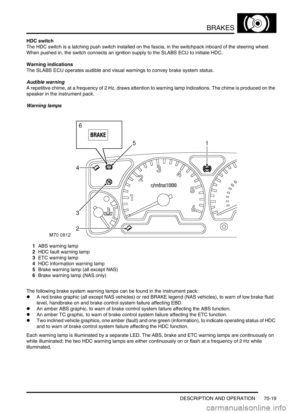
Warning lamps
1ABS warning lamp
2HDC fault warning lamp
3ETC warning lamp
4HDC information warning lamp
5Brake warning lamp (all except NAS)
6Brake warning lamp (NAS only)
The following brake system warning lamps can be found in the instrument pack:
lA red brake graphic (all except NAS vehicles) or red BRAKE legend (NAS vehicles), to warn of low brake fluid
level, handbrake on and brake control system failure affecting EBD.
lAn amber ABS graphic, to warn of brake control system failure affecting the ABS function.
lAn amber TC graphic, to warn of brake control system failure affecting the ETC function.
lTwo inclined vehicle graphics, one amber (fault) and one green (information), to indicate operating status of HDC
and to warn of brake control system failure affecting the HDC function.
Each warning lamp is illuminated by a separate LED. The ABS, brake and ETC warning lamps are continuously on
while illuminated; the two HDC warning lamps are either continuously on or flash at a frequency of 2 Hz while
illuminated.
Page 1065 of 1672

BRAKES
70-20 DESCRIPTION AND OPERATION
Operation
Refer to illustration.
+ BRAKES, DESCRIPTION AND OPERATION, Brake system control diagram.
When the ignition is switched on, the SLABS ECU performs a check of the brake related warning lamps as part of the
power up procedure. The warning lamps are illuminated for approximately 3 seconds and then extinguished. If a fault
warning lamp remains illuminated after the lamp check, a fault has been detected and repair action is required.
ABS
The ABS function prevents the road wheels locking during brake application, thus maintaining vehicle stability even
under emergency conditions.
WARNING: ABS is an aid to retaining steering control and stability while braking:
lABS cannot defy the natural laws of physics acting on the vehicle.
lABS will not prevent accidents resulting from excessive cornering speeds, following another vehicle too
closely, aquaplaning, etc.
lThe additional control provided by ABS must never be exploited in a dangerous or reckless manner
which could jeopardise the safety of driver or other road users.
lThe fitting of ABS does not imply that the vehicle will always stop in a shorter distance.
NOTE: During normal braking the feel of the brake pedal on vehicles equipped with ABS will be the same as that on
non ABS vehicles. During anti-lock braking operation the driver will experience feedback in the form of a pulsating
brake pedal and solenoid/pump motor noise from the ABS modulator.
The anti-lock braking function is automatically enabled whenever the ABS modulator is in the normal braking mode.
While the anti-lock braking function is enabled, if the SLABS ECU detects a wheel decelerating faster than the
average and at the calibrated wheel slip limit for ABS operation, it operates the ABS modulator in the ABS braking
mode for the affected wheel.
EBD
The EBD function optimises the distribution of hydraulic pressure between the front and rear axles, under all vehicle
load configurations and road conditions, to maintain vehicle stability during braking. EBD operates in forward and
reverse and is automatically enabled whenever the ABS modulator is in the normal braking mode at vehicle
deceleration rates of 0.3 g and above (i.e. medium to high brake pedal loads). EBD operation is similar to that of ABS,
but is calibrated to intervene at lower wheel slip limits and operates the brakes in axle pairs instead of individually.
During braking, if the SLABS ECU detects the wheels of one axle going slower than those of the other axle, i.e. a
potential wheel slip situation, it signals the ABS modulator to close the inlet solenoid valve for the brakes of the slower
wheels. This prevents any further increase in hydraulic pressure to those brakes, while allowing the hydraulic pressure
to the brakes on the other axle to increase and so maximise the overall braking effort. If the wheel speeds of the axle
being subjected to EBD control return within the calibrated wheel slip limits, the SLABS ECU signals a stepped
opening of the inlet solenoid valves, which allows a progressive increase of hydraulic pressure to the related brakes.
Operation of EBD is detectable from a stiffening of brake pedal movement as the inlet solenoid valves close and a
slight pulsing of the brake pedal as the inlet solenoid valves open. EBD operation ceases immediately the brake pedal
is released.
The wheel slip limit for EBD operation varies with vehicle speed. During normal operation, the inlet solenoid valves
always operate in axle pairs, with only one axle pair closed at any one time. Since the most lightly loaded wheel during
a braking manoeuvre will usually be the first to reach the slip limit, under most vehicle load configurations and road
conditions EBD control occurs on the trailing axle. However, EBD control can occur on the leading axle or switch
between axles during the braking manoeuvre.
Page 1066 of 1672

BRAKES
DESCRIPTION AND OPERATION 70-21
ETC
The ETC function uses brake intervention to prevent wheel spin and maintain even torque distribution to the wheels.
ETC is automatically enabled while the brakes are off at speeds up to 62.5 mph (100 km/h), and operates the brakes
either individually or in axle pairs:
lAt speeds up to 31.3 mph (50 km/h), ETC uses individual brake intervention to maintain even torque distribution
between wheels on the same axle.
lVehicles up to 03 model year – At speeds between 0 and 62.5 mph (0 and 100 km/h), ETC also uses brake
intervention in axle pairs to maintain even torque distribution between the front and rear axles. In effect, this mode
of operation replaces the centre differential lock of the transfer box which, although still incorporated, is non
operational under normal driving conditions.
+ TRANSFER BOX - LT230SE, DESCRIPTION AND OPERATION, Description. If the centre differential
lock is in the locked condition, the SLABS ECU illuminates the ABS and ETC warning lamps and inhibits the ETC
function (the ABS, EBD and HDC functions are retained, but at degraded performance levels).
lVehicles from 03 model year (with differential lock fitted) – At speeds between 0 and 62.5 mph (0 and 100
km/h), ETC uses brake intervention in axle pairs to maintain even torque distribution between the front and rear
axles. If the centre differential lock is in the locked condition, the differential lock warning lamp in the instrument
pack is illuminated. The ABS, EBD, ETC and HDC functions are retained, but with revised parameters to suit the
locked differential.
While the ETC function is enabled, if the SLABS ECU detects a wheel accelerating faster than the average, indicating
loss of traction, it operates the ABS modulator in the active braking mode. Depending on the vehicle speed, active
braking is employed for either the brake of the affected wheel or for both brakes on the affected axle, until all four
wheels are driven at approximately the same speed again. During active braking the SLABS ECU also illuminates the
ETC warning lamp, for a minimum of 2 seconds or for the duration that ETC is active. ETC operation is desensitised
during 'hard' cornering.
HDC
HDC uses brake intervention to provide a controlled descent ability in off road conditions when engine braking is
insufficient to maintain a comfortable speed. This allows the driver to leave HDC selected and to control the vehicle's
descent speed, down to the system's minimum target speed, using only the accelerator pedal. The HDC function is
selected on/off by a switch on the fascia. When selected on, HDC is enabled in all forward gears and reverse provided:
lVehicle speed is below 31.3 mph (50 km/h).
lThe transfer box is in low range.
lOn manual gearbox vehicles, the clutch is engaged.
When HDC is enabled, the HDC information warning lamp illuminates. If HDC is selected outside the above
conditions, the HDC information warning lamp flashes and the audible warning sounds continuously.
When HDC is enabled, the SLABS ECU calculates a target speed from the throttle position element of the engine data
input, and compares this with actual speed. If the actual speed is higher than the target speed, the SLABS ECU
operates the ABS modulator in the active braking mode to slow the vehicle down to the target speed. While the braking
force is being applied, the SLABS ECU also energizes the brake lamp relay to put the brake lamps on. Active braking
is discontinued while vehicle speed is below the target speed or if the foot brakes are applied. Applying the foot brakes
during active braking may result in a pulse through the brake pedal, which is normal.
During active braking, the brakes are operated predominantly on the wheels of the leading axle, but if that is not
sufficient to achieve the required deceleration the brakes of the trailing axle are also applied. The deceleration rate is
dependent on the speed differential between initial vehicle speed and the target speed. The deceleration rates are
relatively low at higher speed differentials, then progressively increase as vehicle speed approaches the target speed.
Anti-lock braking is also enabled during active braking, but at very low speeds some wheel lock can occur.
The target speed increases as the accelerator pedal is pressed, from a programmed minimum with the accelerator
pedal released, up to a maximum of 31.3 mph (50 km/h). For any given accelerator pedal position, while travelling
uphill or on level ground the target speed is always greater than the corresponding vehicle speed, which allows the
vehicle to be driven normally without HDC intervention. However, when travelling downhill, the gravitational effect on
the vehicle means that for any given accelerator pedal position the target speed is less than the corresponding vehicle
speed, and HDC intervenes to limit vehicle speed to the target speed.
Page 1067 of 1672

BRAKES
70-22 DESCRIPTION AND OPERATION
Minimum target speed
The minimum target speed depends on which gear is engaged. Reduced minimum target speeds are employed for
some gears if rough terrain or sharp bends are encountered while already travelling at the normal minimum target
speed. If loss of traction makes it impossible to maintain the minimum target speed, the SLABS ECU temporarily
increases the minimum target speed to maintain stability, then restores the normal minimum target speed when
traction improves.
HDC minimum target speeds
Fade out
To provide a safe transition from active braking to brakes off, the SLABS ECU invokes a fade out strategy if it detects
any of the following during active braking:
lA system fault.
lThe conditions for HDC are no longer being met.
lPossible brake overheat.
The fade out strategy increases the target speed at a low constant acceleration rate, independent of actual throttle
position. This results in the braking effort being gradually reduced and then discontinued. The SLABS ECU operates
warning indications during fade out that are dependent on the cause.
Fade out warning indications
Clutch disengagement/neutral selection
During active braking, if the SLABS ECU detects the clutch is disengaged or neutral is selected, it flashes the HDC
information warning lamp and sounds the audible warning continuously to indicate that conditions for HDC are no
longer being met. Initially, the SLABS ECU also fixes the target speed to the applicable minimum target speed, but if
the condition continues for approximately 60 seconds the SLABS ECU invokes fade out.
Brake overheat prevention
To prevent the brakes overheating, the SLABS ECU monitors the amount of active braking employed and, from this,
estimates brake temperature. If the SLABS ECU estimates the brake temperature has exceeded a preset limit, it
flashes the HDC fault warning lamp and sounds the audible warning continuously, to indicate that HDC should be
deselected to allow the brakes to cool. If active braking continues and the SLABS ECU estimates that brake
temperature has increased to an unacceptable level, fade out is employed and HDC is disabled. After fade out, the
audible warning is discontinued but the HDC fault warning lamp continues to flash, while HDC is selected, until the
SLABS ECU estimates brake temperature to be at an acceptable level. This calculation continues even if the ignition
is turned off, so turning the ignition off and back on will not reduce the disabled time. When the SLABS ECU estimates
the brake temperature to be acceptable, it extinguishes the HDC fault warning lamp and illuminates the HDC
information warning lamp to indicate that HDC is re-enabled. The disabled time is dependent on vehicle speed; typical
times at constant vehicle speeds are as follows:
Gear Speed, mph (km/h)
Manual gearbox Automatic gearbox
Normal Reduced Normal Reduced
1 4.4 (7.0) 4.4 (7.0) 4.4 (7.0) 4.4 (7.0)
2 5.2 (8.3) 4.4 (7.0) 4.4 (7.0) 4.4 (7.0)
3 6.0 (9.6) 4.4 (7.0) 7.5 (12.0) 6.0 (9.6)
4 7.5 (12.0) 6.0 (9.6) 7.5 (12.0) 6.0 (9.6)
5 8.8 (14.0) 7.0 (11.2) - -
Reverse 3.5 (5.6) 3.5 (5.6) 3.5 (5.6) 3.5 (5.6)
Neutral or clutch
disengaged8.8 (14.0) Last off road speed 4.4 (7.0) 4.4 (7.0)
Cause Warning indication
HDC fault warning lamp HDC information
warning lampAudible warning
Fault detected On Flashes Continuous
HDC conditions not met Off Flashes Continuous
Brake overheat prevention Flashes Off Continuous
Page 1068 of 1672

BRAKES
DESCRIPTION AND OPERATION 70-23
Typical disabled times
Diagnostics
While the ignition is on, the diagnostics function of the SLABS ECU monitors the system for faults. In addition, the
return pump is tested by pulsing it briefly immediately after the engine starts provided vehicle speed exceeded 4.4
mph (7 km/h) during the previous ignition cycle. If a fault exists in a warning lamp circuit, the lamp will not illuminate
during the lamp check at ignition on but, provided there are no other faults, the related function will otherwise be fully
operational. If a fault is detected during the power up, the SLABS ECU stores a related fault code in memory and
illuminates the appropriate fault warning lamps. If a fault is detected later in the drive cycle, the SLABS ECU also
sounds the audible warning three times.
Fault codes and diagnostic routines can be accessed by connecting Testbook to the vehicle's diagnostic connector
in the driver's footwell.
Warning lamp fault operation
After detecting a fault, the SLABS ECU selects an appropriate default strategy which, where possible, retains some
operational capability. A shuttle valve switch fault and throttle position signal fault are classified as permanent faults.
If a permanent fault is detected, the related warning lamp illumination and default strategies are automatically
employed in subsequent ignition cycles, even if the fault is intermittent, until the fault has been rectified and cleared
from memory. If a non permanent fault is detected, the related warning lamp illumination and default strategies will
only be employed in subsequent ignition cycles if the fault is still present.
After rectification of an ABS sensor fault, the ABS and ETC functions are disabled, and the ABS warning lamp remains
illuminated after the lamp check, until vehicle speed exceeds 9.4 mph (15 km/h) (to allow additional checks to be
performed).
Vehicle speed, mph (km/h) Time, minutes
1.3 (2) 40
12.5 (20) 33
15.6 (25) 17
25.0 (40) 9
31.3 (50) 6
Item Check Warning lamp
ABS Brake ETC HDC
fault
ABS sensors Resistance (to check status) On On On On
Brake lamps relay Open/Short circuit Off Off Off On
Engine data Sticking throttle, signal failure, data corruption Off Off On On
Inlet solenoid valves Open/Short circuit On On On On
Outlet solenoid valves Open/Short circuit On On On On
Reference earth Connection to earth On On On On
Return pump monitor Correct pump operation On On On On
Return pump relay Open/Short circuit On On On On
Shuttle valve switches Open/Short circuit On On On On
SLABS ECU Internal failure On On On On
Supply voltages Range (10 to 16 V) On On On On
Page 1070 of 1672

BRAKES
DESCRIPTION AND OPERATION 70-25
DESCRIPTION AND OPERAT ION
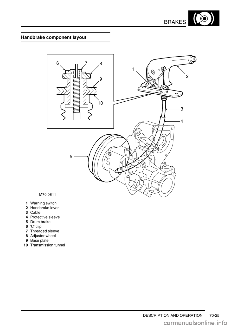
Handbrake component layout
1Warning switch
2Handbrake lever
3Cable
4Protective sleeve
5Drum brake
6'C' clip
7Threaded sleeve
8Adjuster wheel
9Base plate
10Transmission tunnel