2002 LAND ROVER DISCOVERY belt
[x] Cancel search: beltPage 1378 of 1672
AIR CONDITIONING
DESCRIPTION AND OPERATION 82-5
To accomplish the transfer of heat, the refrigerant is circulated around the system, where it passes through two
pressure/temperature regimes. In each of the pressure/temperature regimes, the refrigerant changes state, during
which process maximum heat absorption or release occurs. The low pressure/temperature regime is from the
thermostatic expansion valve, through the evaporator to the compressor; the refrigerant decreases in pressure and
temperature at the thermostatic expansion valve, then changes state from liquid to vapour in the evaporator, to absorb
heat. The high pressure/temperature regime is from the compressor, through the condenser and receiver drier to the
thermostatic expansion valve; the refrigerant increases in pressure and temperature as it passes through the
compressor, then releases heat and changes state from vapour to liquid in the condenser.
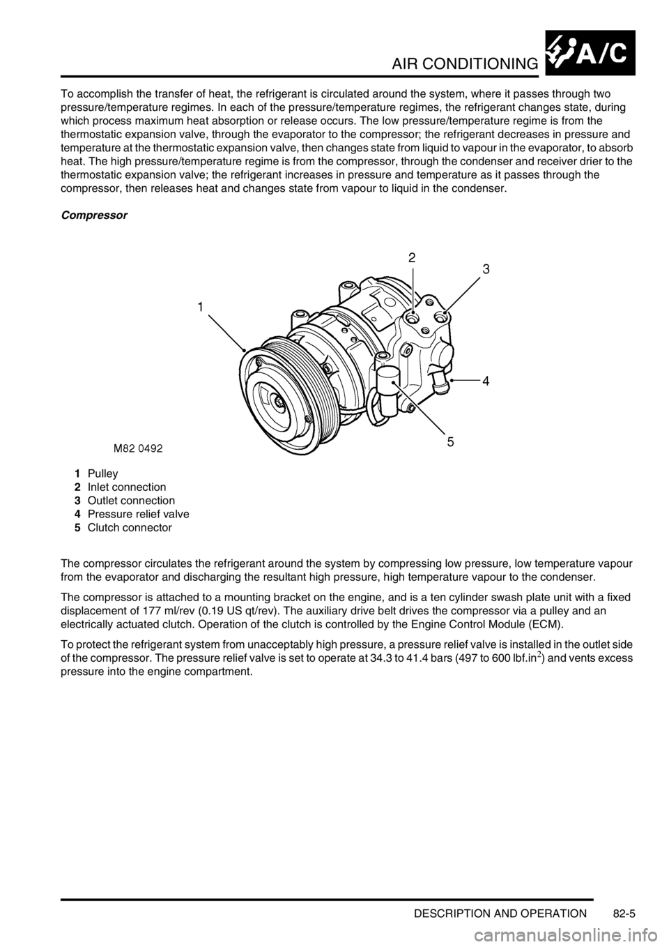
Compressor
1Pulley
2Inlet connection
3Outlet connection
4Pressure relief valve
5Clutch connector
The compressor circulates the refrigerant around the system by compressing low pressure, low temperature vapour
from the evaporator and discharging the resultant high pressure, high temperature vapour to the condenser.
The compressor is attached to a mounting bracket on the engine, and is a ten cylinder swash plate unit with a fixed
displacement of 177 ml/rev (0.19 US qt/rev). The auxiliary drive belt drives the compressor via a pulley and an
electrically actuated clutch. Operation of the clutch is controlled by the Engine Control Module (ECM).
To protect the refrigerant system from unacceptably high pressure, a pressure relief valve is installed in the outlet side
of the compressor. The pressure relief valve is set to operate at 34.3 to 41.4 bars (497 to 600 lbf.in
2) and vents excess
pressure into the engine compartment.
Page 1404 of 1672
AIR CONDITIONING
REPAIRS 82-31
REPAIRS
Compressor - diesel
$% 82.10.20
Remove
1.Remove engine acoustic cover.
2.Depressurise air conditioning system.
+ AIR CONDITIONING, REFRIGERANT
RECOVERY, RECYCLING AND
RECHARGING, Refrigerant recovery,
recycling and recharging.
3.Remove auxiliary drive belt.
+ CHARGING AND STARTING,
REPAIRS, Belt - auxiliary drive.
4.Drain cooling system.
+ COOLING SYSTEM - Td5,
ADJUSTMENTS, Drain and refill.
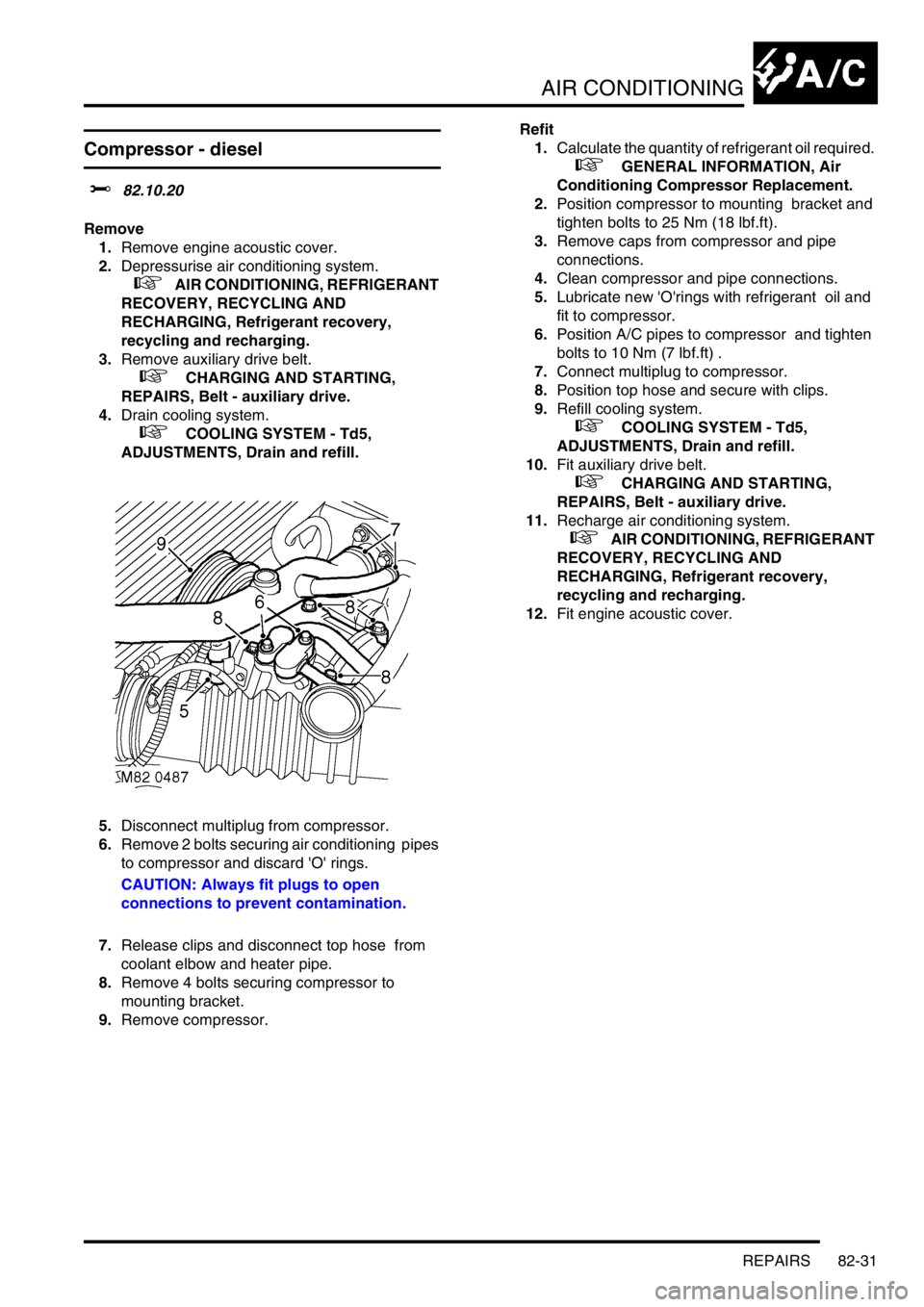
5.Disconnect multiplug from compressor.
6.Remove 2 bolts securing air conditioning pipes
to compressor and discard 'O' rings.
CAUTION: Always fit plugs to open
connections to prevent contamination.
7.Release clips and disconnect top hose from
coolant elbow and heater pipe.
8.Remove 4 bolts securing compressor to
mounting bracket.
9.Remove compressor.Refit
1.Calculate the quantity of refrigerant oil required.
+ GENERAL INFORMATION, Air
Conditioning Compressor Replacement.
2.Position compressor to mounting bracket and
tighten bolts to 25 Nm (18 lbf.ft).
3.Remove caps from compressor and pipe
connections.
4.Clean compressor and pipe connections.
5.Lubricate new 'O'rings with refrigerant oil and
fit to compressor.
6.Position A/C pipes to compressor and tighten
bolts to 10 Nm (7 lbf.ft) .
7.Connect multiplug to compressor.
8.Position top hose and secure with clips.
9.Refill cooling system.
+ COOLING SYSTEM - Td5,
ADJUSTMENTS, Drain and refill.
10.Fit auxiliary drive belt.
+ CHARGING AND STARTING,
REPAIRS, Belt - auxiliary drive.
11.Recharge air conditioning system.
+ AIR CONDITIONING, REFRIGERANT
RECOVERY, RECYCLING AND
RECHARGING, Refrigerant recovery,
recycling and recharging.
12.Fit engine acoustic cover.
Page 1405 of 1672
AIR CONDITIONING
82-32REPAIRS
Compressor - V8
$% 82.10.20
Remove
1.Depressurise air conditioning system.
+ AIR CONDITIONING, REFRIGERANT
RECOVERY, RECYCLING AND
RECHARGING, Refrigerant recovery,
recycling and recharging.
2.Remove auxiliary drive belt.
+ CHARGING AND STARTING,
REPAIRS, Belt - auxiliary drive.
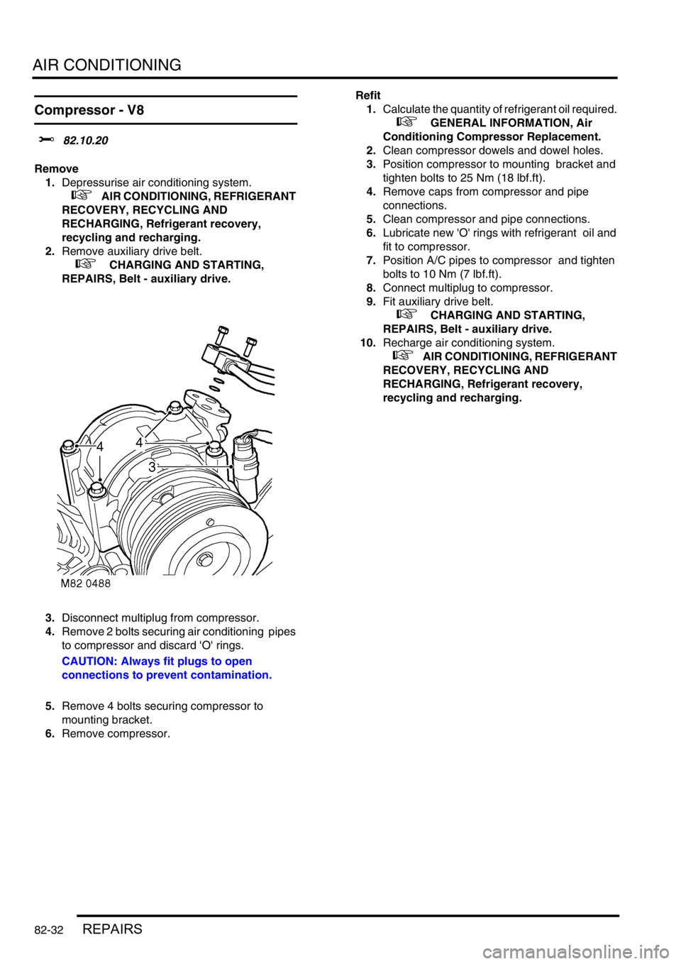
3.Disconnect multiplug from compressor.
4.Remove 2 bolts securing air conditioning pipes
to compressor and discard 'O' rings.
CAUTION: Always fit plugs to open
connections to prevent contamination.
5.Remove 4 bolts securing compressor to
mounting bracket.
6.Remove compressor.Refit
1.Calculate the quantity of refrigerant oil required.
+ GENERAL INFORMATION, Air
Conditioning Compressor Replacement.
2.Clean compressor dowels and dowel holes.
3.Position compressor to mounting bracket and
tighten bolts to 25 Nm (18 lbf.ft).
4.Remove caps from compressor and pipe
connections.
5.Clean compressor and pipe connections.
6.Lubricate new 'O' rings with refrigerant oil and
fit to compressor.
7.Position A/C pipes to compressor and tighten
bolts to 10 Nm (7 lbf.ft).
8.Connect multiplug to compressor.
9.Fit auxiliary drive belt.
+ CHARGING AND STARTING,
REPAIRS, Belt - auxiliary drive.
10.Recharge air conditioning system.
+ AIR CONDITIONING, REFRIGERANT
RECOVERY, RECYCLING AND
RECHARGING, Refrigerant recovery,
recycling and recharging.
Page 1450 of 1672
CHARGING AND STARTING
REPAIRS 86-1-1
CHARGING AND STARTING REPAIRS
Alternator - diesel
$% 86.10.02
Remove
1.Remove auxiliary drive belt.
+ CHARGING AND STARTING,
REPAIRS, Belt - auxiliary drive.
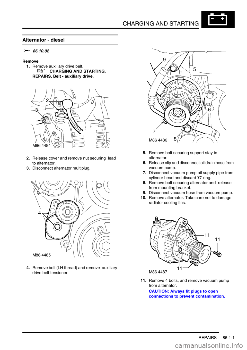
2.Release cover and remove nut securing lead
to alternator.
3.Disconnect alternator multiplug.
4.Remove bolt (LH thread) and remove auxiliary
drive belt tensioner. 5.Remove bolt securing support stay to
alternator.
6.Release clip and disconnect oil drain hose from
vacuum pump.
7.Disconnect vacuum pump oil supply pipe from
cylinder head and discard 'O' ring.
8.Remove bolt securing alternator and release
from mounting bracket.
9.Disconnect vacuum hose from vacuum pump.
10.Remove alternator. Take care not to damage
radiator cooling fins.
11.Remove 4 bolts, and remove vacuum pump
from alternator.
CAUTION: Always fit plugs to open
connections to prevent contamination.
Page 1451 of 1672
CHARGING AND STARTING
86-1-2 REPAIRS
Refit
1.Clean mating faces of alternator and vacuum
pump.
2.Fit vacuum pump to alternator and tighten
bolts to 8 Nm (6 lbf.ft).
3.Position alternator to engine and connect
multiplug.
4.Connect vacuum hose and oil drain hose to
vacuum pump and secure clips.
5.With assistance align alternator to mounting
bracket and fit but do not tighten bolt.
6.Fit bolt securing support stay to alternator and
tighten to 25 Nm (18 lbf.ft) .
7.Tighten bolt securing alternator to mounting
bracket to 45 Nm (33 lbf.ft).
8.Using new 'O' ring, connect oil supply pipe to
cylinder head and tighten to 10 Nm (7 lbf.ft).
9.Connect lead to alternator and tighten nut to 6
Nm (4.4 lbf.ft).
10.Fit auxiliary drive belt tensioner and tighten bolt
to 50 Nm (37 lbf.ft).
11.Fit auxiliary drive belt.
+ CHARGING AND STARTING,
REPAIRS, Belt - auxiliary drive.
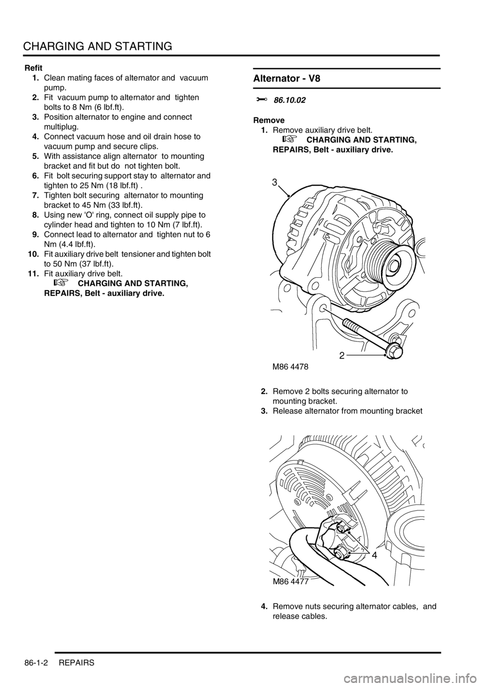
Alternator - V8
$% 86.10.02
Remove
1.Remove auxiliary drive belt.
+ CHARGING AND STARTING,
REPAIRS, Belt - auxiliary drive.
2.Remove 2 bolts securing alternator to
mounting bracket.
3.Release alternator from mounting bracket
4.Remove nuts securing alternator cables, and
release cables.
Page 1452 of 1672
CHARGING AND STARTING
REPAIRS 86-1-3
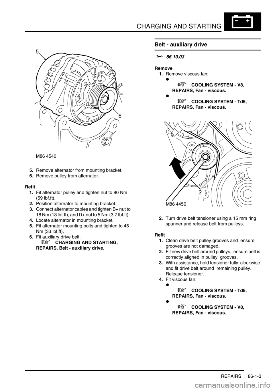
5.Remove alternator from mounting bracket.
6.Remove pulley from alternator.
Refit
1.Fit alternator pulley and tighten nut to 80 Nm
(59 lbf.ft).
2.Position alternator to mounting bracket.
3.Connect alternator cables and tighten B+ nut to
18 Nm (13 lbf.ft), and D+ nut to 5 Nm (3.7 lbf.ft).
4.Locate alternator in mounting bracket.
5.Fit alternator mounting bolts and tighten to 45
Nm (33 lbf.ft).
6.Fit auxiliary drive belt.
+ CHARGING AND STARTING,
REPAIRS, Belt - auxiliary drive.
Belt - auxiliary drive
$% 86.10.03
Remove
1.Remove viscous fan:
l
+ COOLING SYSTEM - V8,
REPAIRS, Fan - viscous.
l
+ COOLING SYSTEM - Td5,
REPAIRS, Fan - viscous.
2.Turn drive belt tensioner using a 15 mm ring
spanner and release belt from pulleys.
Refit
1.Clean drive belt pulley grooves and ensure
grooves are not damaged.
2.Fit new drive belt around pulleys, ensure belt is
correctly aligned in pulley grooves.
3.With assistance, hold tensioner fully clockwise
and fit drive belt around remaining pulley.
Release tensioner.
4.Fit viscous fan:
l
+ COOLING SYSTEM - Td5,
REPAIRS, Fan - viscous.
l
+ COOLING SYSTEM - V8,
REPAIRS, Fan - viscous.
Page 1481 of 1672

BODY CONTROL UNIT
86-3-12 DESCRIPTION AND OPERATION
Seatbelt warning lamp Timed The warning lamp is on for 6 seconds after the ignition is turned
on.
Buckle The warning lamp is on for 6 seconds after ignition is turned on or
until the buckle is fastened.
Ignition II If the buckle is unfastened when the ignition is turned on then the
warning lamp comes on for 6 seconds.
Disable The warning lamp is not used.
Seatbelt audible warning Timed The audible warning is on for 6 seconds after the ignition is turned
on.
Buckle The audible warning is on for 6 seconds after the ignition is turned
on or until the buckle is fastened.
Ignition II If the buckle is unfastened when the ignition is turned on then the
audible warning is on for 6 seconds.
Disable The audible warning is not used.
Bulb failure warning Disabled Direction indicator bulb failure detection is disabled.
Enabled Direction indicator bulb failure detection is enabled.
Superlocking None Superlocking is not available.
Double The vehicle will superlock on a double press of the remote
transmitter or double key turn.
Single The vehicle will superlock on a single press of the remote
transmitter or a single key turn.
No key The vehicle will superlock on a single press of the remote
transmitter but not with the key.
Door unlocking Not SPE The SPE (Single Point Entry) function is not used. All doors unlock
on a remote transmitter press.
SPE Only the driver's door unlocks on the first remote transmitter press,
all other doors on the second press.
Alarm disarming Always Operation of the key in the driver's door always disarms the
vehicle.
Key only Operation of the key in the driver's door only disarms the vehicle
if it was locked with the key.
Key never The security system is not disarmed by the key (except for EKA).
Inertia switch No hazards Operation of the inertia switch does not operate the hazard
warning lamps.
Hazards Operation of the inertia switch operates the hazard warning lamps.
Speed locking Disabled Speed related locking is disabled.
Enabled Speed related locking is enabled. The door locks are disabled
when the vehicle is moving.
Volumetric sensing Disabled Volumetric sensing is disabled.
Enabled Volumetric sensing is enabled.
Alarm Disabled The vehicle is not fitted with a security system.
Enabled The vehicle is fitted with a security system.
Passive immobilisation Disabled Passive immobilisation is disabled.
Enabled Passive immobilisation is enabled.
Hazard warning lamps Disabled The hazard warning lamps do not flash on security system arm,
disarm or trigger.
Enabled The hazard warning lamps flash on security system trigger only.
All The hazards flash on security system arm, disarm and trigger.
Mislocking audible
warningDisabled Mislock audible warnings are disabled.
Enabled Mislock audible warnings are enabled. Function Option Details
Page 1487 of 1672

BODY CONTROL UNIT
86-3-18 DESCRIPTION AND OPERATION
Self levelling suspension and ABS
The BCU communicates with the SLABS ECU for several functions:
lAn output is provided from the SLABS ECU to the BCU to provide the logic conditions for issuing the SLS audible
warning.
lThe BCU receives an input from the SLABS ECU relating to the raise/ lower command from the remote handset.
+ REAR SUSPENSION, DESCRIPTION AND OPERATION, Description - SLS.
Hill descent control
The BCU provides an output signal to the SLABS ECU for automatic transmission in neutral for HDC control. The
BCU checks the status of the ignition and 'gearbox state' inputs and provides a 'Neutral selected' output. If the ignition
is on and 'gearbox state' is Neutral, the 'Neutral selected' output is on, otherwise 'Neutral selected' is off.
+ BRAKES, DESCRIPTION AND OPERATION, Description.
Heated screens
The Heated Front Screen (HFS) is fitted for some market destinations and is operated from a non-latching switch
located on the instrument pack cowl. The BCU will only allow the heated front screen to operate when the engine is
running and controls the time-out period for switching the circuit off.
The heated front screen operation can also be controlled from the Automatic Temperature Control (ATC) ECU on
vehicles fitted with air conditioning.
The heated rear window will only function when the engine is running, and is operated by a non-latching switch on the
instrument pack cowl. The heated rear window can also be operated by the ATC ECU on vehicles fitted with air
conditioning.
Interior courtesy lamps
The BCU controls the operation of the interior courtesy lamps. The courtesy lamps are situated in the front, mid and
rear areas of the headlining.
Fuel flap actuator
The BCU provides an earth path to the fuel flap release solenoid to allow the fuel filler flap to be opened. This is only
allowed if the alarm system is not set and all other conditions have been satisfied. The fuel flap release switch is
located in the fascia switch pack and it receives a voltage supply from the passenger compartment fuse box.
Audible warnings
The BCU can request the instrument pack to generate an audible warning in response to conditions it has detected
and which need to be drawn to the driver's attention. One of six different audible warnings can be requested by the
BCU.
Sound request number Sound functions Priority (1 = lowest, 6 = highest)
0Off 1
1 Seat belt warning 6
2 Key-in warning 3
3 SLABS/ HDC warning 4
4 Transfer box in neutral warning 5
5 Lights on warning 2