Page 1157 of 1672

INTERIOR TRIM COMPONENTS
76-3-4 REPAIRS
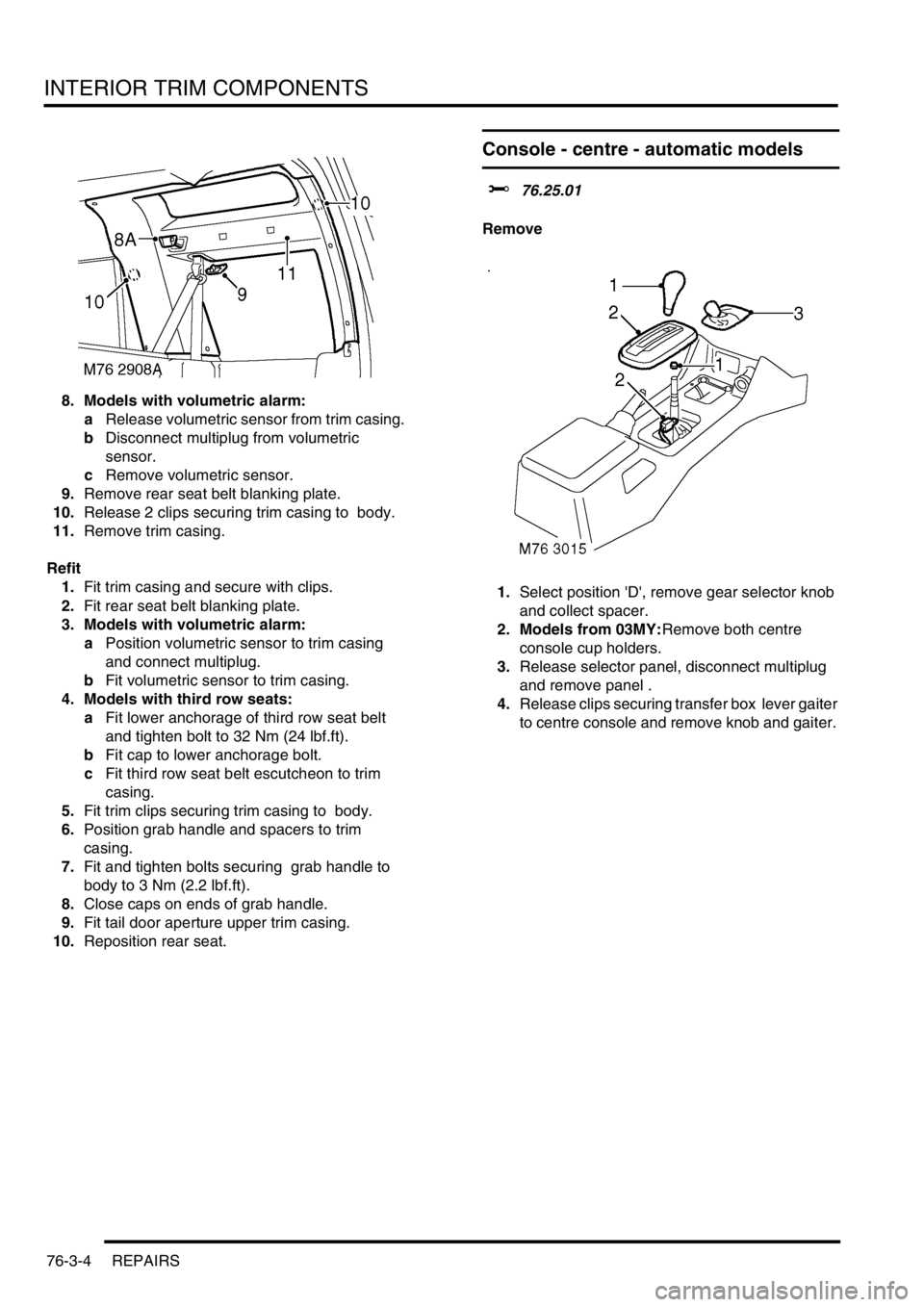
8. Models with volumetric alarm:
aRelease volumetric sensor from trim casing.
bDisconnect multiplug from volumetric
sensor.
cRemove volumetric sensor.
9.Remove rear seat belt blanking plate.
10.Release 2 clips securing trim casing to body.
11.Remove trim casing.
Refit
1.Fit trim casing and secure with clips.
2.Fit rear seat belt blanking plate.
3. Models with volumetric alarm:
aPosition volumetric sensor to trim casing
and connect multiplug.
bFit volumetric sensor to trim casing.
4. Models with third row seats:
aFit lower anchorage of third row seat belt
and tighten bolt to 32 Nm (24 lbf.ft).
bFit cap to lower anchorage bolt.
cFit third row seat belt escutcheon to trim
casing.
5.Fit trim clips securing trim casing to body.
6.Position grab handle and spacers to trim
casing.
7.Fit and tighten bolts securing grab handle to
body to 3 Nm (2.2 lbf.ft).
8.Close caps on ends of grab handle.
9.Fit tail door aperture upper trim casing.
10.Reposition rear seat.
Console - centre - automatic models
$% 76.25.01
Remove
1.Select position 'D', remove gear selector knob
and collect spacer.
2. Models from 03MY:Remove both centre
console cup holders.
3.Release selector panel, disconnect multiplug
and remove panel .
4.Release clips securing transfer box lever gaiter
to centre console and remove knob and gaiter.
Page 1172 of 1672

INTERIOR TRIM COMPONENTS
REPAIRS 76-3-19
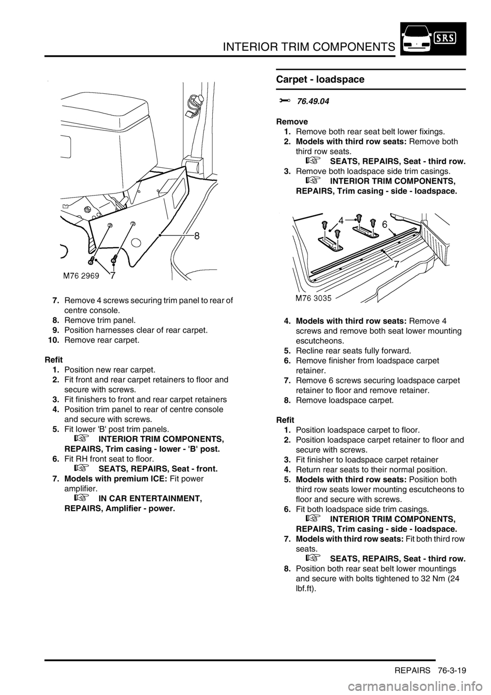
7.Remove 4 screws securing trim panel to rear of
centre console.
8.Remove trim panel.
9.Position harnesses clear of rear carpet.
10.Remove rear carpet.
Refit
1.Position new rear carpet.
2.Fit front and rear carpet retainers to floor and
secure with screws.
3.Fit finishers to front and rear carpet retainers
4.Position trim panel to rear of centre console
and secure with screws.
5.Fit lower 'B' post trim panels.
+ INTERIOR TRIM COMPONENTS,
REPAIRS, Trim casing - lower - 'B' post.
6.Fit RH front seat to floor.
+ SEATS, REPAIRS, Seat - front.
7. Models with premium ICE: Fit power
amplifier.
+ IN CAR ENTERTAINMENT,
REPAIRS, Amplifier - power.
Carpet - loadspace
$% 76.49.04
Remove
1.Remove both rear seat belt lower fixings.
2. Models with third row seats: Remove both
third row seats.
+ SEATS, REPAIRS, Seat - third row.
3.Remove both loadspace side trim casings.
+ INTERIOR TRIM COMPONENTS,
REPAIRS, Trim casing - side - loadspace.
4. Models with third row seats: Remove 4
screws and remove both seat lower mounting
escutcheons.
5.Recline rear seats fully forward.
6.Remove finisher from loadspace carpet
retainer.
7.Remove 6 screws securing loadspace carpet
retainer to floor and remove retainer.
8.Remove loadspace carpet.
Refit
1.Position loadspace carpet to floor.
2.Position loadspace carpet retainer to floor and
secure with screws.
3.Fit finisher to loadspace carpet retainer
4.Return rear seats to their normal position.
5. Models with third row seats: Position both
third row seats lower mounting escutcheons to
floor and secure with screws.
6.Fit both loadspace side trim casings.
+ INTERIOR TRIM COMPONENTS,
REPAIRS, Trim casing - side - loadspace.
7. Models with third row seats: Fit both third row
seats.
+ SEATS, REPAIRS, Seat - third row.
8.Position both rear seat belt lower mountings
and secure with bolts tightened to 32 Nm (24
lbf.ft).
Page 1200 of 1672
SEATS
REPAIRS 76-5-15
REPAIRS
Seat - front
$% 78.10.43.99
Remove
1.Disconnect battery earth lead.
2.Remove 3 screws and 1 trim clip securing
lower trim casing to seat.
3.Remove lower trim casing.
4.Remove cap from front seat belt lower
anchorage bolt.
5.Remove front seat belt lower anchorage bolt. 6.Remove 4 Torx bolts and nut securing front
seat to floor.
7.Lean seat forward to gain access to multiplugs.
Page 1201 of 1672
SEATS
76-5-16 REPAIRS
8.Release pretensioner multiplug from seat
frame and disconnect.
9. Electrically operated seats: Disconnect 2
seat motor multiplugs.
10.Remove front seat.
Refit
1.Fit front seat in vehicle.
2. Electrically operated seats: Connect seat
motor multiplugs.
3.Connect pretensioner multiplug and secure to
seat frame.
4.Fit Torx bolts and nut securing front seat to floor
and tighten to 45 Nm (33 lbf.ft).
5.Fit front seat belt lower anchorage bolt to front
seat and tighten to 32 Nm (24 lbf.ft).
6.Fit cap to lower anchorage bolt.
7.Fit lower trim casing to seat and secure with
screws and trim clip.
8.Connect battery earth lead.
Seat - third row
$% 78.10.45
Remove
1.Manufacture a spring retainer bracket to the
dimensions given above.
2.Position third row seat in deployed position.
3.Remove the cup holder (where applicable).
Page 1213 of 1672
SEATS
76-5-28 REPAIRS
Cover - squab - RH rear seat
$% 78.90.13
Remove
1.Remove rear seat.
+ SEATS, REPAIRS, Seat - rear.
2.Remove centre rear seat belt.
+ RESTRAINT SYSTEMS, REPAIRS,
Seat belt - rear - centre.
3.Remove 2 screws securing end cover and
remove end cover.
4.Remove both head restraint guide tubes. 5.Remove 2 screws securing squab release
lever, release cable and remove lever
assembly.
6.Release catches securing arm rest supports,
lower arm rest, release arm rest hinge catches
and remove arm rest assembly.
7.Release squab from 10 hooks in arm rest
recess.
Page 1214 of 1672

SEATS
REPAIRS 76-5-29
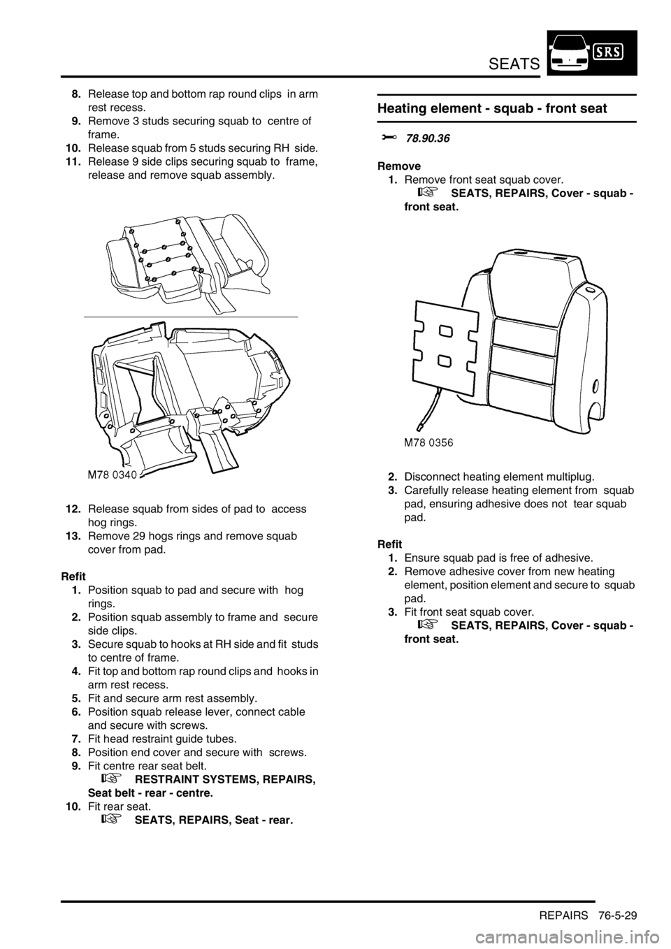
8.Release top and bottom rap round clips in arm
rest recess.
9.Remove 3 studs securing squab to centre of
frame.
10.Release squab from 5 studs securing RH side.
11.Release 9 side clips securing squab to frame,
release and remove squab assembly.
12.Release squab from sides of pad to access
hog rings.
13.Remove 29 hogs rings and remove squab
cover from pad.
Refit
1.Position squab to pad and secure with hog
rings.
2.Position squab assembly to frame and secure
side clips.
3.Secure squab to hooks at RH side and fit studs
to centre of frame.
4.Fit top and bottom rap round clips and hooks in
arm rest recess.
5.Fit and secure arm rest assembly.
6.Position squab release lever, connect cable
and secure with screws.
7.Fit head restraint guide tubes.
8.Position end cover and secure with screws.
9.Fit centre rear seat belt.
+ RESTRAINT SYSTEMS, REPAIRS,
Seat belt - rear - centre.
10.Fit rear seat.
+ SEATS, REPAIRS, Seat - rear.
Heating element - squab - front seat
$% 78.90.36
Remove
1.Remove front seat squab cover.
+ SEATS, REPAIRS, Cover - squab -
front seat.
2.Disconnect heating element multiplug.
3.Carefully release heating element from squab
pad, ensuring adhesive does not tear squab
pad.
Refit
1.Ensure squab pad is free of adhesive.
2.Remove adhesive cover from new heating
element, position element and secure to squab
pad.
3.Fit front seat squab cover.
+ SEATS, REPAIRS, Cover - squab -
front seat.
Page 1244 of 1672
CHASSIS AND BODY DIMENSIONS
BODY DIMENSIONS 77-1-11
Internal information
I.D Description Length
A Distance between seat belt anchorage top fixing and
seat belt reel lower fixing1814.5 (71.437)
B Distance between seat belt anchorage lower fixings on
wheel arch inner1430.2 (56.307)
M77 1760
A
B
Page 1262 of 1672

PANEL REPAIRS
PROCEDURES 77-2-13
PROCEDURES
General welding precautions
General
For ease of reference, the diagrams on the following pages show only the type of weld used in repair where it varies
from that used in production.
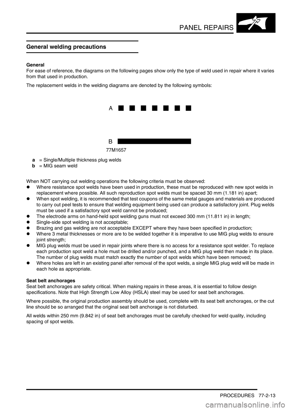
The replacement welds in the welding diagrams are denoted by the following symbols:
a = Single/Multiple thickness plug welds
b = MIG seam weld
When NOT carrying out welding operations the following criteria must be observed:
lWhere resistance spot welds have been used in production, these must be reproduced with new spot welds in
replacement where possible. All such reproduction spot welds must be spaced 30 mm (1.181 in) apart;
lWhen spot welding, it is recommended that test coupons of the same metal gauges and materials are produced
to carry out peel tests to ensure that welding equipment being used can produce a satisfactory joint. Plug welds
must be used if a satisfactory spot weld cannot be produced;
lThe electrode arms on hand-held spot welding guns must not exceed 300 mm (11.811 in) in length;
lSingle-side spot welding is not acceptable;
lBrazing and gas welding are not acceptable EXCEPT where they have been specified in production;
lWhere 3 metal thicknesses or more are to be welded together it is imperative to use MIG plug welds to ensure
joint strength;
lMIG plug welds must be used in repair joints where there is no access for a resistance spot welder. To replace
each production spot weld a hole must be drilled and/or punched, and a MIG plug weld then made in its place.
The number of plug welds must match exactly the number of spot welds which have been removed;
lWhere holes are left in an existing panel after removal of the spot welds, a single MIG plug weld will be made in
each hole as appropriate.
Seat belt anchorages
Seat belt anchorages are safety critical. When making repairs in these areas, it is essential to follow design
specifications. Note that High Strength Low Alloy (HSLA) steel may be used for seat belt anchorages.
Where possible, the original production assembly should be used, complete with its seat belt anchorages, or the cut
line should be so arranged that the original seat belt anchorage is not disturbed.
All welds within 250 mm (9.842 in) of seat belt anchorages must be carefully checked for weld quality, including
spacing of spot welds.