Page 1506 of 2100
6E±539
6VE1 3.5L ENGINE DRIVEABILITY AND EMISSIONS
4. Remove the ECT sensor from the coolant crossover.
014RY00002
Installation Procedure
1. Apply sealer or the equivalent to the threads of the
ECT sensor.
2. Install the ECT sensor in the coolant crossover.
Tighten
�Tighten the ECT sensor to 30 N´m (22 lb ft.).
014RY00002
3. Connect the electrical connector.
014RY00003
4. Fill the radiator with coolant. Refer to Draining and
Refilling Cooling System
in Engine Cooling section.
5. Connect the negative battery cable.
Heated Oxygen Sensor (HO2S)
Removal Procedure
1. Disconnect the negative battery cable.
2. Locate the four oxygen sensors.
060RW008
Page 1507 of 2100
6E±540
6VE1 3.5L ENGINE DRIVEABILITY AND EMISSIONS
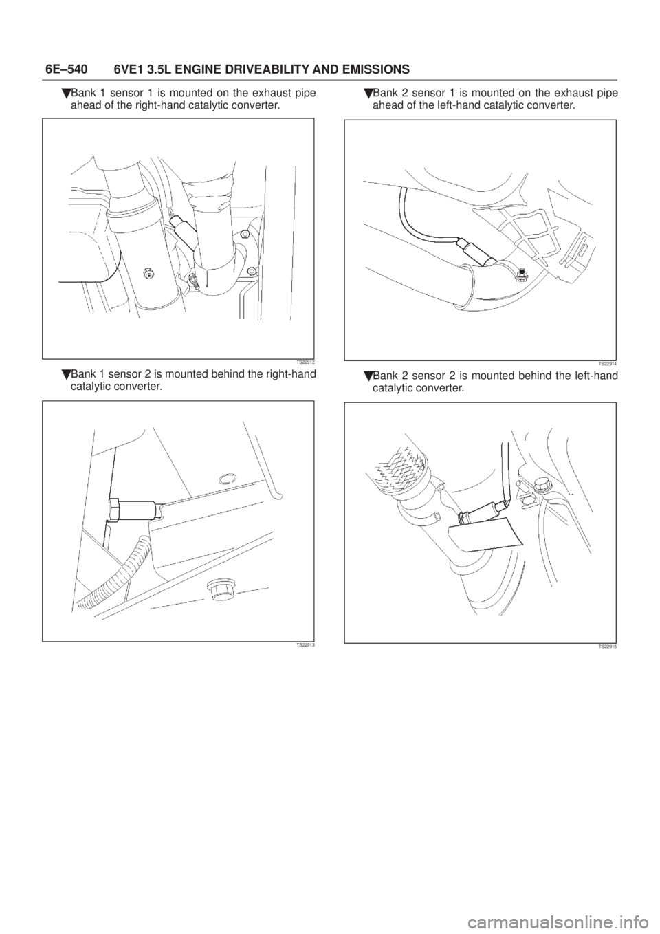
�Bank 1 sensor 1 is mounted on the exhaust pipe
ahead of the right-hand catalytic converter.
TS22912
�Bank 1 sensor 2 is mounted behind the right-hand
catalytic converter.
TS22913
�Bank 2 sensor 1 is mounted on the exhaust pipe
ahead of the left-hand catalytic converter.
TS22914
�Bank 2 sensor 2 is mounted behind the left-hand
catalytic converter.
TS22915
Page 1508 of 2100

6E±541
6VE1 3.5L ENGINE DRIVEABILITY AND EMISSIONS
3. Disconnect the pigtail from the wiring harness.
060RY00128
IMPORTANT:The pigtail is permanently attached to
the sensor. Be careful not to pull the wires out.
NOTE: Do not use a torch to remove an HO2S unless the
sensor is being replaced. Using a torch could damage the
sensor.
4. Remove the sensor from the exhaust pipe.
�Because of the expansion and contraction of the
metal in the exhaust system over time, this may be
difficult if the engine temperature is below 48�C
(120�F).
060RY00128
Inspection Procedure
All four sensors are identical. Inspect each in the same
way.
1. Inspect the pigtail and the electrical connector for
grease, dirt, corrosion, and bare wires or worn
insulation.
2. Inspect the louvered end of the sensor for grease,
dirt, or other contaminations.
060RY00128
Installation Procedure
IMPORTANT:
�There is a special anti-seize compound on the HO2S
threads. This compound consists of glass beads
suspended in a liquid graphite solution. The graphite
burns away with engine heat, but the glass beads will
remain, making the sensor easier to remove.
�New or service sensors will already have the
compound applied to the threads. If a sensor is
removed and is to be reinstalled for any reason, the
threads must have anti-seize compound applied.
1. Apply anti-seize compound or the equivalent to the
threads of the oxygen sensor, if necessary.
2. Install the oxygen sensor on the exhaust pipe in its
original position.
Tighten
�Tighten the oxygen sensor to 55 N´m (40 lb ft.).
060RY00128
3. Connect the pigtail to the wiring harness.
4. Connect the negative battery cable.
Page 1509 of 2100

Sensor
Removal Procedure
1. Disconnect the negative battery cable.
2. Remove the engine cover
3. The IAT sensor is loca")
6E±542
6VE1 3.5L ENGINE DRIVEABILITY AND EMISSIONS
Intake Air Temperature (IAT)
Sensor
Removal Procedure
1. Disconnect the negative battery cable.
2. Remove the engine cover
3. The IAT sensor is located in the intake air duct, behind
the throttle body.
4. Disconnect the electrical connector from the IAT
sensor.
TS23741
5. Remove the IAT sensor from the intake air duct by
using a rocking motion while pulling the sensor.
Installation Procedure
1. Install the IAT sensor into the grommet in the intake
air duct.
2. Correct the IAT electrical connector.
TS23741
3. Install the engine cover.
4. Connect the negative battery cable.
ION Sensing Module
Removal Procedure
1. Disconnect the negative battery cable.
2. Disconnect the ION sensing module connector.
3. Remove the bolts and the ION sensing module from
the common chamber.
060RY00087
Installation Procedure
1. Install the ION sensing module on the common
chamber with the bolts.
Tighten
�Tighten the ION sensing module to 4 N´m (35 lb
in.).
Page 1510 of 2100
6E±543
6VE1 3.5L ENGINE DRIVEABILITY AND EMISSIONS
2. Connect the ION sensing module connectors as
shown in the illustration.
060RY00003
Legend
(1) Green Color Connector
(2) Blue Color Connector
3. Connect the negative battery cable.
Mass Air Flow (MAF) Sensor
Removal Procedure
1. Disconnect the negative battery cable.
2. Disconnect the electrical connector from the MAF
sensor.
TS23740
3. Loosen the clamps which secure the intake air duct
and the air cleaner to the MAF sensor.4. Remove the intake air duct from the MAF sensor.
5. Remove the MAF sensor from the air cleaner.
TS23781
Installation Procedure
1. Install the MAF sensor on the air cleaner with the
clamp.
2. Install the intake air duct and the clamp on the MAF
sensor.
TS23781
3. Tighten the clamps to secure the MAF sensor to the
intake air duct and the air cleaner.
4. Connect the MAF electrical connector.
5. Connect the negative battery cable.
Page 1511 of 2100
6E±544
6VE1 3.5L ENGINE DRIVEABILITY AND EMISSIONS
Manifold Absolute Pressure
(MAP) Sensor
Removal Procedure
1. Disconnect the negative battery cable.
2. Disconnect the electrical connector from the MAP
sensor.
055RY00001
3. Remove the bolt securing the MAP sensor to the
mounting bracket on the common chamber.
4. Remove the MAP sensor from the mounting bracket.
055RW002
Installation Procedure
1. Install the MAP sensor in the mounting bracket.
055RW002
2. Install the mounting bracket retaining bolt on the
common chamber.
Tighten
�Tighten the bolt to 20 N´m (12 lb ft.).
3. Connect the MAP electrical connector.
055RY00001
4. Connect the negative battery cable.
Page 1514 of 2100
 is a permanent memory that is
physically soldered with")
6E±547
6VE1 3.5L ENGINE DRIVEABILITY AND EMISSIONS
EEPROM
General Description
The Electronically Erasable Programmable Read Only
Memory (EEPROM) is a permanent memory that is
physically soldered within the PCM. The EEPROM
contains program and calibration information that the
PCM needs to control powertrain operation.
EEPROM Programming
1. Set-up ± Ensure that the following conditions have
been met:
�The battery is fully charged.
�The ignition is ªON.º
�The Vehicle Interface Module cable connection at
the DLC is secure.
2. Program the PCM using the latest software matching
the vehicle. Refer to up-to-date Techline equipment
user's instructions.
3. If the PCM fails to program, proceed as follows:
�Ensure that all PCM connections are OK.
�Check the Techline equipment for the latest
software version.
�Attempt to program the PCM. If the PCM still
cannot be programmed properly, replace the PCM.
The replacement PCM must be programmed.
Functional Check
1. Perform the On-Board Diagnostic System Check.
2. Start the engine and run for one minute.
3. Scan for DTCs using the Tech 2.
Throttle Position (TP) Sensor
Removal Procedure
1. Disconnect the negative battery cable.
2. Disconnect the TPS electrical connector.3. Remove the bolts and the TP sensor from the throttle
body.
060RY00159
NOTE: Do not clean the TP sensor by soaking it in
solvent. The sensor will be damaged as a result.
Function Check
Use a Tech 2 to check the TP sensor output voltage at
closed throttle.
�The voltage should be TP1 about 0.4V, TP2 about
4.6V and TP3 about 4.6V.
�If the reading is abnormal value, check the throttle
shaft to see if it is binding.
Installation Procedure
1. Install the TP sensor on the throttle body with the
bolts.
060RY00159
2. Connect the TP electrical connector.
3. Install the negative battery cable.
Page 1515 of 2100

Removal Procedure
CAUTION: The VSS is located on the right side of
the transfer case just ahead of the rear propeller
sha")
6E±548
6VE1 3.5L ENGINE DRIVEABILITY AND EMISSIONS
Vehicle Speed Sensor (VSS)
Removal Procedure
CAUTION: The VSS is located on the right side of
the transfer case just ahead of the rear propeller
shaft and very close to the exhaust pipes for 4WD
and on the extension cover for 2WD. Be sure that the
exhaust pipes are cool enough to touch before trying
to remove the VSS. If the pipes are hot, you could be
burned.
1. Disconnect the negative battery cable.
2. Disconnect the VSS electrical connector.
TS23748
3. Remove the bolt and the clamp securing the VSS in
place.
IMPORTANT:Have a container ready to catch any fluid
that leaks out when the VSS is removed from the transfer
case for 4WD and on the extension cover for 2WD.
TS23780
4. Remove the VSS from the transfer case by wiggling it
slightly and pulling it straight out.
Inspection Procedure
1. Inspect the electrical connector for signs of corrosion
or warping. Replace the VSS if the electrical
connector is corroded or warped.
2. Inspect the VSS driven gear for chips, breaks, or worn
condition. Replace the VSS if the driven gear is
chipped, broken or worn.
3. Inspect the O-ring for wear, nicks, tears, or
looseness. Replace the O-ring if necessary.
Installation Procedure
1. Install the VSS in the transfer case with the notch for
the connector facing the rear.
2. Secure the VSS in place with the clamp and the bolt.
Tighten
�Tighten the bolt to 16 N´m (12 lb ft.).
TS23780
3. Connect the VSS electrical connector.
TS23748
4. Check the transfer case oil level. Add fluid if
necessary.
5. Connect the negative battery cable.

 Green Color Connector
(2) Blue Color Connector
3. C")
 Sensor
Removal Procedure
1. Disconnect the negative battery cable.
2. Disconnect the electrical connector from the")