Page 1772 of 2100
TRANSMISSION CONTROL SYSTEM (4L30±E)7A1±85
D07R200013
Page 1773 of 2100
7A1±86
TRANSMISSION CONTROL SYSTEM (4L30±E)
Parts Location
D07R200014
Legend
(1) Connector I±10
(2) Connector E±44
(3) Connector I±22
(4) Connector I±23
(5) Connector I±24
(6) Data Link Connector C±39
(7) Connector H±9, H±11, H±16
(8) Connector I±32
(9) Connector I±31
(10) Connector B±16(11) Powertrain Control Module (PCM) Connector
E±34, E±35
(12) Connector H±3, H±5, H±6
(13) Connector E±42
(14) Connector E±41
(15) Connector E±40
(16) Connector E±11
(17) Connector E±33
(18) Connector X±11
(19) Connector H±8, H±14, H±17, H±18
(20) Connector E±7
Page 1774 of 2100
TRANSMISSION CONTROL SYSTEM (4L30±E)7A1±87
Harness Connector Faces
No.Connector face
B-16
C-39
E-7
E-11
E-33
E-34
(J1)
E-35
(J2)
E-40
E-41
No.Connector face
E-42
E-44
H-3
H-5
H-6
H-8
H-9
H-11
H-14
Page 1775 of 2100
7A1±88
TRANSMISSION CONTROL SYSTEM (4L30±E)
No.Connector face
H-16
H-17
H-18
I-10
I-22
I-23
I-24
I-31
I-32
No.Connector face
X-11
Page 1776 of 2100
TRANSMISSION CONTROL SYSTEM (4L30±E)7A1±89
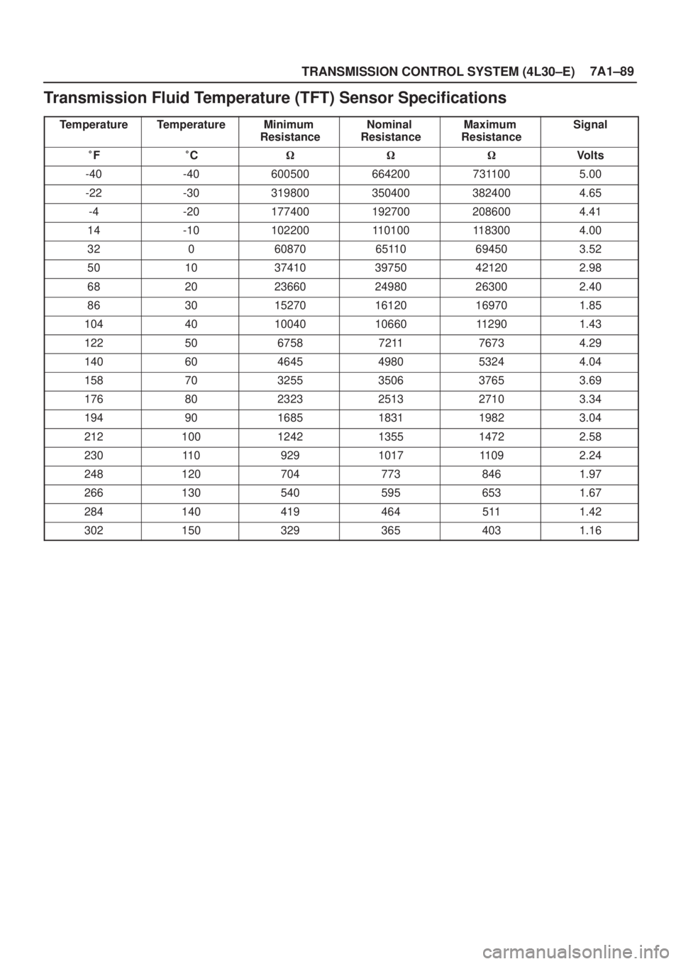
Transmission Fluid Temperature (TFT) Sensor Specifications
TemperatureTemperatureMinimum
ResistanceNominal
ResistanceMaximum
ResistanceSignal
�F�C���Volts
-40-406005006642007311005.00
-22-303198003504003824004.65
-4-201774001927002086004.41
14-101022001101001183004.00
3206087065110694503.52
50103741039750421202.98
68202366024980263002.40
86301527016120169701.85
104401004010660112901.43
122506758721176734.29
140604645498053244.04
158703255350637653.69
176802323251327103.34
194901685183119823.04
2121001242135514722.58
23011 0929101711092.24
2481207047738461.97
2661305405956531.67
2841404194645111.42
3021503293654031.16
Page 1867 of 2100

METER AND GAUGE8E±1
AXIOM
BODY AND ACCESSORIES
METER AND GAUGE
CONTENTS
Service Precaution 8E±1. . . . . . . . . . . . . . . . . . . . . .
General Description 8E±1. . . . . . . . . . . . . . . . . . . . .
Meter Assembly 8E±2. . . . . . . . . . . . . . . . . . . . . . . . .
General Description 8E±2. . . . . . . . . . . . . . . . . . . . .
Layout for Meters/Gauges, Warning Lights,
Indicator Lights and Illumination Lights 8E±2. . .
Table for Meter/Gauge Connector Terminal
Connections 8E±4. . . . . . . . . . . . . . . . . . . . . . . . . .
Removal 8E±6. . . . . . . . . . . . . . . . . . . . . . . . . . . . .
Installation 8E±6. . . . . . . . . . . . . . . . . . . . . . . . . . . .
Warning Light Bulb and Indicator Light Bulb 8E±6. Removal 8E±6. . . . . . . . . . . . . . . . . . . . . . . . . . . . .
Installation 8E±6. . . . . . . . . . . . . . . . . . . . . . . . . . . .
A/T Shift Indicator Light Bulb 8E±7. . . . . . . . . . . . . .
Removal 8E±7. . . . . . . . . . . . . . . . . . . . . . . . . . . . .
Installation 8E±8. . . . . . . . . . . . . . . . . . . . . . . . . . . .
Vehicle Speed Sensor 8E±9. . . . . . . . . . . . . . . . . . .
Removal 8E±9. . . . . . . . . . . . . . . . . . . . . . . . . . . . .
Installation 8E±9. . . . . . . . . . . . . . . . . . . . . . . . . . . .
Fuel Tank Unit 8E±9. . . . . . . . . . . . . . . . . . . . . . . . . .
Removal 8E±9. . . . . . . . . . . . . . . . . . . . . . . . . . . . .
Main Data and Specifications 8E±10. . . . . . . . . . . . .
Service Precaution
WARNING: THIS VEHICLE HAS A SUPPLEMENTAL
RESTRAINT SYSTEM (SRS). REFER TO THE SRS
COMPONENT AND WIRING LOCATION VIEW IN
ORDER TO DETERMINE WHETHER YOU ARE
PERFORMING SERVICE ON OR NEAR THE SRS
COMPONENTS OR THE SRS WIRING. WHEN YOU
ARE PERFORMING SERVICE ON OR NEAR THE SRS
COMPONENTS OR THE SRS WIRING, REFER TO
THE SRS SERVICE INFORMATION. FAILURE TO
FOLLOW WARNINGS COULD RESULT IN POSSIBLE
AIR BAG DEPLOYMENT, PERSONAL INJURY, OR
OTHERWISE UNNEEDED SRS SYSTEM REPAIRS.
CAUTION: Always use the correct fastener in the
proper location. When you replace a fastener, use
ONLY the exact part number for that application.
ISUZU will call out those fasteners that require a
replacement after removal. ISUZU will also call out
the fasteners that require thread lockers or thread
sealant. UNLESS OTHERWISE SPECIFIED, do not
use supplemental coatings (Paints, greases, or other
corrosion inhibitors) on threaded fasteners or
fastener joint interfaces. Generally, such coatings
adversely affect the fastener torque and the joint
clamping force, and may damage the fastener. When
you install fasteners, use the correct tightening
sequence and specifications. Following these
instructions can help you avoid damage to parts and
systems.
General Description
The circuit consists of the starter switch, meter assembly,
vehicle speed sensor, transmission switch, lighting
switch, turn signal switch, thermo unit, oil pressure unit,
Powertrain Control Module (PCM), fuel tank unit, 4WD
switch, oil pressure switch, parking brake switch, brake
fluid switch, seat belt switch, illumination controller, meter
and ambient sensor.
Page 2099 of 2100
10A±3
CRUISE CONTROL SYSTEM
Powertrain Control Module (PCM)
Removal and Installation
Refer to Powertrain Control Module (PCM) in Engine
section.
Mode Switch
Removal and Installation
Refer to Mode Switch removal and installation steps in
Automatic Transmission section.
Cruise Control Main Switch
Removal
1. Disconnect the battery ground cable.
2. Remove the meter cluster assembly (1).
�Refer to
Instrument Panel Assembly in Body
Structure section.
3. Remove the cruise control main switch (2).
�Disconnect the switch connector.
�Push the lock from the back side of the instrument
panel cluster assembly.
825R100019
Installation
To install, follow the removal steps in the reverse order.
Cruise Control Switch (Combination Switch)
Removal and Installation
Refer to Lighting Switch (Combination Switch) removal
and installation steps in Lighting System section.
Page 2100 of 2100

10A±4
CRUISE CONTROL SYSTEM
Diagnosis
Cruise control system is controlled by the PCM as well as
6VE1 engine and automatic transmission. DTC codes are
stored in the PCM if troubles occur in the circuit. DTC
codes categorized ªtype Dº are shown only by the Tech 2
scan tool. The following chart only shows some typical
DTCs for cruise control system. Refer to
PCM Diagnostic
Trouble Codes in Driveability and Emissions for entire
DTC diagnosis.
DTCTROUBLE
PARTDTC
TYPEMAJOR CONDITION OF
TROUBLEDIAGNOSIS PERIOD
P0565CRUISE MAIN
CIRCUITD�THE SWITCH CONTACT
REMAINS ON FOR 15
SECONDS OR MORE.
�NOISES ARE GENERATED
BY THE POOR SWITCH
CONTACT 60 TIMES WITHIN
1 SECOND.DIAGNOSIS IS ENABLED IN
130 SECONDS AFTER THE
SWITCH OPERATED.
P0566CRUISE CAN-
CEL CIRCUITD�THE SWITCH CONTACT
REMAINS ON FOR 40
SECONDS OR MORE.DIAGNOSIS IS ENABLED IN
120 SECONDS AFTER THE
SWITCH OPERATED.
P0567CRUISE RE-
SUME CIRCUITD�THE SWITCH CONTACT
REMAINS ON FOR 50
SECONDS OR MORE.
�NOISES ARE GENERATED
BY THE POOR SWITCH
CONTACT 100 TIMES
WITHIN 1.6 SECONDS.DIAGNOSIS IS ENABLED IN
110 SECONDS AFTER THE
SWITCH OPERATED.
P0568CRUISE SET
CIRCUITD�THE SWITCH CONTACT
REMAINS ON FOR 120
SECONDS OR MORE.
�NOISES ARE GENERATED
BY THE POOR SWITCH
CONTACT 100 TIMES
WITHIN 1.6 SECONDS.DIAGNOSIS IS ENABLED IN
125 SECONDS AFTER THE
SWITCH OPERATED.
DTC: Diagnostic Trouble Code
NOTE: The DTCs are detected while the engine is
running.
7A1±85
D07R200013")

Parts Location
D07R200014
Legend
(1) Connector I±10
(2) Connector E±44
(3) Connector I±22
(4) Connector I±23
(5) Connector I±24
(6) Data Link Connect")
7A1±87
Harness Connector Faces
No.Connector face
B-16
C-39
E-7
E-11
E-33
E-34
(J1)
E-35
(J2)
E-40
E-41
No.Connector face
E-42
E-44
H-3
H-5
H-6
H-8
H-9
H-11
H-14")

No.Connector face
H-16
H-17
H-18
I-10
I-22
I-23
I-24
I-31
I-32
No.Connector face
X-11")

Removal and Installation
Refer to Powertrain Control Module (PCM) in Engine
section.
Mode Switch
Removal and Installation
Refer to Mode Swi")