2002 DODGE RAM wheel
[x] Cancel search: wheelPage 163 of 2255

OPERATION
STANDARD DIFFERENTIAL
The axle receives power from the transmission/
transfer case through the rear propeller shaft. The
rear propeller shaft is connected to the pinion gear
which rotates the differential through the gear mesh
with the ring gear bolted to the differential case. The
engine power is transmitted to the axle shafts
through the pinion mate and side gears. The side
gears are splined to the axle shafts.
During straight-ahead driving, the differential pin-
ion gears do not rotate on the pinion mate shaft. This
occurs because input torque applied to the gears is
divided and distributed equally between the two side
gears. As a result, the pinion gears revolve with the
pinion mate shaft but do not rotate around it (Fig. 1).
When turning corners, the outside wheel must travel
a greater distance than the inside wheel to complete a
turn. The difference must be compensated for to prevent
the tires from scuffing and skidding through turns. To
accomplish this, the differential allows the axle shafts
to turn at unequal speeds (Fig. 2). In this instance, the
input torque applied to the pinion gears is not divided
equally. The pinion gears now rotate around the pinion
mate shaft in opposite directions. This allows the side
gear and axle shaft attached to the outside wheel to
rotate at a faster speed.
TRAC-LOKŸ DIFFERENTIAL
The Trac-lokŸ clutches are engaged by two concur-
rent forces. The first being the preload force exerted
through Belleville spring washers within the clutch
packs. The second is the separating forces generatedby the side gears as torque is applied through the
ring gear (Fig. 3).
The Trac-lokŸ design provides the differential
action needed for turning corners and for driving
straight ahead during periods of unequal traction.
When one wheel looses traction, the clutch packs
transfer additional torque to the wheel having the
most traction. Trac-lokŸ differentials resist wheel
spin on bumpy roads and provide more pulling power
when one wheel looses traction. Pulling power is pro-
vided continuously until both wheels loose traction. If
both wheels slip due to unequal traction, Trac-lokŸ
operation is normal. In extreme cases of differences
of traction, the wheel with the least traction may
spin.
DIAGNOSIS AND TESTING - AXLE
GEAR NOISE
Axle gear noise can be caused by insufficient lubri-
cant, incorrect backlash, incorrect pinion depth, tooth
contact, worn/damaged gears, or the carrier housing
not having the proper offset and squareness.
Gear noise usually happens at a specific speed
range. The noise can also occur during a specific type
of driving condition. These conditions are accelera-
tion, deceleration, coast, or constant load.
When road testing, first warm-up the axle fluid by
driving the vehicle at least 5 miles and then acceler-
ate the vehicle to the speed range where the noise is
the greatest. Shift out-of-gear and coast through the
peak-noise range. If the noise stops or changes
greatly:
²Check for insufficient lubricant.
²Incorrect ring gear backlash.
²Gear damage.
Differential side gears and pinions can be checked
by turning the vehicle. They usually do not cause
Fig. 1 STRAIGHT AHEAD DRIVING
1 - IN STRAIGHT AHEAD DRIVING EACH WHEEL ROTATES AT
100% OF CASE SPEED
2 - PINION GEAR
3 - SIDE GEAR
4 - PINION GEARS ROTATE WITH CASE
Fig. 2 ON TURNS
1 - PINION GEARS ROTATE ON PINION SHAFT
3 - 108 REAR AXLE - 286RBIBR/BE
REAR AXLE - 286RBI (Continued)
Page 164 of 2255

noise during straight-ahead driving when the gears
are unloaded. The side gears are loaded during vehi-
cle turns. A worn pinion shaft can also cause a snap-
ping or a knocking noise.
BEARING NOISE
The axle shaft, differential and pinion bearings can
all produce noise when worn or damaged. Bearing
noise can be either a whining, or a growling sound.
Pinion bearings have a constant-pitch noise. This
noise changes only with vehicle speed. Pinion bearing
noise will be higher pitched because it rotates at a
faster rate. Drive the vehicle and load the differen-
tial. If bearing noise occurs, the rear pinion bearing
is the source of the noise. If the bearing noise is
heard during a coast, the front pinion bearing is the
source.
Worn or damaged differential bearings usually pro-
duce a low pitch noise. Differential bearing noise issimilar to pinion bearing noise. The pitch of differen-
tial bearing noise is also constant and varies only
with vehicle speed.
Axle shaft bearings produce noise and vibration
when worn or damaged. The noise generally changes
when the bearings are loaded. Road test the vehicle.
Turn the vehicle sharply to the left and to the right.
This will load the bearings and change the noise
level. Where axle bearing damage is slight, the noise
is usually not noticeable at speeds above 30 mph.
LOW SPEED KNOCK
Low speed knock is generally caused by a worn
U-joint or by worn side±gear thrust washers. A worn
pinion shaft bore will also cause low speed knock.
VIBRATION
Vibration at the rear of the vehicle is usually
caused by a:
²Damaged drive shaft.
²Missing drive shaft balance weight(s).
²Worn or out-of-balance wheels.
²Loose wheel lug nuts.
²Worn U-joint(s).
²Loose/broken springs.
²Damaged axle shaft bearing(s).
²Loose pinion gear nut.
²Excessive pinion yoke run out.
²Bent axle shaft(s).
Check for loose or damaged front-end components
or engine/transmission mounts. These components
can contribute to what appears to be a rearend vibra-
tion. Do not overlook engine accessories, brackets
and drive belts.
NOTE: All driveline components should be exam-
ined before starting any repair.
DRIVELINE SNAP
A snap or clunk noise when the vehicle is shifted
into gear (or the clutch engaged), can be caused by:
²High engine idle speed.
²Transmission shift operation.
²Loose engine/transmission/transfer case mounts.
²Worn U-joints.
²Loose spring mounts.
²Loose pinion gear nut and yoke.
²Excessive ring gear backlash.
²Excessive side gear to case clearance.
The source of a snap or a clunk noise can be deter-
mined with the assistance of a helper. Raise the vehi-
cle on a hoist with the wheels free to rotate. Instruct
the helper to shift the transmission into gear. Listen
for the noise, a mechanics stethoscope is helpful in
isolating the source of a noise.
Fig. 3 TRAC-LOK LIMITED SLIP DIFFERENTIAL
1 - CASE
2 - RING GEAR
3 - DRIVE PINION
4 - PINION GEAR
5 - MATE SHAFT
6 - CLUTCH PACK
7 - SIDE GEAR
8 - CLUTCH PACK
BR/BEREAR AXLE - 286RBI 3 - 109
REAR AXLE - 286RBI (Continued)
Page 165 of 2255

DIAGNOSTIC CHART
Condition Possible Causes Correction
Wheel Noise 1. Wheel loose. 1. Tighten loose nuts.
2. Faulty, brinelled wheel bearing. 2. Replace bearing.
Axle Shaft Noise 1. Misaligned axle tube. 1. Inspect axle tube alignment.
Correct as necessary.
2. Bent or sprung axle shaft. 2. Inspect and correct as necessary.
Axle Shaft Broke 1. Misaligned axle tube. 1. Replace the broken shaft after
correcting tube mis-alignment.
2 Vehicle overloaded. 2. Replace broken shaft and avoid
excessive weight on vehicle.
3. Erratic clutch operation. 3. Replace broken shaft and avoid
or correct erratic clutch operation.
4. Grabbing clutch. 4. Replace broken shaft and inspect
and repair clutch as necessary.
Differential Cracked 1. Improper adjustment of the
differential bearings.1. Replace case and inspect gears
and bearings for further damage.
Set differential bearing pre-load
properly.
2. Excessive ring gear backlash. 2. Replace case and inspect gears
and bearings for further damage.
Set ring gear backlash properly.
3. Vehicle overloaded. 3. Replace case and inspect gears
and bearings for further damage.
Avoid excessive vehicle weight.
4. Erratic clutch operation. 4. Replace case and inspect gears
and bearings for further damage.
Avoid erratic use of clutch.
Differential Gears Scored 1. Insufficient lubrication. 1. Replace scored gears. Fill
differential with the correct fluid type
and quantity.
2. Improper grade of lubricant. 2. Replace scored gears. Fill
differential with the correct fluid type
and quantity.
3. Excessive spinning of one
wheel/tire.3. Replace scored gears. Inspect all
gears, pinion bores, and shaft for
damage. Service as necessary.
3 - 110 REAR AXLE - 286RBIBR/BE
REAR AXLE - 286RBI (Continued)
Page 167 of 2255

REMOVAL
(1) Raise and support the vehicle.
(2) Position a suitable lifting device under the
axle.
(3) Secure axle to device.
(4) Remove the wheels and tires.
(5) Remove the RWAL sensor from the differential
housing, if necessary.
(6) Disconnect the brake hose at the axle junction
block.
(7) Disconnect the parking brake cables and cable
brackets.
(8)
Disconnect the vent hose from the axle shaft tube.
(9) Mark the propeller shaft and companion flange
for installation alignment reference.
(10) Remove propeller shaft.
(11) Disconnect shock absorbers from axle.
(12)
Remove the spring clamps and spring brackets.
(13) Separate the axle from the vehicle.
INSTALLATION
(1) Raise the axle with lifting device and align to
the leaf spring centering bolts.
(2) Install the spring clamps and spring brackets.
(3) Install the shock absorbers.
(4) Install the RWAL sensor to the differential
housing, if necessary
(5) Install the parking brake cables and cable
brackets.
(6)
Install the brake hose to the axle junction block.
(7) Install axle vent hose.
(8) Install the propeller shaft with reference marks
aligned.
(9) Install the wheels and tires.
(10) Add gear lubricant, if necessary. Refer to
Specifications for lubricant requirements.
(11) Remove lifting device from axle and lower the
vehicle.
ADJUSTMENTS
Ring and pinion gears are supplied as matched
sets only. The identifying numbers for the ring and
pinion gear are etched into the face of each gear (Fig.
4). A plus (+) number, minus (±) number or zero (0) is
etched into the face of the pinion gear. This number
is the amount (in thousandths of an inch) the depth
varies from the standard depth setting of a pinion
etched with a (0). The standard setting from the cen-
ter line of the ring gear to the back face of the pinion
is 147.625 mm (5.812 in.). The standard depth pro-
vides the best teeth contact pattern. Refer to Back-
lash and Contact Pattern Analysis Paragraph in this
section for additional information.
Compensation for pinion depth variance is
achieved with select shims. The shims are placed
under the inner pinion bearing cone (Fig. 5).If a new gear set is being installed, note the depth
variance etched into both the original and replace-
ment pinion gear. Add or subtract the thickness of
the original depth shims to compensate for the differ-
ence in the depth variances. Refer to the Depth Vari-
ance charts.
Note where Old and New Pinion Marking columns
intersect. Intersecting figure represents plus or
minus amount needed.
Note the etched number on the face of the drive pin-
ion gear (±1, ±2, 0, +1, +2, etc.). The numbers represent
Fig. 4 PINION GEAR ID NUMBERS
1 - PRODUCTION NUMBERS
2 - PINION GEAR DEPTH VARIANCE
3 - GEAR MATCHING NUMBER
Fig. 5 SHIM LOCATIONS
1 - PINION BEARING PRELOAD SHIM
2 - DIFFERENTIAL BEARING SHIM
3 - PINION GEAR DEPTH SHIM
3 - 112 REAR AXLE - 286RBIBR/BE
REAR AXLE - 286RBI (Continued)
Page 178 of 2255

AXLE SHAFTS
REMOVAL
(1) Remove the axle shaft flange bolts.
(2) Slide the axle shaft out from the axle tube.
INSTALLATION
(1) Clean the gasket contact surface area on the
flange with an appropriate solvent. Install a new
flange gasket and slide the axle shaft into the tube.
(2) Install the bolts and tighten to 129 N´m (95 ft.
lbs.).
AXLE BEARINGS
REMOVAL
(1) Remove wheel and tire assembly.
(2) Remove brake drum.
(3) Remove the axle shaft.
(4) Remove the lock wedge and adjustment nut.
Remove adjustment nut with Socket DD-1241-JD.
(5) Remove the hub assembly. The outer axle bear-
ing will slide out as the hub is being removed.
(6) Drive grease seal and inner bearing out of the
hub with Installer 5064 and Handle C-4171.
(7) Remove bearing cups from the hub with a
brass drift and a hammer.
INSTALLATION
(1) Thoroughly clean both axle bearings and inte-
rior of the hub with an appropriate cleaning solvent.
(2) Install bearing cups with Installer 8153 and
Handle C-4171.
(3) Pack inner and outer bearings with Mopar
wheel bearing grease or equivalent
(4) Apply lubricant to surface area of the bearing
cup.
(5) Install inner axle bearing in the hub.
(6) Install anewbearing grease seal with
Installer 8152 and Handle C-4171.
(7) Inspect bearing and seal contact surfaces on
the axle tube spindle for burrs and/or roughness.
Remove all the rough contact surfaces from the axle
spindle.
CAUTION: Do not let grease seal contact the axle
tube threads during installation.
(8) Carefully slide the hub onto the axle.
(9) Install outer axle bearing.
(10) Install hub bearing adjustment nut with
Socket DD-1241±JD.
(11) Tighten adjustment nut to 163-190 N´m (120-
140 ft. lbs.) while rotating the wheel.(12) Loosen adjustment nut 1/8 of-a-turn to pro-
vide 0.001-inch to 0.010-inch wheel bearing end play.
(13) Tap the locking wedge into the spindle key-
way and adjustment nut.
NOTE: Locate locking wedge in a new position in
the adjustment nut.
(14) Install axle shaft and brake drum.
(15) Install wheel and tire assembly.
PINION SEAL
REMOVAL
(1) Raise and support the vehicle.
(2) Mark the universal joint, pinion yoke, and pin-
ion shaft for installation reference.
(3) Disconnect the propeller shaft from the pinion
yoke. Secure the propeller shaft in an upright posi-
tion to prevent damage to the rear universal joint.
(4) Remove wheel and tire assemblies.
(5) Remove brake calipers to prevent any drag.
The drag may cause a false bearing preload torque
measurement.
(6) Rotate pinion yoke three or four times.
(7) Record the amount of torque necessary to
rotate the pinion gear with an inch pound dial-type
torque wrench.
(8) Hold the yoke with Holder 6719A and remove
the pinion shaft nut and washer.
(9) Remove yoke from the pinion with Remover
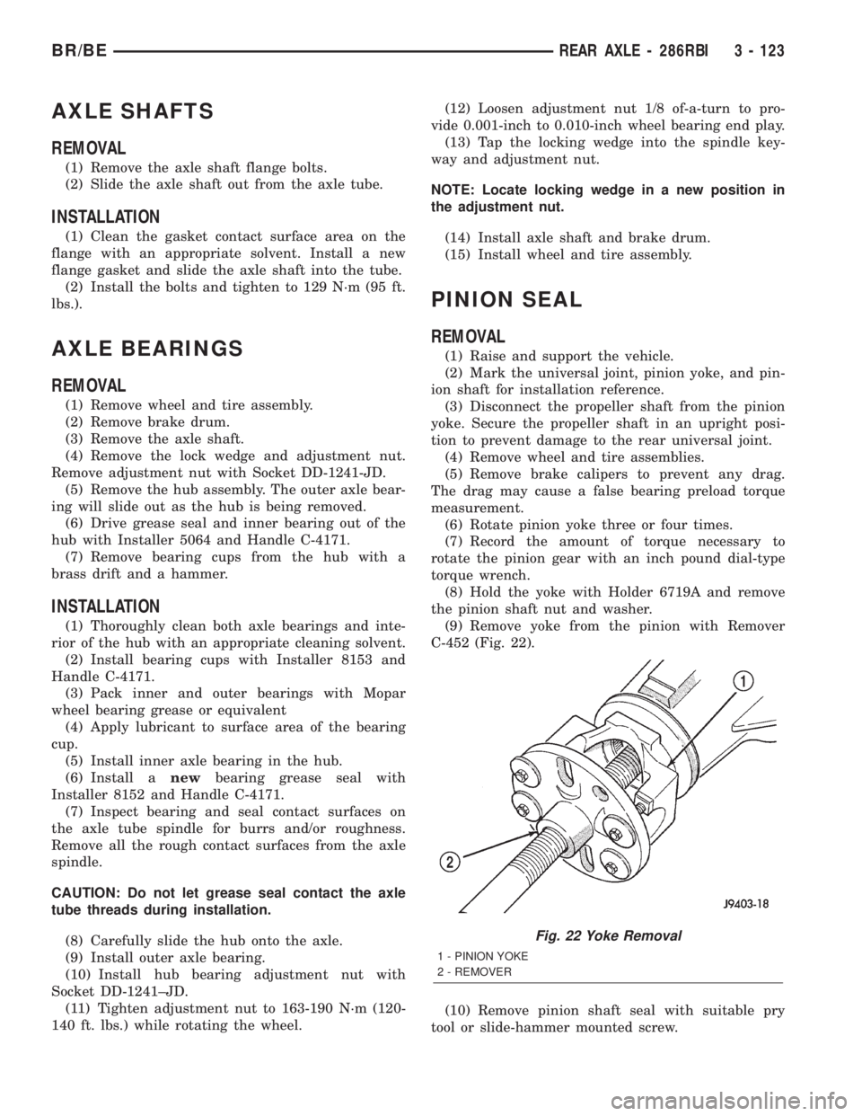
C-452 (Fig. 22).
(10) Remove pinion shaft seal with suitable pry
tool or slide-hammer mounted screw.
Fig. 22 Yoke Removal
1 - PINION YOKE
2 - REMOVER
BR/BEREAR AXLE - 286RBI 3 - 123
Page 180 of 2255

(12) Install wheel and tire assemblies and lower
the vehicle.
DIFFERENTIAL
REMOVAL
(1) Raise and support the vehicle.
(2) Remove fill hole plug from the differential
housing cover.
(3) Remove differential housing cover and drain
lubricant from the housing.
(4) Clean the housing cavity with a flushing oil,
light engine oil or lint free cloth.Do not use water,
steam, kerosene or gasoline for cleaning.
(5) Remove axle shafts.
(6) Note the orientation of the installation refer-
ence letters stamped on the bearing caps and hous-
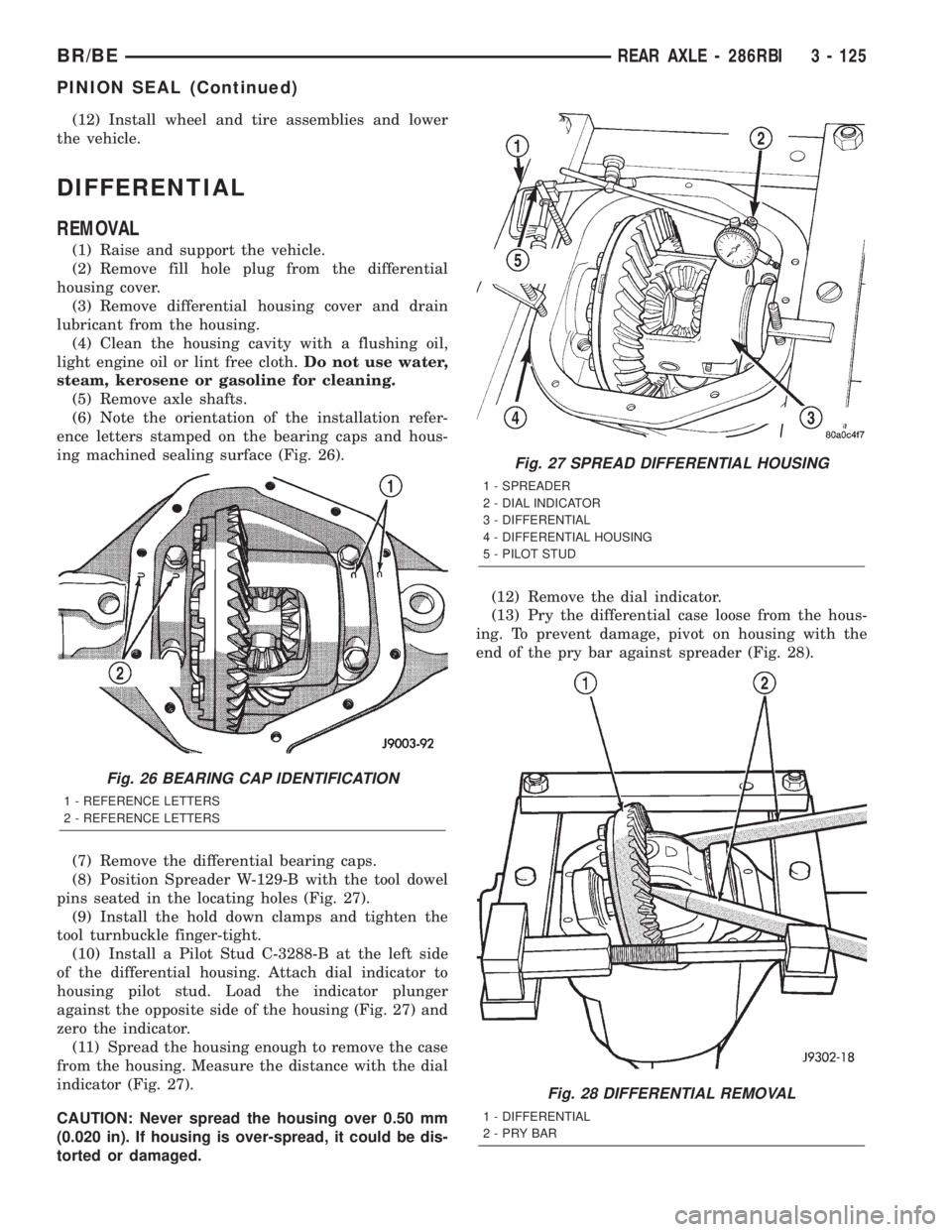
ing machined sealing surface (Fig. 26).
(7) Remove the differential bearing caps.
(8) Position Spreader W-129-B with the tool dowel
pins seated in the locating holes (Fig. 27).
(9) Install the hold down clamps and tighten the
tool turnbuckle finger-tight.
(10) Install a Pilot Stud C-3288-B at the left side
of the differential housing. Attach dial indicator to
housing pilot stud. Load the indicator plunger
against the opposite side of the housing (Fig. 27) and
zero the indicator.
(11) Spread the housing enough to remove the case
from the housing. Measure the distance with the dial
indicator (Fig. 27).
CAUTION: Never spread the housing over 0.50 mm
(0.020 in). If housing is over-spread, it could be dis-
torted or damaged.(12) Remove the dial indicator.
(13) Pry the differential case loose from the hous-
ing. To prevent damage, pivot on housing with the
end of the pry bar against spreader (Fig. 28).
Fig. 26 BEARING CAP IDENTIFICATION
1 - REFERENCE LETTERS
2 - REFERENCE LETTERS
Fig. 27 SPREAD DIFFERENTIAL HOUSING
1 - SPREADER
2 - DIAL INDICATOR
3 - DIFFERENTIAL
4 - DIFFERENTIAL HOUSING
5 - PILOT STUD
Fig. 28 DIFFERENTIAL REMOVAL
1 - DIFFERENTIAL
2-PRYBAR
BR/BEREAR AXLE - 286RBI 3 - 125
PINION SEAL (Continued)
Page 183 of 2255

(12) Fill the differential with Mopar Hypoid Gear
Lubricant or equivalent to bottom of the fill plug
hole.
(13) Install fill hole plug and tighten to 34 N´m (25
ft. lbs.).
(14) Remove support and lower vehicle.
DIFFERENTIAL - TRAC-LOK
DIAGNOSIS AND TESTING - TRAC-LOKT
The most common problem is a chatter noise when
turning corners. Before removing a Trac-lokŸ unit
for repair, drain, flush and refill the axle with the
specified lubricant. A container of Mopar Trac-lokŸ
Lubricant (friction modifier) should be added after
repair service or during a lubricant change.
After changing the lubricant, drive the vehicle and
make 10 to 12 slow, figure-eight turns. This maneu-
ver will pump lubricant through the clutches. This
will correct the condition in most instances. If the
chatter persists, clutch damage could have occurred.
DIFFERENTIAL TEST
The differential can be tested without removing the
differential case by measuring rotating torque. Make
sure brakes are not dragging during this measure-
ment.
(1) Place blocks in front and rear of both front
wheels.
(2) Raise one rear wheel until it is completely off
the ground.
(3) Engine off, transmission in neutral, and park-
ing brake off.
(4) Remove wheel and bolt Special Tool 6790 or
equivalent tool to studs.
(5) Use torque wrench on special tool to rotate
wheel and read rotating torque.
(6) If rotating torque is less than 22 N´m (30 ft.
lbs.) or more than 271 N´m (200 ft. lbs.) on either
wheel the unit should be serviced.
DISASSEMBLY
The Trac-Loktdifferential on this axle has a one-
piece cross shaft and uses one dished disc, regular 5
disc and 7 plates.
NOTE: Pay attention to the clutch pack arrangement
during disassembly. Note the direction of the con-
cave and convex side of the plates and discs.
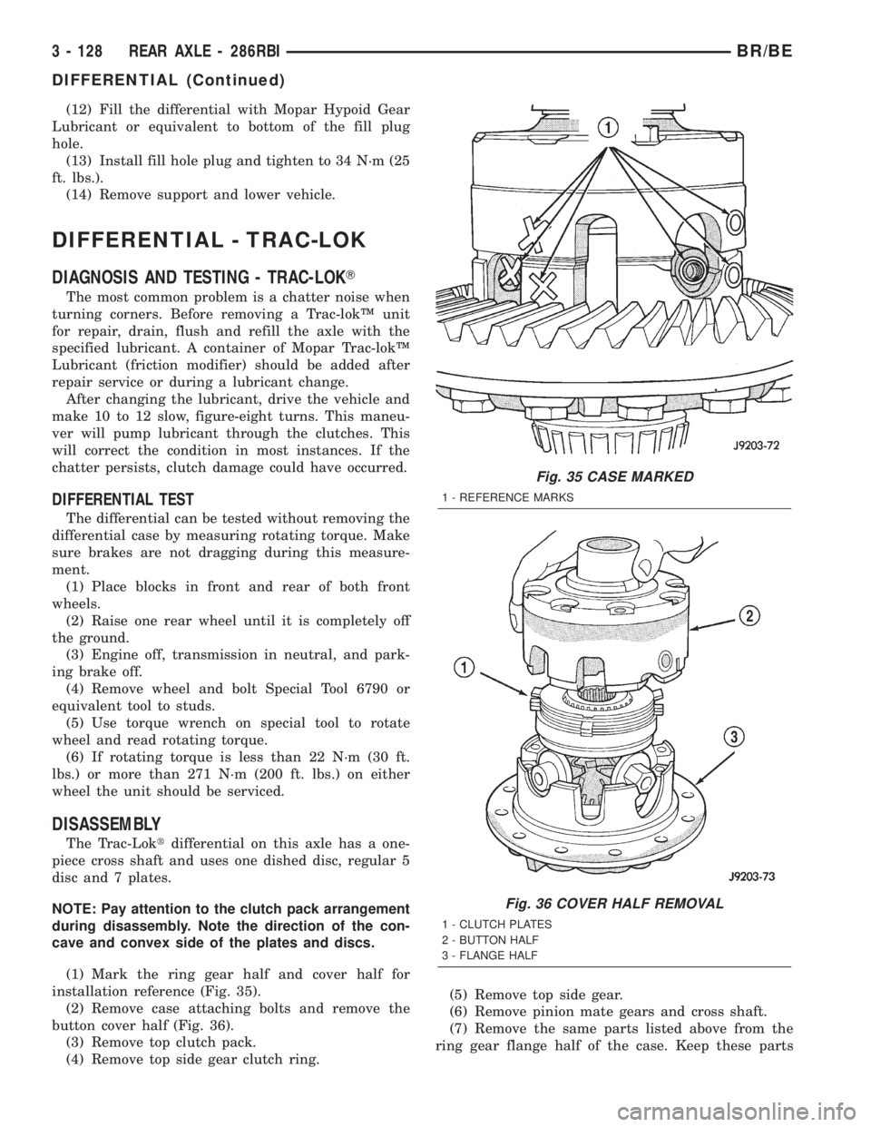
(1) Mark the ring gear half and cover half for
installation reference (Fig. 35).
(2) Remove case attaching bolts and remove the
button cover half (Fig. 36).
(3) Remove top clutch pack.
(4) Remove top side gear clutch ring.(5) Remove top side gear.
(6) Remove pinion mate gears and cross shaft.
(7) Remove the same parts listed above from the
ring gear flange half of the case. Keep these parts
Fig. 35 CASE MARKED
1 - REFERENCE MARKS
Fig. 36 COVER HALF REMOVAL
1 - CLUTCH PLATES
2 - BUTTON HALF
3 - FLANGE HALF
3 - 128 REAR AXLE - 286RBIBR/BE
DIFFERENTIAL (Continued)
Page 193 of 2255

SPECIAL TOOLS
BASE BRAKESHYDRAULIC/MECHANICAL
DESCRIPTION
This vehicle is equipped with front disc brakes and
rear drum brakes also certain vehicles have four
wheel disc brakes. The front and rear disc brakes
consist of dual piston calipers and ventilated rotors.
The rear brakes are dual brake shoe, internal
expanding units with cast brake drums. The parking
brake mechanism is cable operated and connected to
the rear brake trailing shoes. Power brake assist is
standard equipment. A vacuum operated power brake
booster is used on gas engine vehicles. A hydraulic
booster is used on diesel engine vehicles.
Two antilock brake systems are used on this vehi-
cle. A rear wheel antilock (RWAL) brake system and
all-wheel antilock brake system (ABS). The RWAL
and ABS systems are designed to retard wheel
lockup while braking. Retarding wheel lockup is
accomplished by modulating fluid pressure to the
wheel brake units. Both systems are monitored by a
microprocessor which controls the operation of the
systems.
WARNING
WARNING: DUST AND DIRT ACCUMULATING ON
BRAKE PARTS DURING NORMAL USE MAY CON-
TAIN ASBESTOS FIBERS FROM PRODUCTION OR
AFTERMARKET LININGS. BREATHING EXCESSIVE
CONCENTRATIONS OF ASBESTOS FIBERS CAN
CAUSE SERIOUS BODILY HARM. EXERCISE CARE
WHEN SERVICING BRAKE PARTS. DO NOT CLEAN
BRAKE PARTS WITH COMPRESSED AIR OR BY
DRY BRUSHING. USE A VACUUM CLEANER SPE-
CIFICALLY DESIGNED FOR THE REMOVAL OF
ASBESTOS FIBERS FROM BRAKE COMPONENTS.
IF A SUITABLE VACUUM CLEANER IS NOT AVAIL-
ABLE, CLEANING SHOULD BE DONE WITH A
WATER DAMPENED CLOTH. DO NOT SAND, OR
GRIND BRAKE LINING UNLESS EQUIPMENT USED
IS DESIGNED TO CONTAIN THE DUST RESIDUE.
DISPOSE OF ALL RESIDUE CONTAINING ASBES-
TOS FIBERS IN SEALED BAGS OR CONTAINERS
TO MINIMIZE EXPOSURE TO YOURSELF AND OTH-
ERS. FOLLOW PRACTICES PRESCRIBED BY THE
OCCUPATIONAL SAFETY AND HEALTH ADMINIS-
TRATION AND THE ENVIRONMENTAL PROTECTION
AGENCY FOR THE HANDLING, PROCESSING, AND
DISPOSITION OF DUST OR DEBRIS THAT MAY
CONTAIN ASBESTOS FIBERS.
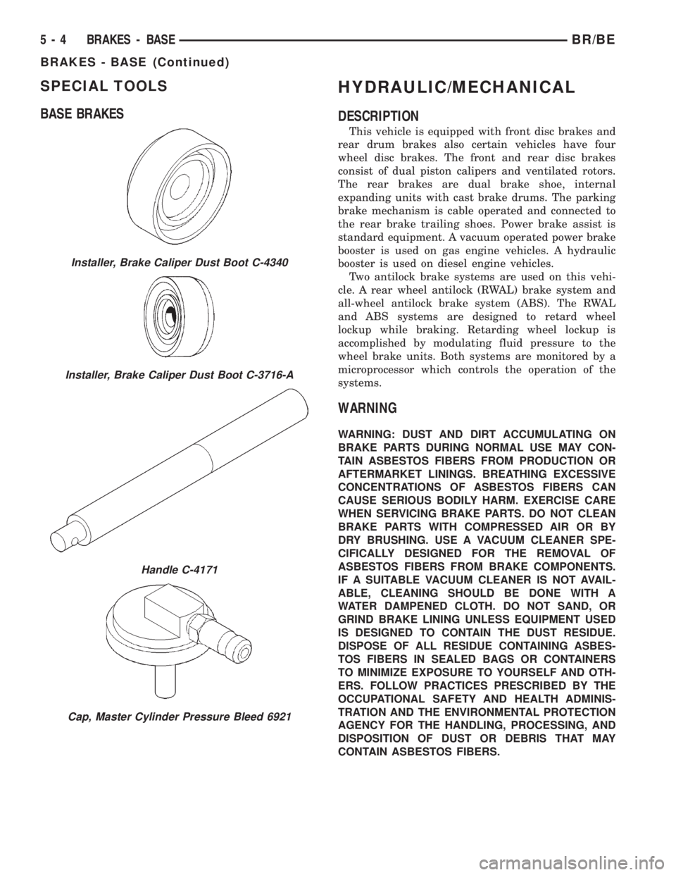
Installer, Brake Caliper Dust Boot C-4340
Installer, Brake Caliper Dust Boot C-3716-A
Handle C-4171
Cap, Master Cylinder Pressure Bleed 6921
5 - 4 BRAKES - BASEBR/BE
BRAKES - BASE (Continued)