2002 DODGE RAM wheel
[x] Cancel search: wheelPage 207 of 2255
EXTERIOR/BRAKE LAMP SWITCH - INSTALLA-
TION).
(10) Install knee bolster, (Refer to 23 - BODY/IN-
STRUMENT PANEL/STEERING COLUMN OPEN-
ING COVER - INSTALLATION).
POWER BRAKE BOOSTER
DIAGNOSIS AND TESTING - HYDRAULIC
BOOSTER
The hydraulic booster uses hydraulic pressure from
the power steering pump. Before diagnosing a
booster problem, first verify the power steering pump
is operating properly. Perform the following checks.
²Check the power steering fluid level.
²Check the brake fluid level.
²Check all power steering hoses and lines for
leaks and restrictions.
²Check power steering pump pressure.
NOISES
The hydraulic booster unit will produce certain
characteristic booster noises. The noises may occur
when the brake pedal is used in a manner not asso-
ciated with normal braking or driving habits.
HISSING
A hissing noise may be noticed when above normal
brake pedal pressure is applied, 40 lbs. or above. The
noise will be more noticeable if the vehicle is not
moving. The noise will increase with the brake pedal
pressure and an increase of system operating temper-
ature.
CLUNK-CHATTER-CLICKING
A clunk-chatter-clicking may be noticed when the
brake pedal is released quickly, after above normal
brake pedal pressure is applied 50-100 lbs..
BOOSTER FUNCTION TEST
With the engine off depress the brake pedal several
times to discharge the accumulator. Then depress the
brake pedal using 40 lbs. of force and start the
engine. The brake pedal should fall and then push
back against your foot. This indicates the booster is
operating properly.
ACCUMULATOR LEAKDOWN
(1) Start the engine, apply the brakes and turn the
steering wheel from lock to lock. This will ensure the
accumulator is charged. Turn off the engine and let
the vehicle sit for one hour. After one hour there
should be at least two power assisted brake applica-
tion with the engine off. If the system does not retain
a charge the booster must be replaced.(2) With the engine off depress the brake pedal
several times to discharge the accumulator. Grasp
the accumulator and see if it wobbles or turns. If it
does the accumulator has lost a gas charge and the
booster must be replaced.
SEAL LEAKAGE
If the booster leaks from any of the seals the
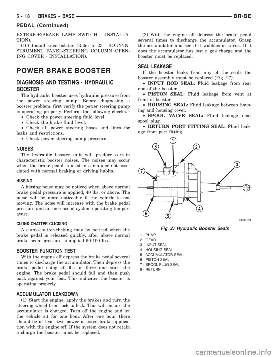
booster assembly must be replaced (Fig. 27).
²INPUT ROD SEAL:Fluid leakage from rear
end of the booster.
²PISTON SEAL:Fluid leakage from vent at
front of booster.
²HOUSING SEAL:Fluid leakage between hous-
ing and housing cover.
²SPOOL VALVE SEAL:Fluid leakage near
spool plug.
²RETURN PORT FITTING SEAL:Fluid leak-
age from port fitting.
Fig. 27 Hydraulic Booster Seals
1 - PUMP
2 - GEAR
3 - INPUT SEAL
4 - HOUSING SEAL
5 - ACCUMULATOR SEAL
6 - PISTON SEAL
7 - SPOOL PLUG SEAL
8 - RETURN
5 - 18 BRAKES - BASEBR/BE
PEDAL (Continued)
Page 208 of 2255
HYDRAULIC BOOSTER DIAGNOSIS CHART
CONDITION POSSIBLE CAUSES CORRECTION
Slow Brake Pedal Return 1. Excessive seal friction in booster. 1. Replace booster.
2. Faulty spool valve action. 2. Replace booster.
3. Restriction in booster return hose. 3. Replace hose.
4. Damaged input rod. 4. Replace booster.
Excessive Brake Pedal
Effort.1. Internal or external seal leakage. 1. Replace booster.
2. Faulty steering pump. 2. Replace pump.
Brakes Self Apply 1. Dump valve faulty. 1. Replace booster.
2. Contamination in hydraulic
system.2. Flush hydraulic system and replace
booster.
3. Restriction in booster return hose. 3. Replace hose.
Booster Chatter, Pedal
Vibration1. Slipping pump belt. 1. Replace power steering belt.
2. Low pump fluid level. 2. Fill pump and check for leaks.
Grabbing Brakes 1. Low pump flow. 1. Test and repair/replace pump.
2. Faulty spool valve action. 2. Replace booster.
STANDARD PROCEDURE - BLEEDING
The hydraulic booster is generally self-bleeding,
this procedure will normally bleed the air from the
booster. Normal driving and operation of the unit will
remove any remaining trapped air.
(1) Fill power steering pump reservoir.
(2) Disconnect fuel shutdown relay and crank the
engine for several seconds, Refer to Fuel System for
relay location and WARNING.
(3) Check fluid level and add if necessary.
(4) Connect fuel shutdown relay and start the
engine.
(5) Turn the steering wheel slowly from lock to
lock twice.
(6) Stop the engine and discharge the accumulator
by depressing the brake pedal 5 times.
(7) Start the engine and turn the steering wheel
slowly from lock to lock twice.
(8) Turn off the engine and check fluid level and
add if necessary.
NOTE: If fluid foaming occurs, wait for foam to dis-
sipate and repeat steps 7 and 8.
REMOVAL
NOTE: If the booster is being replaced because the
power steering fluid is contaminated, flush the
power steering system before replacing the booster.(1) With engine off depress the brake pedal 5
times to discharge the accumulator.
(2) Remove brake lines from master cylinder.
(3) Remove mounting nuts from the master cylin-
der.
(4) Remove the bracket from the hydraulic booster
lines and master cylinder mounting studs.
(5) Remove the master cylinder.
(6) Remove the return hose and the two pressure
lines from the hydraulic booster (Fig. 28).
(7) Remove the booster push rod clip, washer and
rod remove from the brake pedal. (Fig. 29).
(8) Remove the mounting nuts from the hydraulic
booster and remove the booster (Fig. 30).
INSTALLATION
(1) Install the hydraulic booster and tighten the
mounting nuts to 28 N´m (21 ft. lbs.).
(2) Install the booster push rod, washer and clip
onto the brake pedal.
(3) Install the master cylinder on the mounting
studs. and tighten the mounting nuts to 23 N´m (17
ft. lbs.).
(4) Install the brake lines to the master cylinder
and tighten to 19-200 N´m (170-200 in. lbs.).
(5) Install the hydraulic booster line bracket onto
the master cylinder mounting studs.
(6) Install the master cylinder mounting nuts and
tighten to 23 N´m (17 ft. lbs.).
BR/BEBRAKES - BASE 5 - 19
POWER BRAKE BOOSTER (Continued)
Page 210 of 2255
ROTOR MINIMUM THICKNESS
Measure rotor thickness at the center of the brake
shoe contact surface. Replace the rotor if below min-
imum thickness, or if machining would reduce thick-
ness below the allowable minimum.
Rotor minimum thickness is usually specified on
the rotor hub. The specification is either stamped or
cast into the hub surface.
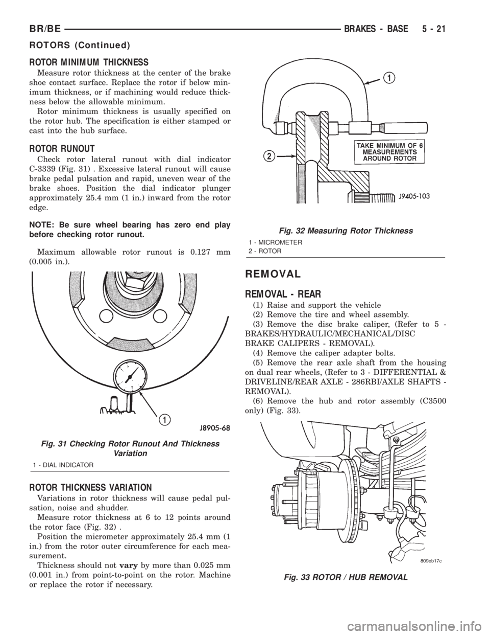
ROTOR RUNOUT
Check rotor lateral runout with dial indicator
C-3339 (Fig. 31) . Excessive lateral runout will cause
brake pedal pulsation and rapid, uneven wear of the
brake shoes. Position the dial indicator plunger
approximately 25.4 mm (1 in.) inward from the rotor
edge.
NOTE: Be sure wheel bearing has zero end play
before checking rotor runout.
Maximum allowable rotor runout is 0.127 mm
(0.005 in.).
ROTOR THICKNESS VARIATION
Variations in rotor thickness will cause pedal pul-
sation, noise and shudder.
Measure rotor thickness at 6 to 12 points around
the rotor face (Fig. 32) .
Position the micrometer approximately 25.4 mm (1
in.) from the rotor outer circumference for each mea-
surement.
Thickness should notvaryby more than 0.025 mm
(0.001 in.) from point-to-point on the rotor. Machine
or replace the rotor if necessary.
REMOVAL
REMOVAL - REAR
(1) Raise and support the vehicle
(2) Remove the tire and wheel assembly.
(3) Remove the disc brake caliper, (Refer to 5 -
BRAKES/HYDRAULIC/MECHANICAL/DISC
BRAKE CALIPERS - REMOVAL).
(4) Remove the caliper adapter bolts.
(5) Remove the rear axle shaft from the housing
on dual rear wheels, (Refer to 3 - DIFFERENTIAL &
DRIVELINE/REAR AXLE - 286RBI/AXLE SHAFTS -
REMOVAL).
(6) Remove the hub and rotor assembly (C3500
only) (Fig. 33).
Fig. 31 Checking Rotor Runout And Thickness
Variation
1 - DIAL INDICATOR
Fig. 32 Measuring Rotor Thickness
1 - MICROMETER
2 - ROTOR
Fig. 33 ROTOR / HUB REMOVAL
BR/BEBRAKES - BASE 5 - 21
ROTORS (Continued)
Page 211 of 2255
REMOVAL - FRONT ± 2500
(1) Raise and support the vehicle.
(2) Remove the wheel and tire assembly.
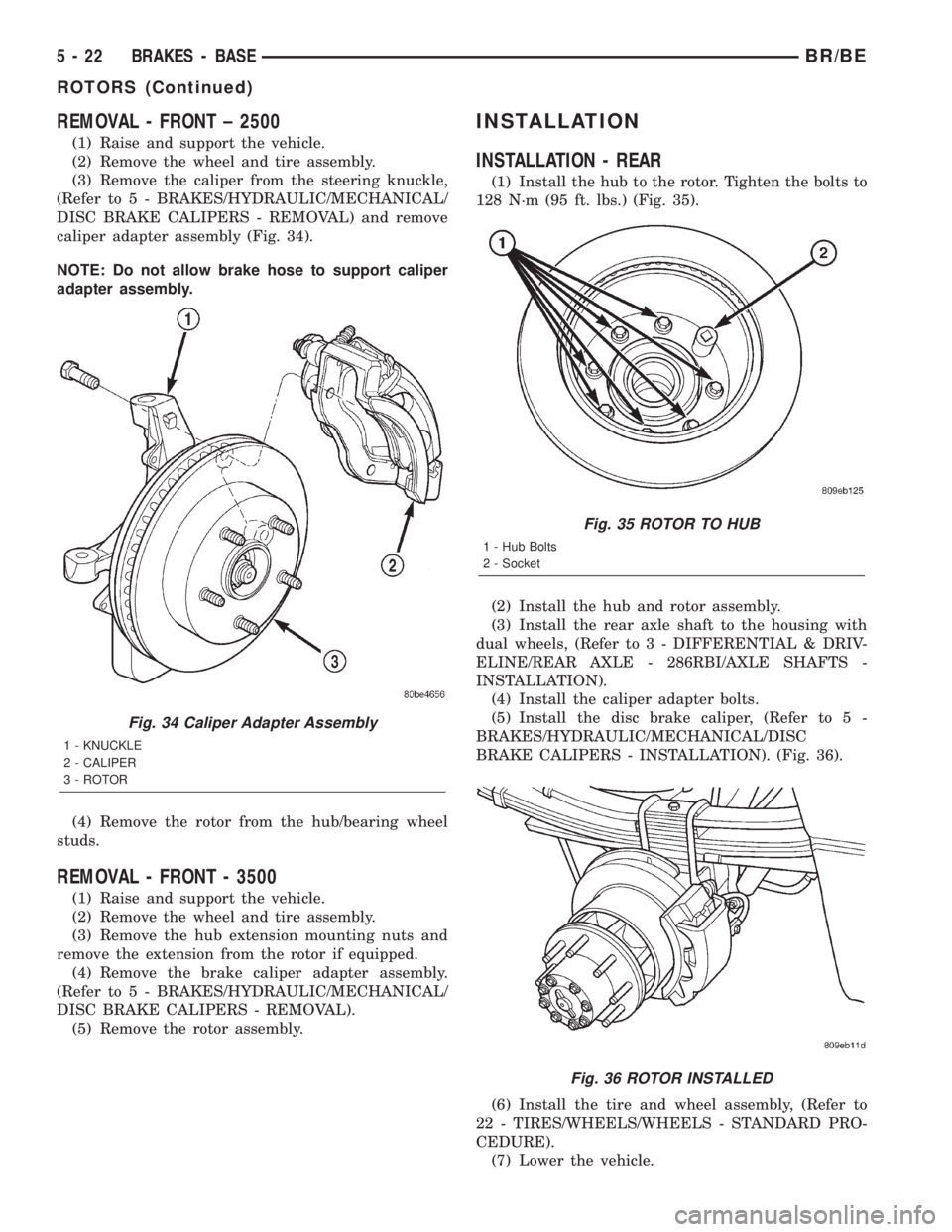
(3) Remove the caliper from the steering knuckle,
(Refer to 5 - BRAKES/HYDRAULIC/MECHANICAL/
DISC BRAKE CALIPERS - REMOVAL) and remove
caliper adapter assembly (Fig. 34).
NOTE: Do not allow brake hose to support caliper
adapter assembly.
(4) Remove the rotor from the hub/bearing wheel
studs.
REMOVAL - FRONT - 3500
(1) Raise and support the vehicle.
(2) Remove the wheel and tire assembly.
(3) Remove the hub extension mounting nuts and
remove the extension from the rotor if equipped.
(4) Remove the brake caliper adapter assembly.
(Refer to 5 - BRAKES/HYDRAULIC/MECHANICAL/
DISC BRAKE CALIPERS - REMOVAL).
(5) Remove the rotor assembly.
INSTALLATION
INSTALLATION - REAR
(1) Install the hub to the rotor. Tighten the bolts to
128 N´m (95 ft. lbs.) (Fig. 35).
(2) Install the hub and rotor assembly.
(3) Install the rear axle shaft to the housing with
dual wheels, (Refer to 3 - DIFFERENTIAL & DRIV-
ELINE/REAR AXLE - 286RBI/AXLE SHAFTS -
INSTALLATION).
(4) Install the caliper adapter bolts.
(5) Install the disc brake caliper, (Refer to 5 -
BRAKES/HYDRAULIC/MECHANICAL/DISC
BRAKE CALIPERS - INSTALLATION). (Fig. 36).
(6) Install the tire and wheel assembly, (Refer to
22 - TIRES/WHEELS/WHEELS - STANDARD PRO-
CEDURE).
(7) Lower the vehicle.
Fig. 34 Caliper Adapter Assembly
1 - KNUCKLE
2 - CALIPER
3 - ROTOR
Fig. 35 ROTOR TO HUB
1 - Hub Bolts
2 - Socket
Fig. 36 ROTOR INSTALLED
5 - 22 BRAKES - BASEBR/BE
ROTORS (Continued)
Page 212 of 2255
INSTALLATION - FRONT ± 2500
(1) On models with all-wheel antilock system
(ABS), check condition of tone wheel on hub/bearing.
If teeth on wheel are damaged, hub/bearing assembly
will have to be replaced (tone wheel is not serviced
separately).
(2) Install rotor onto the hub/bearing wheel studs.
(3) Install the caliper adapter assembly,(Refer to 5
- BRAKES/HYDRAULIC/MECHANICAL/DISC
BRAKE CALIPERS - INSTALLATION) and tighten
adapter bolts to:
²LD 1500: 176 N´m (130 ft lbs.)
²HD 2500: 285 N´m (210 ft lbs.)
(4) Install the wheel and tire assembly, (Refer to
22 - TIRES/WHEELS/WHEELS - STANDARD PRO-
CEDURE) and lower vehicle.
(5) Apply brakes several times to seat brake shoes.
Be sure to obtain firm pedal before moving vehicle.
INSTALLATION - FRONT - 3500
(1) Position the rotor on the hub/bearing.
(2) Install the brake caliper adapter assembly
(Refer to 5 - BRAKES/HYDRAULIC/MECHANICAL/
DISC BRAKE CALIPERS - INSTALLATION) and
tighten adapter bolts to 285 N´m (210 ft. lbs).
(3) Install the wheel and tire assemblies, (Refer to
22 - TIRES/WHEELS/WHEELS - STANDARD PRO-
CEDURE).
(4) Remove the support and lower the vehicle.
(5) Apply brakes several times to seat brake shoes
and caliper piston. Do not move vehicle until firm
brake pedal is obtained.
BRAKE PADS/SHOES
REMOVAL
REMOVAL - REAR
(1) Raise and support the vehicle.
(2) Remove the rear wheel and tire assemblies.
(3) Compress the caliper.
(4) Remove caliper mounting bolts
NOTE: Do not allow brake hose to support caliper
assembly.
(5) Remove the caliper, (Refer to 5 - BRAKES/HY-
DRAULIC/MECHANICAL/DISC BRAKE CALIPERS
- REMOVAL) and then tilt the top up and off the cal-
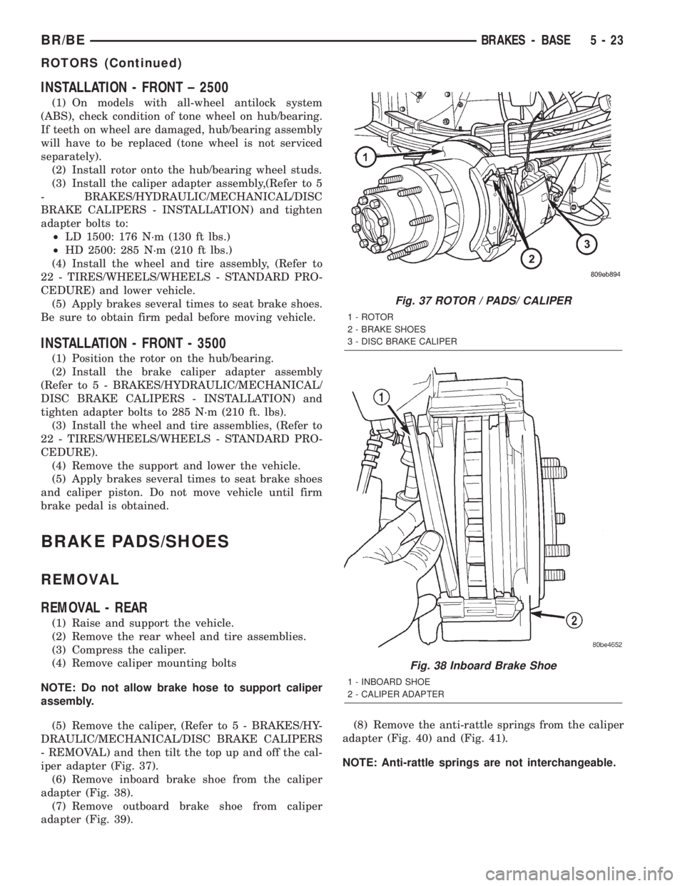
iper adapter (Fig. 37).
(6) Remove inboard brake shoe from the caliper
adapter (Fig. 38).
(7) Remove outboard brake shoe from caliper
adapter (Fig. 39).(8) Remove the anti-rattle springs from the caliper
adapter (Fig. 40) and (Fig. 41).
NOTE: Anti-rattle springs are not interchangeable.
Fig. 37 ROTOR / PADS/ CALIPER
1 - ROTOR
2 - BRAKE SHOES
3 - DISC BRAKE CALIPER
Fig. 38 Inboard Brake Shoe
1 - INBOARD SHOE
2 - CALIPER ADAPTER
BR/BEBRAKES - BASE 5 - 23
ROTORS (Continued)
Page 213 of 2255

REMOVAL - FRONT
(1) Raise and support vehicle.
(2) Remove front wheel and tire assemblies.
(3) Compress caliper.
(4) Remove caliper, (Refer to 5 - BRAKES/HY-
DRAULIC/MECHANICAL/DISC BRAKE CALIPERS
- REMOVAL).
(5) Remove caliper by tilting the top up and off the
caliper adapter (Fig. 42).NOTE: Do not allow brake hose to support caliper
assembly.
(6) Remove inboard brake shoe from the caliper
adapter (Fig. 43).
(7) Remove outboard brake shoe from caliper
adapter (Fig. 44).
(8) Remove the anti-rattle springs from the caliper
adapter (Fig. 45) and (Fig. 46).
NOTE: Anti-rattle springs are not interchangeable.
Fig. 39 Outboard Brake Shoe
1 - OUTBOARD SHOE
2 - CALIPER ADAPTER
Fig. 40 Top Anti-Rattle Spring
1 - CALIPER ADAPTER
2 - ANTI-RATTLE SPRING
Fig. 41 Bottom Anti-Rattle Spring
1 - ANTI-RATTLE SPRING
2 - CALIPER ADAPTER
Fig. 42 Caliper
1 - CALIPER
2 - CALIPER ADAPTER
5 - 24 BRAKES - BASEBR/BE
BRAKE PADS/SHOES (Continued)
Page 215 of 2255
(7) Install caliper, (Refer to 5 - BRAKES/HY-
DRAULIC/MECHANICAL/DISC BRAKE CALIPERS
- INSTALLATION) (Refer to 5 - BRAKES/HYDRAU-
LIC/MECHANICAL/DISC BRAKE CALIPERS -
INSTALLATION).
(8) Install wheel and tire assemblies and lower
vehicle, (Refer to 22 - TIRES/WHEELS/WHEELS -
STANDARD PROCEDURE).
(9) Apply brakes several times to seat caliper pis-
tons and brake shoes and obtain firm pedal.
(10) Top off master cylinder fluid level.
INSTALLATION - FRONT
(1) Bottom pistons in caliper bore with C-clamp.
Place an old brake shoe between a C-clamp and cal-
iper piston.
(2) Clean caliper mounting adapter and anti-rattle
springs.
(3) Lubricate anti-rattle springs with Mopar brake
grease.
(4) Install anti-rattle springs.
NOTE: Anti-rattle springs are not interchangeable.
(5) Install inboard brake shoe in adapter.
(6) Install outboard brake shoe in adapter.
(7) Tilt the bottom of the caliper over rotor and
under adapter. Then push the top of the caliper down
onto the adapter.
(8) Install caliper, (Refer to 5 - BRAKES/HY-
DRAULIC/MECHANICAL/DISC BRAKE CALIPERS
- INSTALLATION).
(9) Install wheel and tire assemblies and lower
vehicle, (Refer to 22 - TIRES/WHEELS/WHEELS -
STANDARD PROCEDURE).
(10) Apply brakes several times to seat caliper pis-
tons and brake shoes and obtain firm pedal.
(11) Top off master cylinder fluid level.
MASTER CYLINDER
DESCRIPTION
A two-piece master cylinder is used on all models.
The cylinder body containing the primary and sec-
ondary pistons is made of aluminum. The removable
fluid reservoir is made of nylon reinforced with glass
fiber. The reservoir stores reserve brake fluid for the
hydraulic brake circuits. The reservoir is the only
serviceable component.
The fluid compartments of the nylon reservoir are
interconnected to permit fluid level equalization.
However, the equalization feature does not affect cir-
cuit separation in the event of a front or rear brake
malfunction. The reservoir compartments will retain
enough fluid to operate the functioning hydraulic cir-
cuit.Care must be exercised when removing/installing
the master cylinder connecting lines. The threads in
the cylinder fluid ports can be damaged if care is not
exercised. Start all brake line fittings by hand to
avoid cross threading.
The cylinder reservoir can be replaced when neces-
sary. However, the aluminum body section of the
master cylinder is not a repairable component.
NOTE: If diagnosis indicates that an internal mal-
function has occurred, the aluminum body section
must be replaced as an assembly.
OPERATION
The master cylinder bore contains a primary and
secondary piston. The primary piston supplies
hydraulic pressure to the front brakes. The secondary
piston supplies hydraulic pressure to the rear brakes.
DIAGNOSIS AND TESTING - MASTER
CYLINDER/POWER BOOSTER
(1) Start engine and check booster vacuum hose
connections. A hissing noise indicates vacuum leak.
Correct any vacuum leak before proceeding.
(2) Stop engine and shift transmission into Neu-
tral.
(3) Pump brake pedal until all vacuum reserve in
booster is depleted.
(4) Press and hold brake pedal under light foot
pressure. The pedal should hold firm, if the pedal
falls away master cylinder is faulty (internal leak-
age).
(5) Start engine and note pedal action. It should
fall away slightly under light foot pressure then hold
firm. If no pedal action is discernible, power booster,
vacuum supply, or vacuum check valve is faulty. Pro-
ceed to the POWER BOOSTER VACUUM TEST.
(6) If the POWER BOOSTER VACUUM TEST
passes, rebuild booster vacuum reserve as follows:
Release brake pedal. Increase engine speed to 1500
rpm, close the throttle and immediately turn off igni-
tion to stop engine.
(7) Wait a minimum of 90 seconds and try brake
action again. Booster should provide two or more vac-
uum assisted pedal applications. If vacuum assist is
not provided, booster is faulty.
POWER BOOSTER VACUUM TEST
(1) Connect vacuum gauge to booster check valve
with short length of hose and T-fitting (Fig. 47).
(2) Start and run engine at curb idle speed for one
minute.
(3) Observe the vacuum supply. If vacuum supply
is not adequate, repair vacuum supply.
5 - 26 BRAKES - BASEBR/BE
BRAKE PADS/SHOES (Continued)
Page 219 of 2255

(3) Remove the front cable from the cable connec-
tor.
(4) Compress cable end fitting at underbody
bracket and remove the cable from the bracket.
(5) Lower vehicle.
(6) Push ball end of cable out of pedal clevis with
small screwdriver.
(7) Compress cable end fitting at the pedal bracket
and remove the cable (Fig. 55).
(8) Remove the left cowl trim and sill plate.
(9) Pull up the carpet and remove the cable from
the body clip.
(10) Pull up on the cable and remove the cable
with the body grommet.
INSTALLATION
INSTALLATION - REAR PARK BRAKE CABLE
(1) Push each cable end through the brake cable
support plate hole until the cable end fitting tabs
lock into place.
NOTE: Pull on the cable to ensure it is locked into
place.
(2) Push the cable through the frame bracket.
(3) Lock the left cable end fitting tabs into the
frame bracket hole.
(4) Install the rear cables into the tensioner rod
behind the rear of the brake assembly.(5) Install the cable to the intermediate cable con-
nector.
(6) Release and remove the lock out device.
(7) Perform the park brake adjustment procedure,
(Refer to 5 - BRAKES/PARKING BRAKE/CABLE
TENSIONER - ADJUSTMENTS).
(8) Remove the supports and lower the vehicle.
INSTALLATION - FRONT PARKING BRAKE
CABLE
(1) From inside the vehicle, insert the cable end
fitting into the hole in the pedal assembly.
(2) Seat the cable retainer in the pedal assembly.
(3) Engage the cable ball end in clevis on the pedal
assembly.
(4) Route the cable along the top of the wheel well
and clip in place.
(5) Route the cable through the floorpan and
install the body grommet.
(6) Place the carpet down and install the left cowl
trim and sill plate.
(7) Raise and support the vehicle.
(8) Route the cable through the underbody bracket
and seat the cable housing retainer in the bracket.
(9) Connect the cable to the cable connector.
(10) Perform the park brake adjustment proce-
dure, (Refer to 5 - BRAKES/PARKING BRAKE/CA-
BLE TENSIONER - ADJUSTMENTS).
(11) Lower the vehicle.
CABLE TENSIONER
ADJUSTMENTS
ADJUSTMENT
NOTE: Tensioner adjustment is only necessary
when the tensioner, or a cable has been replaced or
disconnected for service. When adjustment is nec-
essary, perform adjustment only as described in the
following procedure. This is necessary to avoid
faulty park brake operation.
(1) Raise the vehicle.
(2) Back off the cable tensioner adjusting nut to
create slack in the cables.
(3) Remove the rear wheel/tire assemblies. Then
remove the brake drum in hat assembly.
(4) Verify the brakes are in good condition and
operating properly.
(5) Verify the park brake cables operate freely and
are not binding, or seized.
(6) Check the rear brake shoe adjustment with
standard brake gauge.
Fig. 55 Parking Brake Pedal
1 - PARK BRAKE PEDAL
2 - FRONT CABLE
5 - 30 BRAKES - BASEBR/BE
CABLES (Continued)