2002 DODGE RAM wheel
[x] Cancel search: wheelPage 228 of 2255
REMOVAL
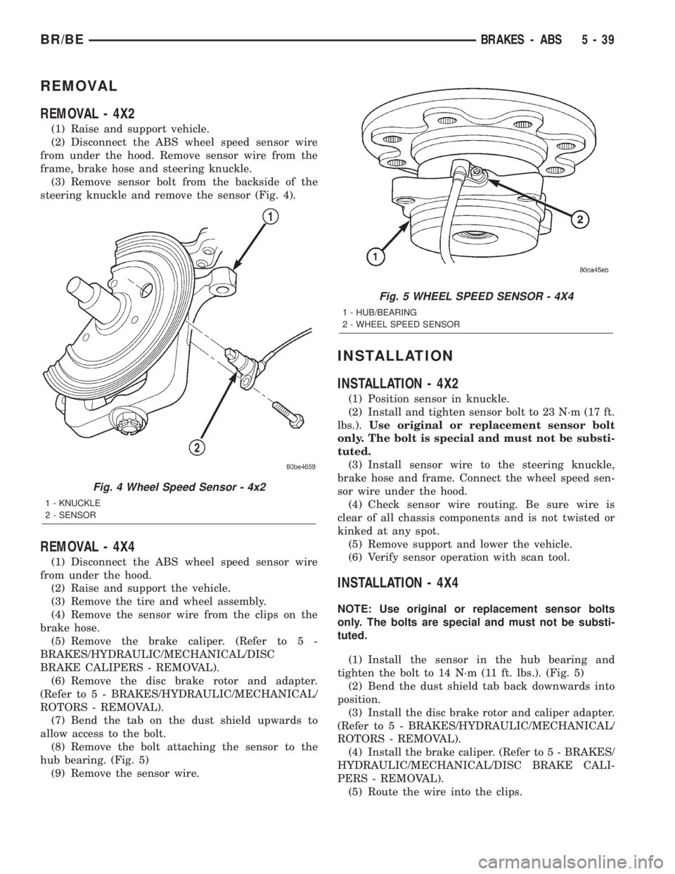
REMOVAL - 4X2
(1) Raise and support vehicle.
(2) Disconnect the ABS wheel speed sensor wire
from under the hood. Remove sensor wire from the
frame, brake hose and steering knuckle.
(3) Remove sensor bolt from the backside of the
steering knuckle and remove the sensor (Fig. 4).
REMOVAL - 4X4
(1) Disconnect the ABS wheel speed sensor wire
from under the hood.
(2) Raise and support the vehicle.
(3) Remove the tire and wheel assembly.
(4) Remove the sensor wire from the clips on the
brake hose.
(5) Remove the brake caliper. (Refer to 5 -
BRAKES/HYDRAULIC/MECHANICAL/DISC
BRAKE CALIPERS - REMOVAL).
(6) Remove the disc brake rotor and adapter.
(Refer to 5 - BRAKES/HYDRAULIC/MECHANICAL/
ROTORS - REMOVAL).
(7) Bend the tab on the dust shield upwards to
allow access to the bolt.
(8) Remove the bolt attaching the sensor to the
hub bearing. (Fig. 5)
(9) Remove the sensor wire.
INSTALLATION
INSTALLATION - 4X2
(1) Position sensor in knuckle.
(2) Install and tighten sensor bolt to 23 N´m (17 ft.
lbs.).Use original or replacement sensor bolt
only. The bolt is special and must not be substi-
tuted.
(3) Install sensor wire to the steering knuckle,
brake hose and frame. Connect the wheel speed sen-
sor wire under the hood.
(4) Check sensor wire routing. Be sure wire is
clear of all chassis components and is not twisted or
kinked at any spot.
(5) Remove support and lower the vehicle.
(6) Verify sensor operation with scan tool.
INSTALLATION - 4X4
NOTE: Use original or replacement sensor bolts
only. The bolts are special and must not be substi-
tuted.
(1) Install the sensor in the hub bearing and
tighten the bolt to 14 N´m (11 ft. lbs.). (Fig. 5)
(2) Bend the dust shield tab back downwards into
position.
(3) Install the disc brake rotor and caliper adapter.
(Refer to 5 - BRAKES/HYDRAULIC/MECHANICAL/
ROTORS - REMOVAL).
(4) Install the brake caliper. (Refer to 5 - BRAKES/
HYDRAULIC/MECHANICAL/DISC BRAKE CALI-
PERS - REMOVAL).
(5) Route the wire into the clips.
Fig. 4 Wheel Speed Sensor - 4x2
1 - KNUCKLE
2 - SENSOR
Fig. 5 WHEEL SPEED SENSOR - 4X4
1 - HUB/BEARING
2 - WHEEL SPEED SENSOR
BR/BEBRAKES - ABS 5 - 39
Page 229 of 2255
NOTE: Check the sensor wire routing. Be sure the
wire is clear of all chassis components and is not
twisted or kinked at any spot.
(6) Install the tire and wheel assembly.
(7) Remove the support and lower the vehicle.
(8) Reconnect the ABS wheel speed sensor wire
electrical connector inside the engine compartment.
(9) Apply the brakes several times to seat the
brake shoes and caliper piston. Do not move the vehi-
cle until a firm brake pedal is obtained.
(10) Verify the wheel speed sensor operation with
a scan tool.
REAR WHEEL SPEED SENSOR
DIAGNOSIS AND TESTING - REAR WHEEL
SPEED SENSOR
Diagnosis of base brake conditions which are
mechanical in nature should be performed first. This
includes brake noise, lack of power assist, parking
brake, or vehicle vibration during normal braking.
The Antilock brake system performs several self-
tests every time the ignition switch is turned on and
the vehicle is driven. The CAB monitors the system
inputs and outputs circuits to verify the system is
operating properly. If the CAB senses a malfunction
in the system it will set a DTC into memory and trig-
ger the warning lamp.
NOTE: The MDS or DRB III scan tool is used to
diagnose the Antilock Brake system. For test proce-
dures refer to the Chassis Diagnostic Manual.
REMOVAL
(1) Raise vehicle on hoist.
(2) Remove brake line mounting nut and remove
the brake line from the sensor stud.
(3) Remove mounting stud from the sensor and
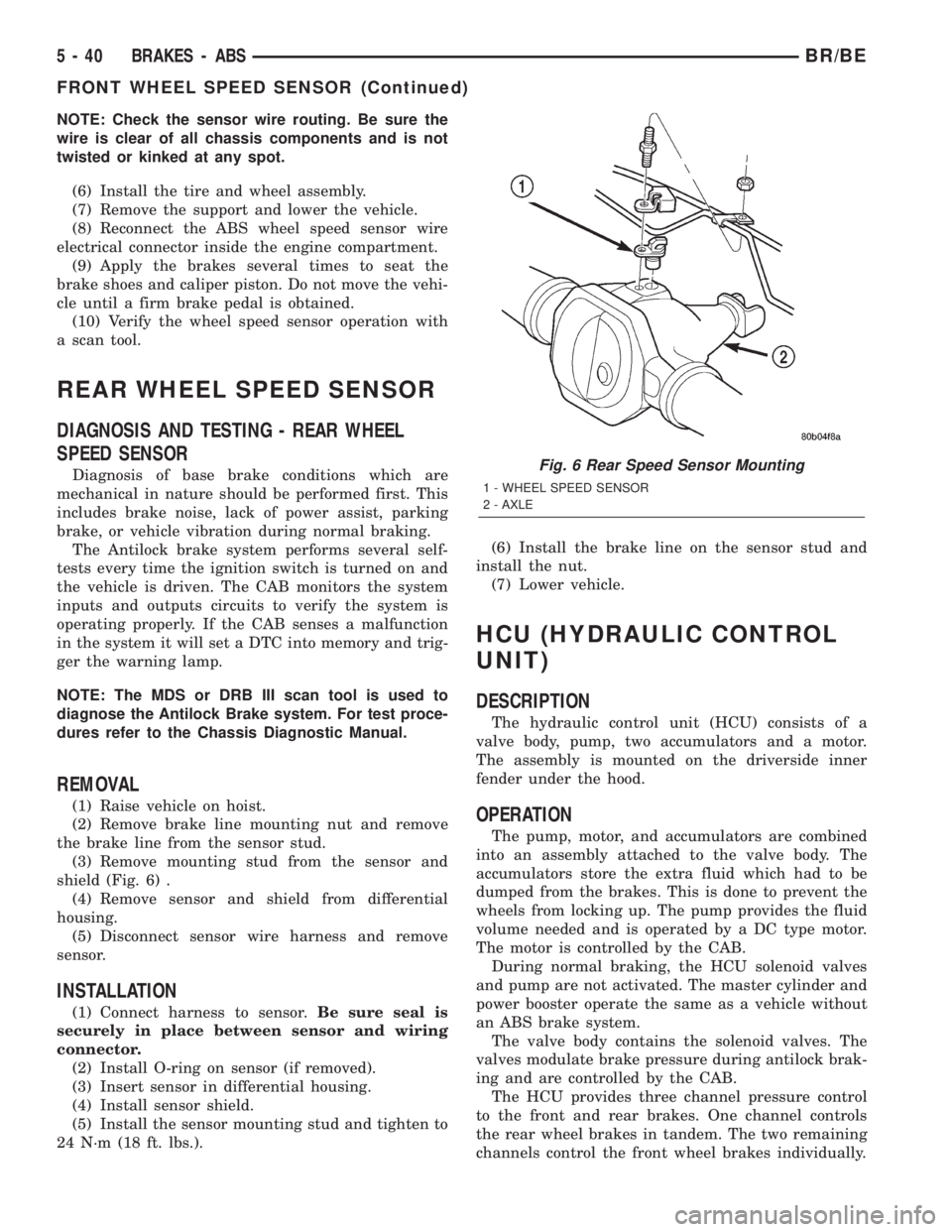
shield (Fig. 6) .
(4) Remove sensor and shield from differential
housing.
(5) Disconnect sensor wire harness and remove
sensor.
INSTALLATION
(1) Connect harness to sensor.Be sure seal is
securely in place between sensor and wiring
connector.
(2) Install O-ring on sensor (if removed).
(3) Insert sensor in differential housing.
(4) Install sensor shield.
(5) Install the sensor mounting stud and tighten to
24 N´m (18 ft. lbs.).(6) Install the brake line on the sensor stud and
install the nut.
(7) Lower vehicle.
HCU (HYDRAULIC CONTROL
UNIT)
DESCRIPTION
The hydraulic control unit (HCU) consists of a
valve body, pump, two accumulators and a motor.
The assembly is mounted on the driverside inner
fender under the hood.
OPERATION
The pump, motor, and accumulators are combined
into an assembly attached to the valve body. The
accumulators store the extra fluid which had to be
dumped from the brakes. This is done to prevent the
wheels from locking up. The pump provides the fluid
volume needed and is operated by a DC type motor.
The motor is controlled by the CAB.
During normal braking, the HCU solenoid valves
and pump are not activated. The master cylinder and
power booster operate the same as a vehicle without
an ABS brake system.
The valve body contains the solenoid valves. The
valves modulate brake pressure during antilock brak-
ing and are controlled by the CAB.
The HCU provides three channel pressure control
to the front and rear brakes. One channel controls
the rear wheel brakes in tandem. The two remaining
channels control the front wheel brakes individually.
Fig. 6 Rear Speed Sensor Mounting
1 - WHEEL SPEED SENSOR
2 - AXLE
5 - 40 BRAKES - ABSBR/BE
FRONT WHEEL SPEED SENSOR (Continued)
Page 230 of 2255
During antilock braking, the solenoid valves are
opened and closed as needed. The valves are not
static. They are cycled rapidly and continuously to
modulate pressure and control wheel slip and decel-
eration.
During antilock braking, solenoid valve pressure
modulation occurs in three stages, pressure decrease,
pressure hold, and pressure increase. The valves are
all contained in the valve body portion of the HCU.
PRESSURE DECREASE
The inlet valve is closed and the outlet valve is
opened during the pressure decrease cycle.
A pressure decrease cycle is initiated when speed
sensor signals indicate high wheel slip at one or
more wheels. At this point, the CAB closes the inlet
to prevent the driver from further increasing the
brake pressure and locking the brakes. The CAB
then opens the outlet valve, which also opens the
return circuit to the accumulators. Fluid pressure is
allowed to bleed off (decrease) as needed to prevent
wheel lock.
Once the period of high wheel slip has ended, the
CAB closes the outlet valve and begins a pressure
increase or hold cycle as needed.
PRESSURE HOLD
Both solenoid valves are closed in the pressure
hold cycle. Fluid apply pressure in the control chan-
nel is maintained at a constant rate. The CAB main-
tains the hold cycle until sensor inputs indicate a
pressure change is necessary.
PRESSURE INCREASE
The inlet valve is open and the outlet valve is
closed during the pressure increase cycle. The pres-
sure increase cycle is used to counteract unequal
wheel speeds. This cycle controls re-application of
fluid apply pressure due to changing road surfaces or
wheel speed.
REMOVAL
(1) Disconnect battery negative cable.
(2) Push the harness connector locks to release the
locks, then remove the connectors from the CAB.
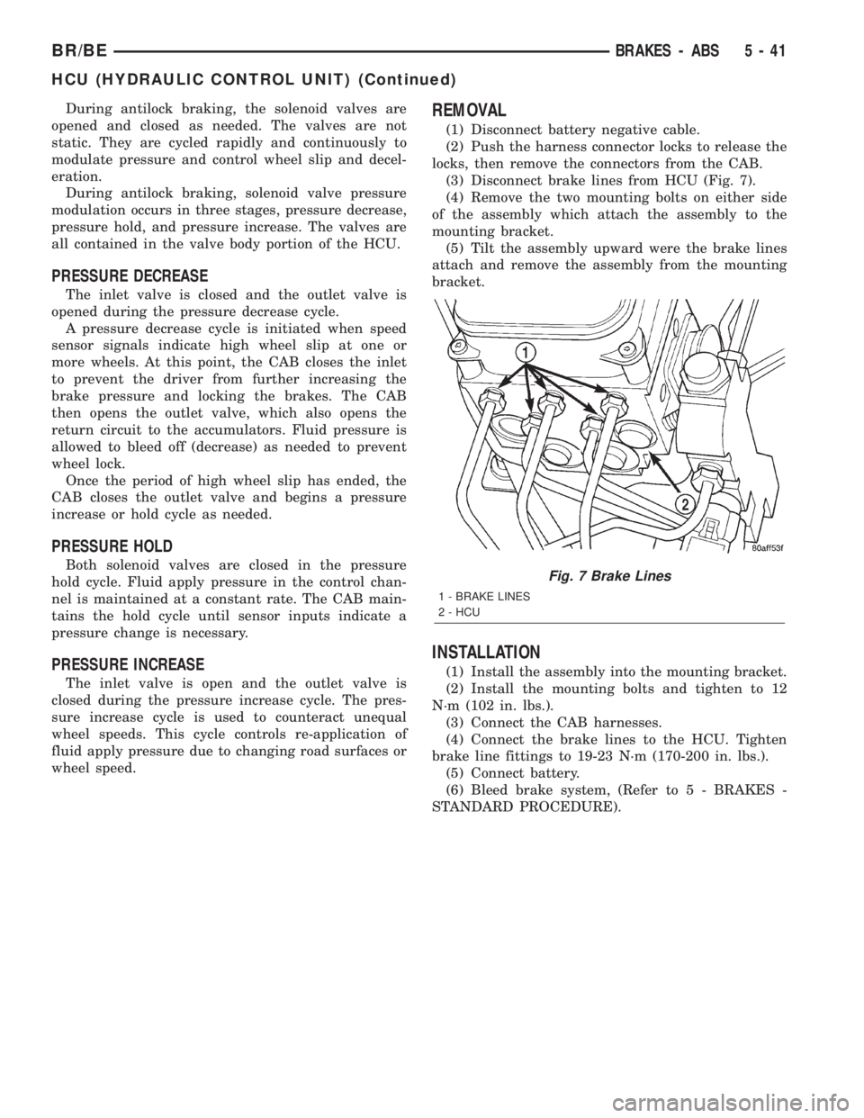
(3) Disconnect brake lines from HCU (Fig. 7).
(4) Remove the two mounting bolts on either side
of the assembly which attach the assembly to the
mounting bracket.
(5) Tilt the assembly upward were the brake lines
attach and remove the assembly from the mounting
bracket.
INSTALLATION
(1) Install the assembly into the mounting bracket.
(2) Install the mounting bolts and tighten to 12
N´m (102 in. lbs.).
(3) Connect the CAB harnesses.
(4) Connect the brake lines to the HCU. Tighten
brake line fittings to 19-23 N´m (170-200 in. lbs.).
(5) Connect battery.
(6) Bleed brake system, (Refer to 5 - BRAKES -
STANDARD PROCEDURE).
Fig. 7 Brake Lines
1 - BRAKE LINES
2 - HCU
BR/BEBRAKES - ABS 5 - 41
HCU (HYDRAULIC CONTROL UNIT) (Continued)
Page 232 of 2255
CLUTCH
TABLE OF CONTENTS
page page
CLUTCH
DESCRIPTION..........................1
OPERATION............................2
WARNING.............................2
DIAGNOSIS AND TESTING - CLUTCH........2
SPECIFICATIONS - CLUTCH...............7
CLUTCH DISC
REMOVAL.............................7
INSTALLATION..........................8
CLUTCH HOUSING
DIAGNOSIS AND TESTING - CLUTCH
HOUSING............................9
REMOVAL.............................11
INSTALLATION.........................11
CLUTCH RELEASE BEARING
REMOVAL.............................12
INSTALLATION.........................12FLYWHEEL
DIAGNOSIS AND TESTING - FLYWHEEL.....13
DISASSEMBLY.........................13
ASSEMBLY............................14
PILOT BEARING
REMOVAL.............................14
INSTALLATION.........................14
CLUTCH PEDAL
REMOVAL.............................15
INSTALLATION.........................15
LINKAGE
REMOVAL.............................15
INSTALLATION.........................16
CLUTCH PEDAL POSITION SWITCH
DESCRIPTION.........................17
OPERATION...........................17
CLUTCH
DESCRIPTION
The clutch mechanism consists of a flywheel, dry-
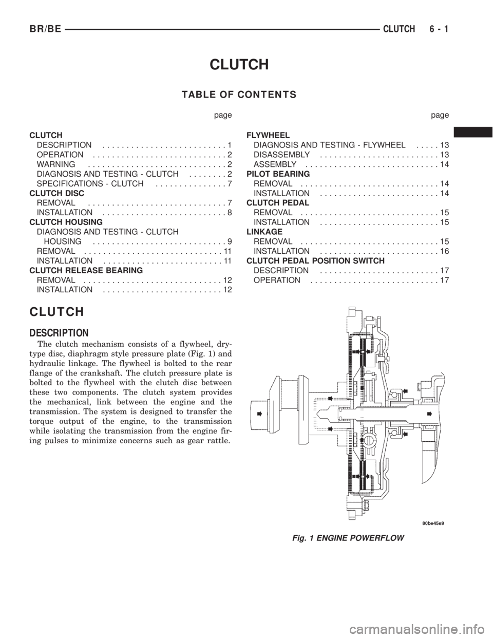
type disc, diaphragm style pressure plate (Fig. 1) and
hydraulic linkage. The flywheel is bolted to the rear
flange of the crankshaft. The clutch pressure plate is
bolted to the flywheel with the clutch disc between
these two components. The clutch system provides
the mechanical, link between the engine and the
transmission. The system is designed to transfer the
torque output of the engine, to the transmission
while isolating the transmission from the engine fir-
ing pulses to minimize concerns such as gear rattle.
Fig. 1 ENGINE POWERFLOW
BR/BECLUTCH 6 - 1
Page 233 of 2255

OPERATION
When the clutch pedal is depressed, it actuates the
clutch master cylinder. This sends hydraulic pressure
to the clutch slave cylinder. The release fork is then
actuated by the slave cylinder mounted on the trans-
mission housing. The release fork pivots on a ball
stud mounted in the transmission housing and
pushes the release bearing. The release bearing then
depresses the pressure plate spring fingers, thereby
releasing pressure on the clutch disc and allowing
the engine crankshaft to spin independently of the
transmission input shaft (Fig. 2).
WARNING
WARNING: EXERCISE CARE WHEN SERVICING
CLUTCH COMPONENTS. FACTORY INSTALLED
CLUTCH DISCS DO NOT CONTAIN ASBESTOS
FIBERS. DUST AND DIRT ON CLUTCH PARTS MAY
CONTAIN ASBESTOS FIBERS FROM AFTERMAR-
KET COMPONENTS. BREATHING EXCESSIVE CON-
CENTRATIONS OF THESE FIBERS CAN CAUSE
SERIOUS BODILY HARM. WEAR A RESPIRATOR
DURING SERVICE AND NEVER CLEAN CLUTCH
COMPONENTS WITH COMPRESSED AIR OR WITH
A DRY BRUSH. EITHER CLEAN THE COMPONENTSWITH A WATER DAMPENED RAGS OR USE A VAC-
UUM CLEANER SPECIFICALLY DESIGNED FOR
REMOVING ASBESTOS FIBERS AND DUST. DO NOT
CREATE DUST BY SANDING A CLUTCH DISC.
REPLACE THE DISC IF THE FRICTION MATERIAL IS
DAMAGED OR CONTAMINATED. DISPOSE OF ALL
DUST AND DIRT CONTAINING ASBESTOS FIBERS
IN SEALED BAGS OR CONTAINERS. THIS WILL
HELP MINIMIZE EXPOSURE TO YOURSELF AND TO
OTHERS. FOLLOW ALL RECOMMENDED SAFETY
PRACTICES PRESCRIBED BY THE OCCUPATIONAL
SAFETY AND HEALTH ADMINISTRATION (OSHA)
AND THE ENVIRONMENTAL SAFETY AGENCY
(EPA), FOR THE HANDLING AND DISPOSAL OF
PRODUCTS CONTAINING ASBESTOS.
DIAGNOSIS AND TESTING - CLUTCH
A road test and component inspection (Fig. 3) is
recommended to determine a clutch problem.
During a road test, drive the vehicle at normal
speeds. Shift the transmission through all gear
ranges and observe clutch action. If the clutch chat-
ters, grabs, slips or does not release properly, remove
and inspect the clutch components. If the problem is
noise or hard shifting, further diagnosis may be
needed as the transmission or another driveline com-
ponent may be at fault.
CLUTCH CONTAMINATION
Fluid contamination is a frequent cause of clutch
malfunctions. Oil, water or clutch fluid on the clutch
disc and pressure plate surfaces will cause chatter,
slip and grab.
During inspection, note if any components are con-
taminated with oil, hydraulic fluid or water/road
splash.
Oil contamination indicates a leak at either the
rear main seal or transmission input shaft. Oil leak-
age produces a residue of oil on the housing interior
and on the clutch cover and flywheel. Heat buildup
caused by slippage between the cover, disc and fly-
wheel, can sometimes bake the oil residue onto the
components. The glaze-like residue ranges in color
from amber to black.
Road splash contamination means dirt/water is
entering the clutch housing due to loose bolts, hous-
ing cracks or through hydraulic line openings. Driv-
ing through deep water puddles can force water/road
splash into the housing through such openings.
Clutch fluid leaks are usually from damaged slave
cylinder push rod seals.
Fig. 2 CLUTCH OPERATION
1 - FLYWHEEL
2 - PRESSURE PLATE FINGERS
3 - PIVOT POINT
4 - RELEASE BEARING PUSHED IN
5 - CLUTCH DISC ENGAGED
6 - CLUTCH DISC ENGAGED
7 - RELEASE BEARING
6 - 2 CLUTCHBR/BE
CLUTCH (Continued)
Page 235 of 2255

IMPROPER RELEASE OR CLUTCH ENGAGEMENT
Clutch release or engagement problems are caused
by wear or damage to one or more clutch compo-
nents. A visual inspection of the release components
will usually reveal the problem part.
Release problems can result in hard shifting and
noise. Items to look for are: leaks at the clutch cylin-
ders and interconnecting line; loose slave cylinder
bolts; worn/loose release fork and pivot stud; dam-
aged release bearing; and a worn clutch disc, or pres-
sure plate.
Normal condensation in vehicles that are stored or
out of service for long periods of time can generate
enough corrosion to make the disc stick to the fly-
wheel, or pressure plate. If this condition is experi-
enced, correction only requires that the disc be
loosened manually through the inspection plate open-
ing.
Engagement problems usually result in slip, chat-
ter/shudder, and noisy operation. The primary causes
are clutch disc contamination; clutch disc wear; mis-
alignment, or distortion; flywheel damage; or a com-
bination of the foregoing. A visual inspection is
required to determine the part actually causing the
problem.
CLUTCH MISALIGNMENT
Clutch components must be in proper alignment
with the crankshaft and transmission input shaft.
Misalignment caused by excessive runout or warpage
of any clutch component will cause grab, chatter and
improper clutch release.
CLUTCH COVER AND DISC RUNOUT
Check the clutch disc before installation. Axial
(face) runout of anewdisc should not exceed 0.50
mm (0.020 in.). Measure runout about 6 mm (1/4 in.)
from the outer edge of the disc facing. Obtain
another disc if runout is excessive.
Check condition of the clutch before installation. A
warped cover or diaphragm spring will cause grab
and incomplete release or engagement. Be careful
when handling the cover and disc. Impact can distort
the cover, diaphragm spring, release fingers and the
hub of the clutch disc.
Use an alignment tool when positioning the disc on
the flywheel. The tool prevents accidental misalign-
ment which could result in cover distortion and disc
damage.
A frequent cause of clutch cover distortion (and
consequent misalignment) is improper bolt tighten-
ing.
DIAGNOSIS CHART
The clutch inspection chart (Fig. 3) outlines items
to be checked before and during clutch installation.
Use the chart as a check list to help avoid overlook-
ing potential problem sources during service opera-
tions.
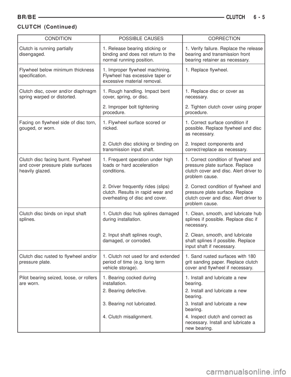
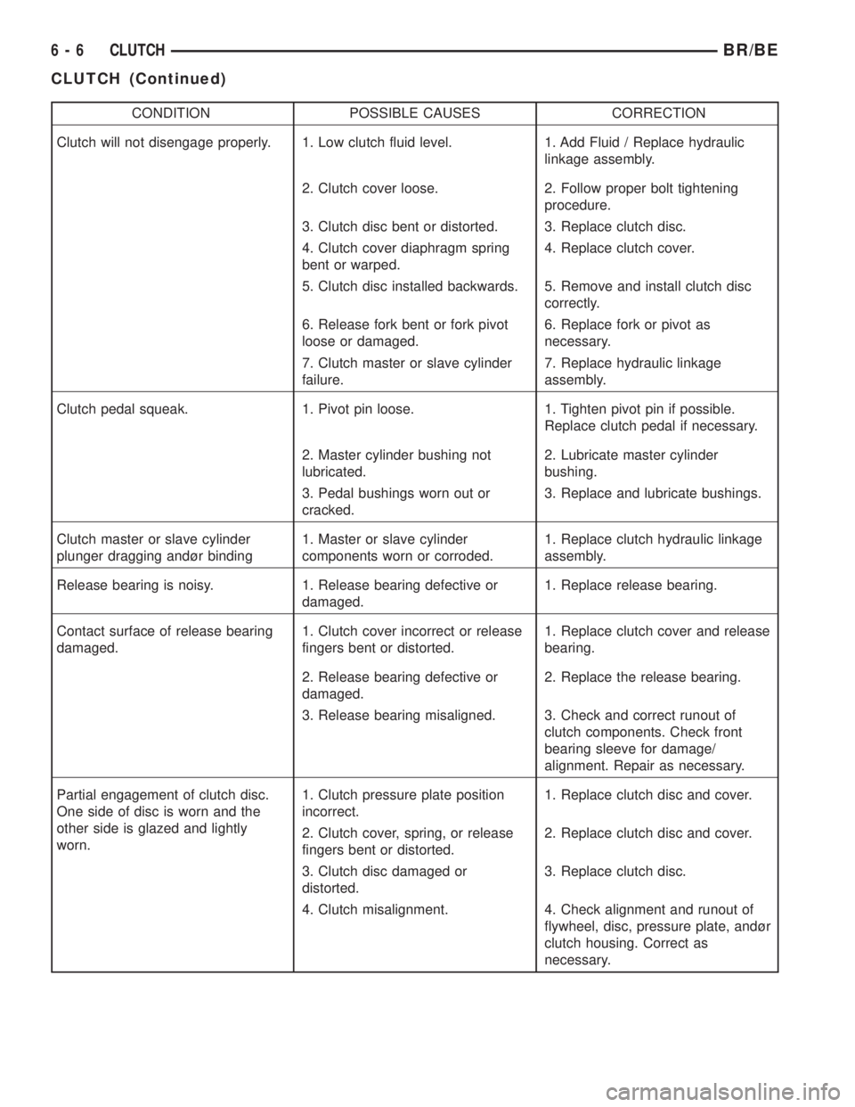
The diagnosis charts Diagnosis Chart describe
common clutch problems, causes and correction.
Fault conditions are listed at the top of each chart.
Conditions, causes and corrective action are outlined
in the indicated columns.
The charts are provided as a convenient reference
when diagnosing faulty clutch operation.
DIAGNOSIS CHART
CONDITION POSSIBLE CAUSES CORRECTION
Disc facing worn out 1. Normal wear. 1. Replace cover and disc.
2. Driver frequently rides (slips) the
clutch. Results in rapid overheating
and wear.2. Replace cover and disc.
3. Insufficient clutch cover
diaphragm spring tension.3. Replace cover and disc.
Clutch disc facing contaminated with
oil, grease, or clutch fluid.1. Leak at rear main engine seal or
transmission input shaft seal.1. Replace appropriate seal.
2. Excessive amount of grease
applied to the input shaft splines.2. Remove grease and apply the
correct amount of grease.
3. Road splash, water entering
housing.3. Replace clutch disc. Clean clutch
cover and reuse if in good condition.
4. Slave cylinder leaking. 4. Replace hydraulic clutch linkage.
6 - 4 CLUTCHBR/BE
CLUTCH (Continued)
Page 236 of 2255
CONDITION POSSIBLE CAUSES CORRECTION
Clutch is running partially
disengaged.1. Release bearing sticking or
binding and does not return to the
normal running position.1. Verify failure. Replace the release
bearing and transmission front
bearing retainer as necessary.
Flywheel below minimum thickness
specification.1. Improper flywheel machining.
Flywheel has excessive taper or
excessive material removal.1. Replace flywheel.
Clutch disc, cover and/or diaphragm
spring warped or distorted.1. Rough handling. Impact bent
cover, spring, or disc.1. Replace disc or cover as
necessary.
2. Improper bolt tightening
procedure.2. Tighten clutch cover using proper
procedure.
Facing on flywheel side of disc torn,
gouged, or worn.1. Flywheel surface scored or
nicked.1. Correct surface condition if
possible. Replace flywheel and disc
as necessary.
2. Clutch disc sticking or binding on
transmission input shaft.2. Inspect components and
correct/replace as necessary.
Clutch disc facing burnt. Flywheel
and cover pressure plate surfaces
heavily glazed.1. Frequent operation under high
loads or hard acceleration
conditions.1. Correct condition of flywheel and
pressure plate surface. Replace
clutch cover and disc. Alert driver to
problem cause.
2. Driver frequently rides (slips)
clutch. Results in rapid wear and
overheating of disc and cover.2. Correct condition of flywheel and
pressure plate surface. Replace
clutch cover and disc. Alert driver to
problem cause.
Clutch disc binds on input shaft
splines.1. Clutch disc hub splines damaged
during installation.1. Clean, smooth, and lubricate hub
splines if possible. Replace disc if
necessary.
2. Input shaft splines rough,
damaged, or corroded.2. Clean, smooth, and lubricate
shaft splines if possible. Replace
input shaft if necessary.
Clutch disc rusted to flywheel and/or
pressure plate.1. Clutch not used for and extended
period of time (e.g. long term
vehicle storage).1. Sand rusted surfaces with 180
grit sanding paper. Replace clutch
cover and flywheel if necessary.
Pilot bearing seized, loose, or rollers
are worn.1. Bearing cocked during
installation.1. Install and lubricate a new
bearing.
2. Bearing defective. 2. Install and lubricate a new
bearing.
3. Bearing not lubricated. 3. Install and lubricate a new
bearing.
4. Clutch misalignment. 4. Inspect clutch and correct as
necessary. Install and lubricate a
new bearing.
BR/BECLUTCH 6 - 5
CLUTCH (Continued)
Page 237 of 2255
CONDITION POSSIBLE CAUSES CORRECTION
Clutch will not disengage properly. 1. Low clutch fluid level. 1. Add Fluid / Replace hydraulic
linkage assembly.
2. Clutch cover loose. 2. Follow proper bolt tightening
procedure.
3. Clutch disc bent or distorted. 3. Replace clutch disc.
4. Clutch cover diaphragm spring
bent or warped.4. Replace clutch cover.
5. Clutch disc installed backwards. 5. Remove and install clutch disc
correctly.
6. Release fork bent or fork pivot
loose or damaged.6. Replace fork or pivot as
necessary.
7. Clutch master or slave cylinder
failure.7. Replace hydraulic linkage
assembly.
Clutch pedal squeak. 1. Pivot pin loose. 1. Tighten pivot pin if possible.
Replace clutch pedal if necessary.
2. Master cylinder bushing not
lubricated.2. Lubricate master cylinder
bushing.
3. Pedal bushings worn out or
cracked.3. Replace and lubricate bushings.
Clutch master or slave cylinder
plunger dragging andùr binding1. Master or slave cylinder
components worn or corroded.1. Replace clutch hydraulic linkage
assembly.
Release bearing is noisy. 1. Release bearing defective or
damaged.1. Replace release bearing.
Contact surface of release bearing
damaged.1. Clutch cover incorrect or release
fingers bent or distorted.1. Replace clutch cover and release
bearing.
2. Release bearing defective or
damaged.2. Replace the release bearing.
3. Release bearing misaligned. 3. Check and correct runout of
clutch components. Check front
bearing sleeve for damage/
alignment. Repair as necessary.
Partial engagement of clutch disc.
One side of disc is worn and the
other side is glazed and lightly
worn.1. Clutch pressure plate position
incorrect.1. Replace clutch disc and cover.
2. Clutch cover, spring, or release
fingers bent or distorted.2. Replace clutch disc and cover.
3. Clutch disc damaged or
distorted.3. Replace clutch disc.
4. Clutch misalignment. 4. Check alignment and runout of
flywheel, disc, pressure plate, andùr
clutch housing. Correct as
necessary.
6 - 6 CLUTCHBR/BE
CLUTCH (Continued)