2002 DODGE RAM wheel
[x] Cancel search: wheelPage 84 of 2255

AXLE SHAFTS
REMOVAL
(1) Raise and support the vehicle.
(2) Remove wheel and tire assembly.
(3) Remove brake caliper, rotor and ABS wheel
speed sensor if equipped. Refer to 5 Brakes for pro-
cedures.
(4) Remove the cotter pin and axle hub nut.
(5) Remove hub bearing bolts (Fig. 21) and remove
hub bearing from the steering knuckle.
(6) Remove brake dust shield from knuckle.
(7) Remove axle shaft from the housing. Avoid
damaging the axle shaft oil seal.
INSTALLATION
(1) Clean axle shaft and apply a thin film of
Mopar Wheel Bearing Grease to the shaft splines,
seal contact surface, hub bore.
(2) Install axle shaft into the housing and differen-
tial side gears. Avoid damaging axle shaft oil seals in
the differential.
(3) Install dust shield and hub bearing on knuckle.
(4) Install hub bearing bolts and tighten to 170
N´m (125 ft. lbs.).
(5) Install axle washer and nut, tighten nut to 237
N´m (175 ft. lbs.). Align nut to next cotter pin hole
and install new cotter pin.
(6) Install ABS wheel speed sensor, brake rotor
and caliper. Refer to Brakes for proper procedures.
(7) Install wheel and tire assembly.
(8) Remove support and lower the vehicle.
BLOCK, ADAPTER ± C-239-37
BLOCK, ADAPTER ± C-239-62
HOLDER, YOKE - 6719A
PINION DEPTH, SET ± 6730
Fig. 21 HUB AND KNUCKLE
1 - KNUCKLE
2 - HUB BEARING
BR/BEFRONT AXLE - 248FBI 3 - 29
FRONT AXLE - 248FBI (Continued)
Page 86 of 2255
AXLE SHAFT SEALS
REMOVAL
(1) Remove hub bearings and axle shafts.
(2) Remove axle shaft seal from the differential
housing with a long drift or punch.Be careful not
to damage housing.
(3) Clean the inside perimeter of the differential
housing with fine crocus cloth.
INSTALLATION
(1) Apply a light film of oil to the inside lip of the
new axle shaft seal.
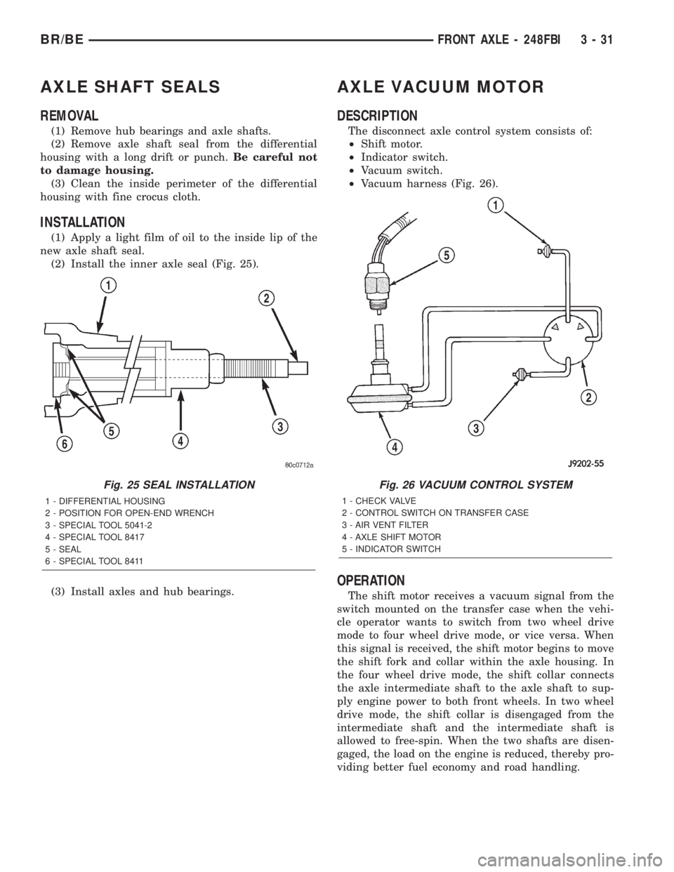
(2) Install the inner axle seal (Fig. 25).
(3) Install axles and hub bearings.
AXLE VACUUM MOTOR
DESCRIPTION
The disconnect axle control system consists of:
²Shift motor.
²Indicator switch.
²Vacuum switch.
²Vacuum harness (Fig. 26).
OPERATION
The shift motor receives a vacuum signal from the
switch mounted on the transfer case when the vehi-
cle operator wants to switch from two wheel drive
mode to four wheel drive mode, or vice versa. When
this signal is received, the shift motor begins to move
the shift fork and collar within the axle housing. In
the four wheel drive mode, the shift collar connects
the axle intermediate shaft to the axle shaft to sup-
ply engine power to both front wheels. In two wheel
drive mode, the shift collar is disengaged from the
intermediate shaft and the intermediate shaft is
allowed to free-spin. When the two shafts are disen-
gaged, the load on the engine is reduced, thereby pro-
viding better fuel economy and road handling.
Fig. 25 SEAL INSTALLATION
1 - DIFFERENTIAL HOUSING
2 - POSITION FOR OPEN-END WRENCH
3 - SPECIAL TOOL 5041-2
4 - SPECIAL TOOL 8417
5 - SEAL
6 - SPECIAL TOOL 8411
Fig. 26 VACUUM CONTROL SYSTEM
1 - CHECK VALVE
2 - CONTROL SWITCH ON TRANSFER CASE
3 - AIR VENT FILTER
4 - AXLE SHIFT MOTOR
5 - INDICATOR SWITCH
BR/BEFRONT AXLE - 248FBI 3 - 31
Page 90 of 2255
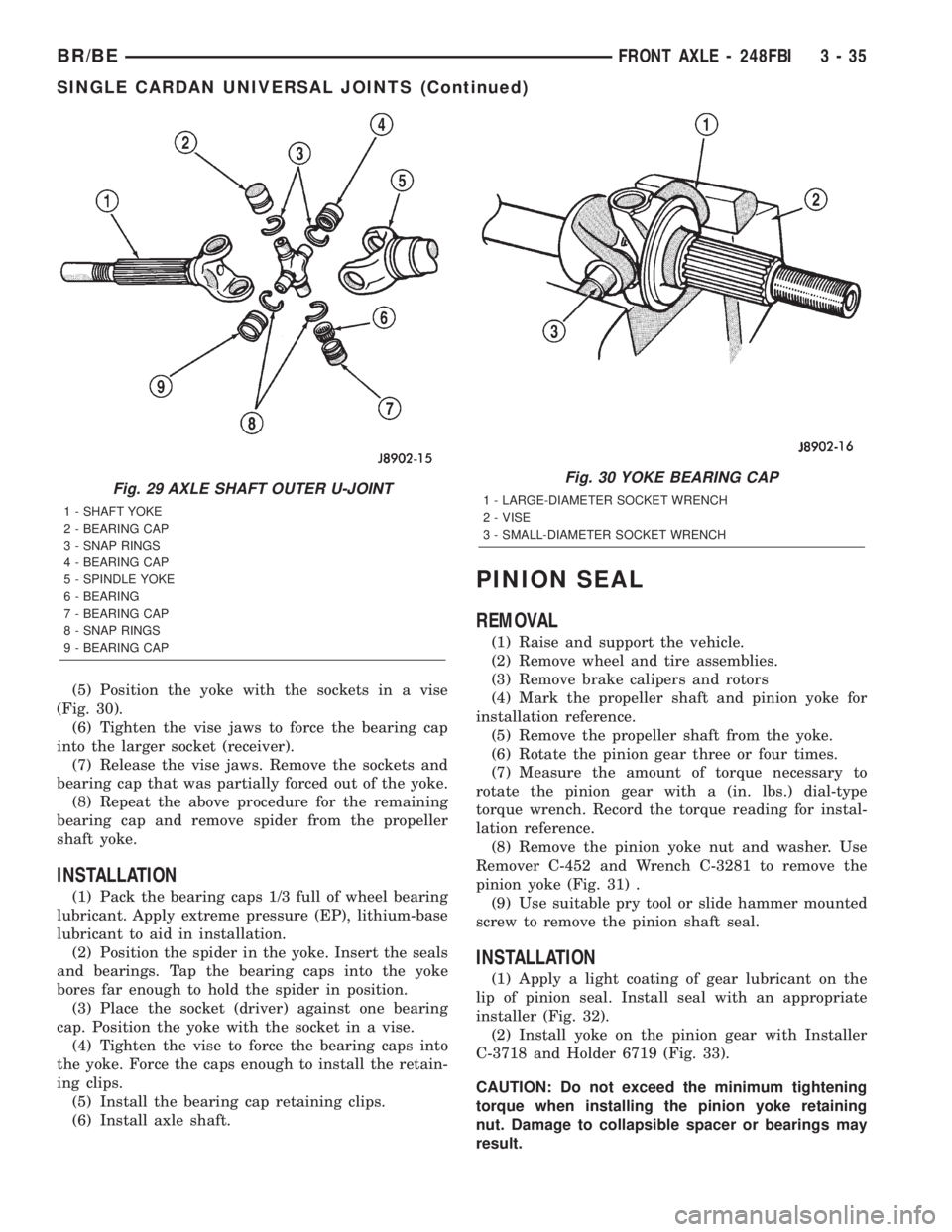
(5) Position the yoke with the sockets in a vise
(Fig. 30).
(6) Tighten the vise jaws to force the bearing cap
into the larger socket (receiver).
(7) Release the vise jaws. Remove the sockets and
bearing cap that was partially forced out of the yoke.
(8) Repeat the above procedure for the remaining
bearing cap and remove spider from the propeller
shaft yoke.
INSTALLATION
(1) Pack the bearing caps 1/3 full of wheel bearing
lubricant. Apply extreme pressure (EP), lithium-base
lubricant to aid in installation.
(2) Position the spider in the yoke. Insert the seals
and bearings. Tap the bearing caps into the yoke
bores far enough to hold the spider in position.
(3) Place the socket (driver) against one bearing
cap. Position the yoke with the socket in a vise.
(4) Tighten the vise to force the bearing caps into
the yoke. Force the caps enough to install the retain-
ing clips.
(5) Install the bearing cap retaining clips.
(6) Install axle shaft.
PINION SEAL
REMOVAL
(1) Raise and support the vehicle.
(2) Remove wheel and tire assemblies.
(3) Remove brake calipers and rotors
(4) Mark the propeller shaft and pinion yoke for
installation reference.
(5) Remove the propeller shaft from the yoke.
(6) Rotate the pinion gear three or four times.
(7) Measure the amount of torque necessary to
rotate the pinion gear with a (in. lbs.) dial-type
torque wrench. Record the torque reading for instal-
lation reference.
(8) Remove the pinion yoke nut and washer. Use
Remover C-452 and Wrench C-3281 to remove the
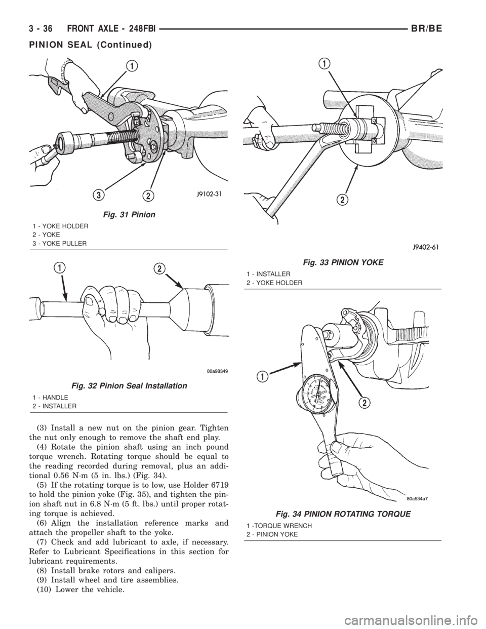
pinion yoke (Fig. 31) .
(9) Use suitable pry tool or slide hammer mounted
screw to remove the pinion shaft seal.
INSTALLATION
(1) Apply a light coating of gear lubricant on the
lip of pinion seal. Install seal with an appropriate
installer (Fig. 32).
(2) Install yoke on the pinion gear with Installer
C-3718 and Holder 6719 (Fig. 33).
CAUTION: Do not exceed the minimum tightening
torque when installing the pinion yoke retaining
nut. Damage to collapsible spacer or bearings may
result.
Fig. 29 AXLE SHAFT OUTER U-JOINT
1 - SHAFT YOKE
2 - BEARING CAP
3 - SNAP RINGS
4 - BEARING CAP
5 - SPINDLE YOKE
6 - BEARING
7 - BEARING CAP
8 - SNAP RINGS
9 - BEARING CAP
Fig. 30 YOKE BEARING CAP
1 - LARGE-DIAMETER SOCKET WRENCH
2 - VISE
3 - SMALL-DIAMETER SOCKET WRENCH
BR/BEFRONT AXLE - 248FBI 3 - 35
SINGLE CARDAN UNIVERSAL JOINTS (Continued)
Page 91 of 2255
(3) Install a new nut on the pinion gear. Tighten
the nut only enough to remove the shaft end play.
(4) Rotate the pinion shaft using an inch pound
torque wrench. Rotating torque should be equal to
the reading recorded during removal, plus an addi-
tional 0.56 N´m (5 in. lbs.) (Fig. 34).
(5) If the rotating torque is to low, use Holder 6719
to hold the pinion yoke (Fig. 35), and tighten the pin-
ion shaft nut in 6.8 N´m (5 ft. lbs.) until proper rotat-
ing torque is achieved.
(6) Align the installation reference marks and
attach the propeller shaft to the yoke.
(7) Check and add lubricant to axle, if necessary.
Refer to Lubricant Specifications in this section for
lubricant requirements.
(8) Install brake rotors and calipers.
(9) Install wheel and tire assemblies.
(10) Lower the vehicle.
Fig. 31 Pinion
1 - YOKE HOLDER
2 - YOKE
3 - YOKE PULLER
Fig. 32 Pinion Seal Installation
1 - HANDLE
2 - INSTALLER
Fig. 33 PINION YOKE
1 - INSTALLER
2 - YOKE HOLDER
Fig. 34 PINION ROTATING TORQUE
1 -TORQUE WRENCH
2 - PINION YOKE
3 - 36 FRONT AXLE - 248FBIBR/BE
PINION SEAL (Continued)
Page 101 of 2255
REAR AXLE - 248RBI
TABLE OF CONTENTS
page page
REAR AXLE - 248RBI
DESCRIPTION.........................46
OPERATION...........................46
DIAGNOSIS AND TESTING - AXLE..........47
REMOVAL.............................51
INSTALLATION.........................51
ADJUSTMENTS........................51
SPECIFICATIONS
REAR AXLE - 248RBI..................59
SPECIAL TOOLS
REAR AXLE - 248RBI..................59
AXLE SHAFTS
REMOVAL.............................62
INSTALLATION.........................62
AXLE BEARINGS
REMOVAL.............................62
INSTALLATION.........................62
PINION SEAL
REMOVAL.............................63INSTALLATION.........................63
DIFFERENTIAL
REMOVAL.............................64
DISASSEMBLY.........................65
ASSEMBLY............................66
INSTALLATION.........................66
DIFFERENTIAL - TRAC-LOK
DIAGNOSIS AND TESTING - TRAC-LOKT.....67
DISASSEMBLY.........................68
ASSEMBLY............................70
DIFFERENTIAL CASE BEARINGS
REMOVAL.............................72
INSTALLATION.........................72
PINION GEAR/RING GEAR/TONE RING
REMOVAL.............................73
INSTALLATION.........................75
REAR AXLE - 248RBI
DESCRIPTION
The Rear Beam-design Iron (RBI) axle housings consist
of an iron center casting (differential housing) with axle
shaft tubes extending from either side. The tubes are
pressed into the differential housing and welded. The
axles are equipped with full-floating axle shafts, meaning
that loads are supported by the axle housing tubes.
The differential case for the standard differentials
and the Trac-loktdifferential are a one-piece design.
Differential bearing preload and ring gear backlash
are adjusted by the use of shims located between the
differential bearing cones and case. Pinion bearing
preload is set and maintained by the use of a collaps-
ible spacer. The removable, stamped steel cover pro-
vides a means for inspection and service.
OPERATION
STANDARD DIFFERENTIAL
The axle receives power from the transmission/
transfer case through the rear propeller shaft. The
rear propeller shaft is connected to the pinion gear
which rotates the differential through the gear mesh
with the ring gear bolted to the differential case. The
engine power is transmitted to the axle shaftsthrough the pinion mate and side gears. The side
gears are splined to the axle shafts.
During straight-ahead driving, the differential pin-
ion gears do not rotate on the pinion mate shaft. This
occurs because input torque applied to the gears is
divided and distributed equally between the two side
gears. As a result, the pinion gears revolve with the
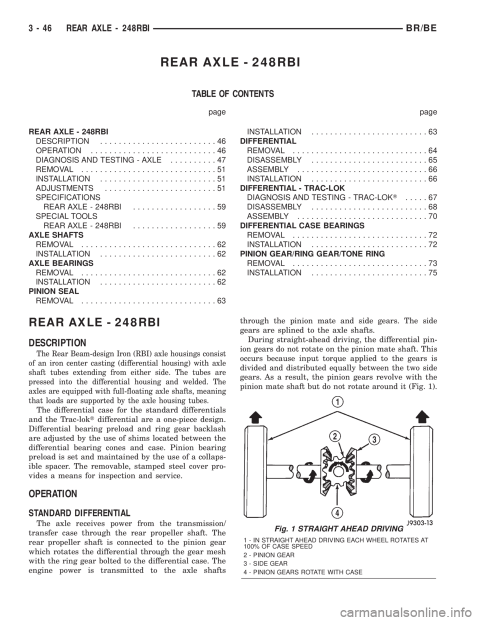
pinion mate shaft but do not rotate around it (Fig. 1).Fig. 1 STRAIGHT AHEAD DRIVING
1 - IN STRAIGHT AHEAD DRIVING EACH WHEEL ROTATES AT
100% OF CASE SPEED
2 - PINION GEAR
3 - SIDE GEAR
4 - PINION GEARS ROTATE WITH CASE
3 - 46 REAR AXLE - 248RBIBR/BE
Page 102 of 2255

When turning corners, the outside wheel must
travel a greater distance than the inside wheel to
complete a turn. The difference must be compensated
for to prevent the tires from scuffing and skidding
through turns. To accomplish this, the differential
allows the axle shafts to turn at unequal speeds (Fig.
2). In this instance, the input torque applied to the
pinion gears is not divided equally. The pinion gears
now rotate around the pinion mate shaft in opposite
directions. This allows the side gear and axle shaft
attached to the outside wheel to rotate at a faster
speed.
TRAC-LOKTDIFFERENTIAL
The differential clutches are engaged by two con-
current forces. The first being the preload force
exerted through Belleville spring washers within the
clutch packs. The second is the separating forces gen-
erated by the side gears as torque is applied through
the ring gear (Fig. 3).
This design provides the differential action needed
for turning corners and for driving straight ahead
during periods of unequal traction. When one wheel
looses traction, the clutch packs transfer additional
torque to the wheel having the most traction. The
differential resist wheel spin on bumpy roads and
provide more pulling power when one wheel looses
traction. Pulling power is provided continuously until
both wheels loose traction. If both wheels slip due to
unequal traction, Trac-loktoperation is normal. In
extreme cases of differences of traction, the wheel
with the least traction may spin.
DIAGNOSIS AND TESTING - AXLE
GEAR NOISE
Axle gear noise can be caused by insufficient lubri-
cant, incorrect backlash, incorrect pinion depth, toothcontact, worn/damaged gears, or the carrier housing
not having the proper offset and squareness.
Gear noise usually happens at a specific speed
range. The noise can also occur during a specific type
of driving condition. These conditions are accelera-
tion, deceleration, coast, or constant load.
When road testing, first warm-up the axle fluid by
driving the vehicle at least 5 miles and then acceler-
ate the vehicle to the speed range where the noise is
the greatest. Shift out-of-gear and coast through the
peak-noise range. If the noise stops or changes
greatly:
²Check for insufficient lubricant.
²Incorrect ring gear backlash.
²Gear damage.
Differential side gears and pinions can be checked
by turning the vehicle. They usually do not cause
noise during straight-ahead driving when the gears
are unloaded. The side gears are loaded during vehi-
Fig. 2 DIFFERENTIAL ON TURNS
1 - PINION GEARS ROTATE ON PINION SHAFTFig. 3 TRAC-LOK LIMITED SLIP DIFFERENTIAL
1 - CASE
2 - RING GEAR
3 - DRIVE PINION
4 - PINION GEAR
5 - MATE SHAFT
6 - CLUTCH PACK
7 - SIDE GEAR
8 - CLUTCH PACK
BR/BEREAR AXLE - 248RBI 3 - 47
REAR AXLE - 248RBI (Continued)
Page 103 of 2255
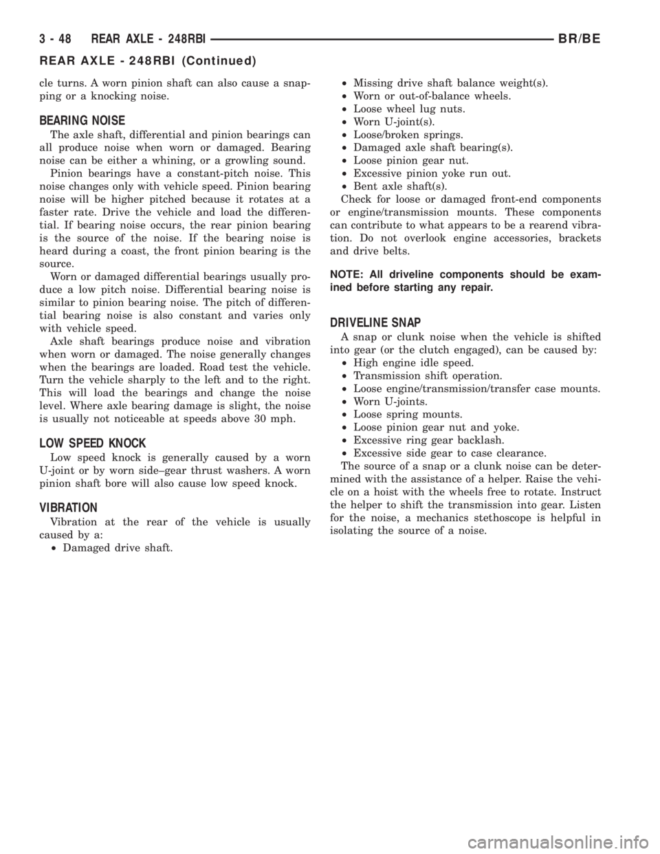
cle turns. A worn pinion shaft can also cause a snap-
ping or a knocking noise.
BEARING NOISE
The axle shaft, differential and pinion bearings can
all produce noise when worn or damaged. Bearing
noise can be either a whining, or a growling sound.
Pinion bearings have a constant-pitch noise. This
noise changes only with vehicle speed. Pinion bearing
noise will be higher pitched because it rotates at a
faster rate. Drive the vehicle and load the differen-
tial. If bearing noise occurs, the rear pinion bearing
is the source of the noise. If the bearing noise is
heard during a coast, the front pinion bearing is the
source.
Worn or damaged differential bearings usually pro-
duce a low pitch noise. Differential bearing noise is
similar to pinion bearing noise. The pitch of differen-
tial bearing noise is also constant and varies only
with vehicle speed.
Axle shaft bearings produce noise and vibration
when worn or damaged. The noise generally changes
when the bearings are loaded. Road test the vehicle.
Turn the vehicle sharply to the left and to the right.
This will load the bearings and change the noise
level. Where axle bearing damage is slight, the noise
is usually not noticeable at speeds above 30 mph.
LOW SPEED KNOCK
Low speed knock is generally caused by a worn
U-joint or by worn side±gear thrust washers. A worn
pinion shaft bore will also cause low speed knock.
VIBRATION
Vibration at the rear of the vehicle is usually
caused by a:
²Damaged drive shaft.²Missing drive shaft balance weight(s).
²Worn or out-of-balance wheels.
²Loose wheel lug nuts.
²Worn U-joint(s).
²Loose/broken springs.
²Damaged axle shaft bearing(s).
²Loose pinion gear nut.
²Excessive pinion yoke run out.
²Bent axle shaft(s).
Check for loose or damaged front-end components
or engine/transmission mounts. These components
can contribute to what appears to be a rearend vibra-
tion. Do not overlook engine accessories, brackets
and drive belts.
NOTE: All driveline components should be exam-
ined before starting any repair.
DRIVELINE SNAP
A snap or clunk noise when the vehicle is shifted
into gear (or the clutch engaged), can be caused by:
²High engine idle speed.
²Transmission shift operation.
²Loose engine/transmission/transfer case mounts.
²Worn U-joints.
²Loose spring mounts.
²Loose pinion gear nut and yoke.
²Excessive ring gear backlash.
²Excessive side gear to case clearance.
The source of a snap or a clunk noise can be deter-
mined with the assistance of a helper. Raise the vehi-
cle on a hoist with the wheels free to rotate. Instruct
the helper to shift the transmission into gear. Listen
for the noise, a mechanics stethoscope is helpful in
isolating the source of a noise.
3 - 48 REAR AXLE - 248RBIBR/BE
REAR AXLE - 248RBI (Continued)
Page 104 of 2255
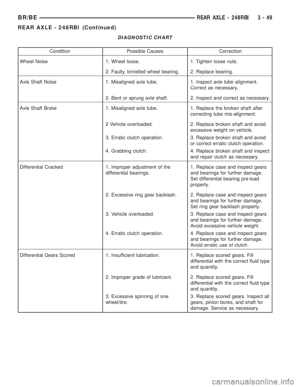
DIAGNOSTIC CHART
Condition Possible Causes Correction
Wheel Noise 1. Wheel loose. 1. Tighten loose nuts.
2. Faulty, brinelled wheel bearing. 2. Replace bearing.
Axle Shaft Noise 1. Misaligned axle tube. 1. Inspect axle tube alignment.
Correct as necessary.
2. Bent or sprung axle shaft. 2. Inspect and correct as necessary.
Axle Shaft Broke 1. Misaligned axle tube. 1. Replace the broken shaft after
correcting tube mis-alignment.
2 Vehicle overloaded. 2. Replace broken shaft and avoid
excessive weight on vehicle.
3. Erratic clutch operation. 3. Replace broken shaft and avoid
or correct erratic clutch operation.
4. Grabbing clutch. 4. Replace broken shaft and inspect
and repair clutch as necessary.
Differential Cracked 1. Improper adjustment of the
differential bearings.1. Replace case and inspect gears
and bearings for further damage.
Set differential bearing pre-load
properly.
2. Excessive ring gear backlash. 2. Replace case and inspect gears
and bearings for further damage.
Set ring gear backlash properly.
3. Vehicle overloaded. 3. Replace case and inspect gears
and bearings for further damage.
Avoid excessive vehicle weight.
4. Erratic clutch operation. 4. Replace case and inspect gears
and bearings for further damage.
Avoid erratic use of clutch.
Differential Gears Scored 1. Insufficient lubrication. 1. Replace scored gears. Fill
differential with the correct fluid type
and quantity.
2. Improper grade of lubricant. 2. Replace scored gears. Fill
differential with the correct fluid type
and quantity.
3. Excessive spinning of one
wheel/tire.3. Replace scored gears. Inspect all
gears, pinion bores, and shaft for
damage. Service as necessary.
BR/BEREAR AXLE - 248RBI 3 - 49
REAR AXLE - 248RBI (Continued)