2002 DODGE RAM automatic transmission
[x] Cancel search: automatic transmissionPage 680 of 2255
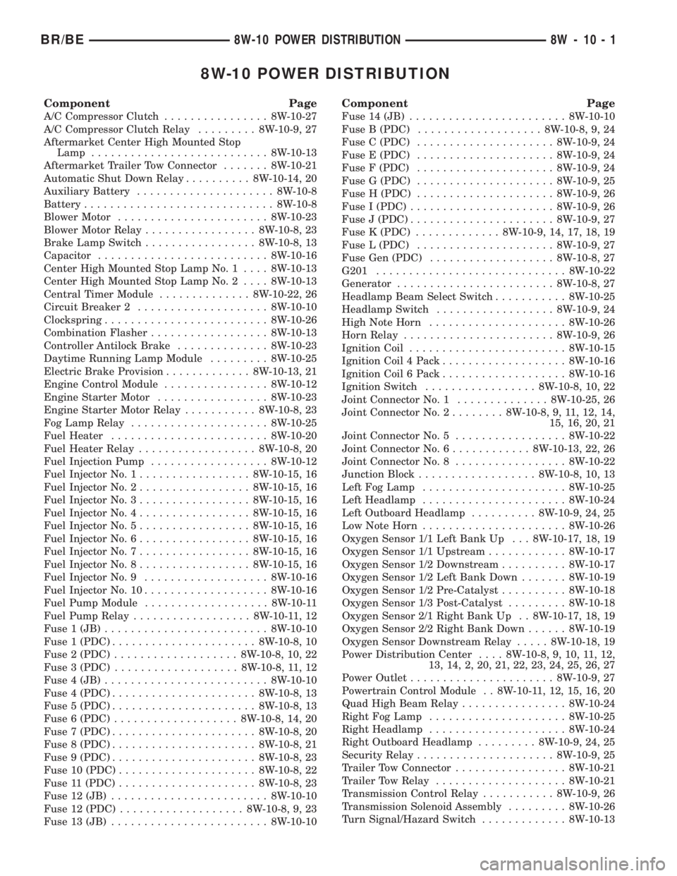
8W-10 POWER DISTRIBUTION
Component Page
A/C Compressor Clutch................ 8W-10-27
A/C Compressor Clutch Relay......... 8W-10-9, 27
Aftermarket Center High Mounted Stop
Lamp........................... 8W-10-13
Aftermarket Trailer Tow Connector....... 8W-10-21
Automatic Shut Down Relay.......... 8W-10-14, 20
Auxiliary Battery..................... 8W-10-8
Battery............................. 8W-10-8
Blower Motor....................... 8W-10-23
Blower Motor Relay................. 8W-10-8, 23
Brake Lamp Switch................. 8W-10-8, 13
Capacitor.......................... 8W-10-16
Center High Mounted Stop Lamp No. 1.... 8W-10-13
Center High Mounted Stop Lamp No. 2.... 8W-10-13
Central Timer Module.............. 8W-10-22, 26
Circuit Breaker 2.................... 8W-10-10
Clockspring......................... 8W-10-26
Combination Flasher.................. 8W-10-13
Controller Antilock Brake.............. 8W-10-23
Daytime Running Lamp Module......... 8W-10-25
Electric Brake Provision............. 8W-10-13, 21
Engine Control Module................ 8W-10-12
Engine Starter Motor................. 8W-10-23
Engine Starter Motor Relay........... 8W-10-8, 23
Fog Lamp Relay..................... 8W-10-25
Fuel Heater........................ 8W-10-20
Fuel Heater Relay.................. 8W-10-8, 20
Fuel Injection Pump.................. 8W-10-12
Fuel Injector No. 1................. 8W-10-15, 16
Fuel Injector No. 2................. 8W-10-15, 16
Fuel Injector No. 3................. 8W-10-15, 16
Fuel Injector No. 4................. 8W-10-15, 16
Fuel Injector No. 5................. 8W-10-15, 16
Fuel Injector No. 6................. 8W-10-15, 16
Fuel Injector No. 7................. 8W-10-15, 16
Fuel Injector No. 8................. 8W-10-15, 16
Fuel Injector No. 9................... 8W-10-16
Fuel Injector No. 10................... 8W-10-16
Fuel Pump Module................... 8W-10-11
Fuel Pump Relay.................. 8W-10-11, 12
Fuse 1 (JB)......................... 8W-10-10
Fuse 1 (PDC)...................... 8W-10-8, 10
Fuse 2 (PDC)................... 8W-10-8, 10, 22
Fuse 3 (PDC)................... 8W-10-8, 11, 12
Fuse 4 (JB)......................... 8W-10-10
Fuse 4 (PDC)...................... 8W-10-8, 13
Fuse 5 (PDC)...................... 8W-10-8, 13
Fuse 6 (PDC)................... 8W-10-8, 14, 20
Fuse 7 (PDC)...................... 8W-10-8, 20
Fuse 8 (PDC)...................... 8W-10-8, 21
Fuse 9 (PDC)...................... 8W-10-8, 23
Fuse 10 (PDC)..................... 8W-10-8, 22
Fuse 11 (PDC)..................... 8W-10-8, 23
Fuse 12 (JB)........................ 8W-10-10
Fuse 12 (PDC)................... 8W-10-8, 9, 23
Fuse 13 (JB)........................ 8W-10-10
Component Page
Fuse 14 (JB)........................ 8W-10-10
Fuse B (PDC)................... 8W-10-8, 9, 24
Fuse C (PDC)..................... 8W-10-9, 24
Fuse E (PDC)..................... 8W-10-9, 24
Fuse F (PDC)..................... 8W-10-9, 24
Fuse G (PDC)..................... 8W-10-9, 25
Fuse H (PDC)..................... 8W-10-9, 26
Fuse I (PDC)...................... 8W-10-9, 26
Fuse J (PDC)...................... 8W-10-9, 27
Fuse K (PDC)............. 8W-10-9, 14, 17, 18, 19
Fuse L (PDC)..................... 8W-10-9, 27
Fuse Gen (PDC)................... 8W-10-8, 27
G201............................. 8W-10-22
Generator........................ 8W-10-8, 27
Headlamp Beam Select Switch........... 8W-10-25
Headlamp Switch.................. 8W-10-9, 24
High Note Horn..................... 8W-10-26
Horn Relay....................... 8W-10-9, 26
Ignition Coil........................ 8W-10-15
Ignition Coil 4 Pack................... 8W-10-16
Ignition Coil 6 Pack................... 8W-10-16
Ignition Switch................. 8W-10-8, 10, 22
Joint Connector No. 1.............. 8W-10-25, 26
Joint Connector No. 2........ 8W-10-8, 9, 11, 12, 14,
15, 16, 20, 21
Joint Connector No. 5................. 8W-10-22
Joint Connector No. 6............ 8W-10-13, 22, 26
Joint Connector No. 8................. 8W-10-22
Junction Block.................. 8W-10-8, 10, 13
Left Fog Lamp...................... 8W-10-25
Left Headlamp...................... 8W-10-24
Left Outboard Headlamp.......... 8W-10-9, 24, 25
Low Note Horn...................... 8W-10-26
Oxygen Sensor 1/1 Left Bank Up . . . 8W-10-17, 18, 19
Oxygen Sensor 1/1 Upstream............ 8W-10-17
Oxygen Sensor 1/2 Downstream.......... 8W-10-17
Oxygen Sensor 1/2 Left Bank Down....... 8W-10-19
Oxygen Sensor 1/2 Pre-Catalyst.......... 8W-10-18
Oxygen Sensor 1/3 Post-Catalyst......... 8W-10-18
Oxygen Sensor 2/1 Right Bank Up . . 8W-10-17, 18, 19
Oxygen Sensor 2/2 Right Bank Down...... 8W-10-19
Oxygen Sensor Downstream Relay..... 8W-10-18, 19
Power Distribution Center.... 8W-10-8, 9, 10, 11, 12,
13, 14, 2, 20, 21, 22, 23, 24, 25, 26, 27
Power Outlet...................... 8W-10-9, 27
Powertrain Control Module . . 8W-10-11, 12, 15, 16, 20
Quad High Beam Relay................ 8W-10-24
Right Fog Lamp..................... 8W-10-25
Right Headlamp..................... 8W-10-24
Right Outboard Headlamp......... 8W-10-9, 24, 25
Security Relay..................... 8W-10-9, 25
Trailer Tow Connector................. 8W-10-21
Trailer Tow Relay.................... 8W-10-21
Transmission Control Relay........... 8W-10-9, 26
Transmission Solenoid Assembly......... 8W-10-26
Turn Signal/Hazard Switch............. 8W-10-13
BR/BE8W-10 POWER DISTRIBUTION 8W - 10 - 1
Page 760 of 2255
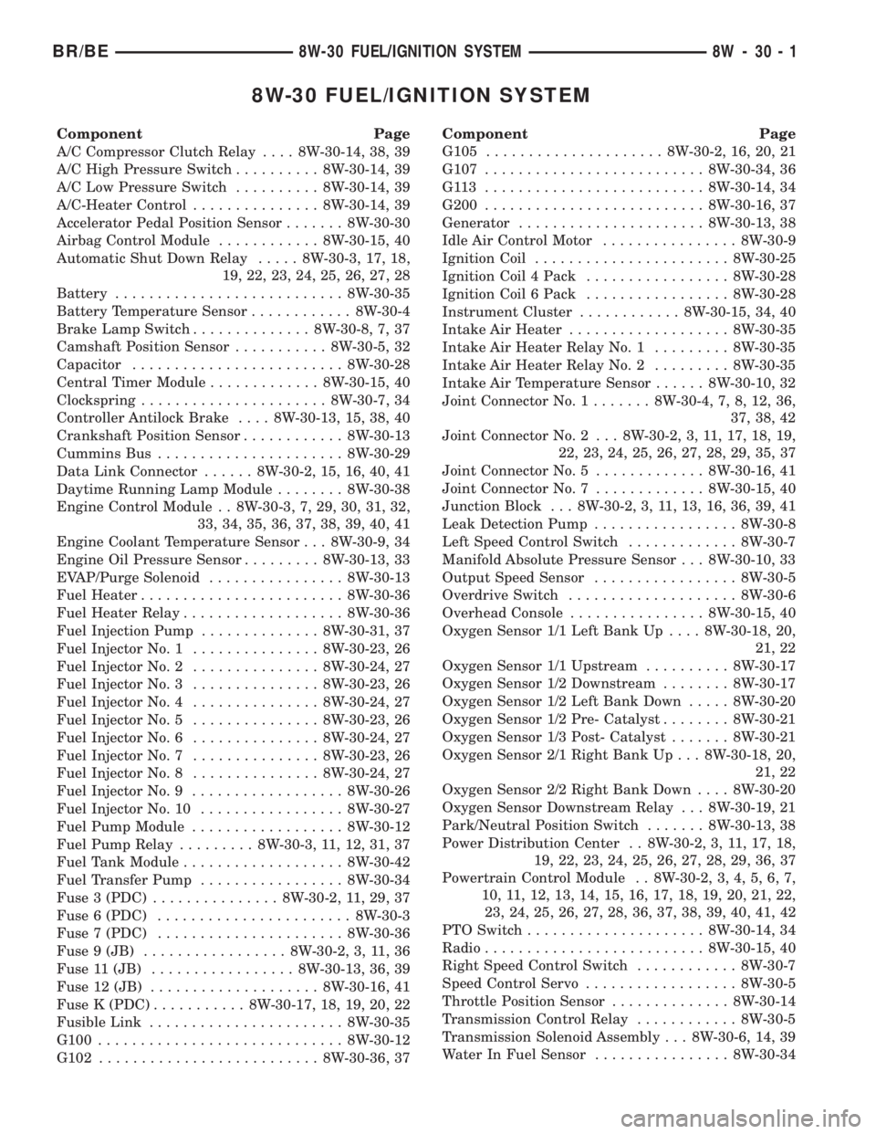
8W-30 FUEL/IGNITION SYSTEM
Component Page
A/C Compressor Clutch Relay.... 8W-30-14, 38, 39
A/C High Pressure Switch.......... 8W-30-14, 39
A/C Low Pressure Switch.......... 8W-30-14, 39
A/C-Heater Control............... 8W-30-14, 39
Accelerator Pedal Position Sensor....... 8W-30-30
Airbag Control Module............ 8W-30-15, 40
Automatic Shut Down Relay..... 8W-30-3, 17, 18,
19, 22, 23, 24, 25, 26, 27, 28
Battery........................... 8W-30-35
Battery Temperature Sensor............ 8W-30-4
Brake Lamp Switch.............. 8W-30-8, 7, 37
Camshaft Position Sensor........... 8W-30-5, 32
Capacitor......................... 8W-30-28
Central Timer Module............. 8W-30-15, 40
Clockspring...................... 8W-30-7, 34
Controller Antilock Brake.... 8W-30-13, 15, 38, 40
Crankshaft Position Sensor............ 8W-30-13
Cummins Bus...................... 8W-30-29
Data Link Connector...... 8W-30-2, 15, 16, 40, 41
Daytime Running Lamp Module........ 8W-30-38
Engine Control Module . . 8W-30-3, 7, 29, 30, 31, 32,
33, 34, 35, 36, 37, 38, 39, 40, 41
Engine Coolant Temperature Sensor . . . 8W-30-9, 34
Engine Oil Pressure Sensor......... 8W-30-13, 33
EVAP/Purge Solenoid................ 8W-30-13
Fuel Heater........................ 8W-30-36
Fuel Heater Relay................... 8W-30-36
Fuel Injection Pump.............. 8W-30-31, 37
Fuel Injector No. 1............... 8W-30-23, 26
Fuel Injector No. 2............... 8W-30-24, 27
Fuel Injector No. 3............... 8W-30-23, 26
Fuel Injector No. 4............... 8W-30-24, 27
Fuel Injector No. 5............... 8W-30-23, 26
Fuel Injector No. 6............... 8W-30-24, 27
Fuel Injector No. 7............... 8W-30-23, 26
Fuel Injector No. 8............... 8W-30-24, 27
Fuel Injector No. 9.................. 8W-30-26
Fuel Injector No. 10................. 8W-30-27
Fuel Pump Module.................. 8W-30-12
Fuel Pump Relay......... 8W-30-3, 11, 12, 31, 37
Fuel Tank Module................... 8W-30-42
Fuel Transfer Pump................. 8W-30-34
Fuse 3 (PDC)............... 8W-30-2, 11, 29, 37
Fuse 6 (PDC)....................... 8W-30-3
Fuse 7 (PDC)...................... 8W-30-36
Fuse 9 (JB)................. 8W-30-2, 3, 11, 36
Fuse 11 (JB)................. 8W-30-13, 36, 39
Fuse 12 (JB).................... 8W-30-16, 41
Fuse K (PDC)........... 8W-30-17, 18, 19, 20, 22
Fusible Link....................... 8W-30-35
G100............................. 8W-30-12
G102.......................... 8W-30-36, 37Component Page
G105..................... 8W-30-2, 16, 20, 21
G107.......................... 8W-30-34, 36
G113 .......................... 8W-30-14, 34
G200.......................... 8W-30-16, 37
Generator...................... 8W-30-13, 38
Idle Air Control Motor................ 8W-30-9
Ignition Coil....................... 8W-30-25
Ignition Coil 4 Pack................. 8W-30-28
Ignition Coil 6 Pack................. 8W-30-28
Instrument Cluster............ 8W-30-15, 34, 40
Intake Air Heater................... 8W-30-35
Intake Air Heater Relay No. 1......... 8W-30-35
Intake Air Heater Relay No. 2......... 8W-30-35
Intake Air Temperature Sensor...... 8W-30-10, 32
Joint Connector No. 1....... 8W-30-4, 7, 8, 12, 36,
37, 38, 42
Joint Connector No. 2 . . . 8W-30-2, 3, 11, 17, 18, 19,
22, 23, 24, 25, 26, 27, 28, 29, 35, 37
Joint Connector No. 5............. 8W-30-16, 41
Joint Connector No. 7............. 8W-30-15, 40
Junction Block . . . 8W-30-2, 3, 11, 13, 16, 36, 39, 41
Leak Detection Pump................. 8W-30-8
Left Speed Control Switch............. 8W-30-7
Manifold Absolute Pressure Sensor . . . 8W-30-10, 33
Output Speed Sensor................. 8W-30-5
Overdrive Switch.................... 8W-30-6
Overhead Console................ 8W-30-15, 40
Oxygen Sensor 1/1 Left Bank Up.... 8W-30-18, 20,
21, 22
Oxygen Sensor 1/1 Upstream.......... 8W-30-17
Oxygen Sensor 1/2 Downstream........ 8W-30-17
Oxygen Sensor 1/2 Left Bank Down..... 8W-30-20
Oxygen Sensor 1/2 Pre- Catalyst........ 8W-30-21
Oxygen Sensor 1/3 Post- Catalyst....... 8W-30-21
Oxygen Sensor 2/1 Right Bank Up . . . 8W-30-18, 20,
21, 22
Oxygen Sensor 2/2 Right Bank Down.... 8W-30-20
Oxygen Sensor Downstream Relay . . . 8W-30-19, 21
Park/Neutral Position Switch....... 8W-30-13, 38
Power Distribution Center . . 8W-30-2, 3, 11, 17, 18,
19, 22, 23, 24, 25, 26, 27, 28, 29, 36, 37
Powertrain Control Module . . 8W-30-2, 3, 4, 5, 6, 7,
10, 11, 12, 13, 14, 15, 16, 17, 18, 19, 20, 21, 22,
23, 24, 25, 26, 27, 28, 36, 37, 38, 39, 40, 41, 42
PTO Switch..................... 8W-30-14, 34
Radio.......................... 8W-30-15, 40
Right Speed Control Switch............ 8W-30-7
Speed Control Servo.................. 8W-30-5
Throttle Position Sensor.............. 8W-30-14
Transmission Control Relay............ 8W-30-5
Transmission Solenoid Assembly . . . 8W-30-6, 14, 39
Water In Fuel Sensor................ 8W-30-34
BR/BE8W-30 FUEL/IGNITION SYSTEM 8W - 30 - 1
Page 1007 of 2255
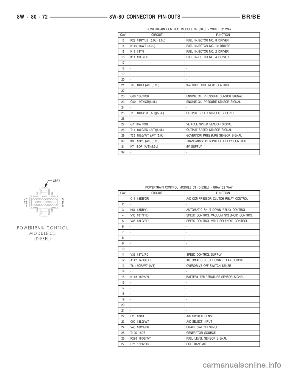
POWERTRAIN CONTROL MODULE C2 (GAS) - WHITE 32 WAY
CAV CIRCUIT FUNCTION
13 K28 18GY/LB (5.9L)(8.0L) FUEL INJECTOR NO. 8 DRIVER
14 K116 18WT (8.0L) FUEL INJECTOR NO. 10 DRIVER
15 K12 18TN FUEL INJECTOR NO. 2 DRIVER
16 K14 18LB/BR FUEL INJECTOR NO. 4 DRIVER
17 - -
18 - -
19 - -
20 - -
21 T60 18BR (A/T)(5.9L) 3-4 SHIFT SOLENOID CONTROL
22 - -
23 G60 18GY/OR ENGINE OIL PRESSURE SENSOR SIGNAL
23 G60 18GY/OR(5.9L) ENGINE OIL PRESURE SENSOR SIGNAL
24 - -
25 T13 18DB/BK (A/T)(5.9L) OUTPUT SPEED SENSOR GROUND
26 - -
27 G7 18WT/OR VEHICLE SPEED SENSOR SIGNAL
28 T14 18LG/BK (A/T)(5.9L) OUTPUT SPEED SENSOR SIGNAL
29 T25 18LG/WT (A/T)(5.9L) GOVERNOR PRESSURE SENSOR SIGNAL
30 K30 18PK (A/T)(5.9L) TRANSMISSION CONTROL RELAY CONTROL
31 K7 18OR (A/T)(5.9L) 5V SUPPLY
32 - -
POWERTRAIN CONTROL MODULE C3 (DIESEL) - GRAY 32 WAY
CAV CIRCUIT FUNCTION
1 C13 18DB/OR A/C COMPRESSOR CLUTCH RELAY CONTROL
2- -
3 K51 18DB/YL AUTOMATIC SHUT DOWN RELAY CONTROL
4 V36 18TN/RD SPEED CONTROL VACUUM SOLENOID CONTROL
5 V35 18LG/RD SPEED CONTROL VENT SOLENOID CONTROL
6- -
7- -
8- -
9- -
10 - -
11 V32 18YL/RD SPEED CONTROL SUPPLY
12 A142 14DG/OR AUTOMATIC SHUT DOWN RELAY OUTPUT
13 T6 18OR/WT (A/T) OVERDRIVE OFF SWITCH SENSE
14 - -
15 K118 18PK/YL BATTERY TEMPERATURE SENSOR SIGNAL
16 - -
17 - -
18 - -
19 - -
20 - -
21 - -
22 C20 18BR A/C SWITCH SENSE
23 C90 18LG/WT A/C SELECT INPUT
24 V40 18WT/PK BRAKE SWITCH SENSE
25 T125 18DB GENERATOR SOURCE
26 K226 18DB/WT FUEL LEVEL SENSOR SIGNAL
27 D21 18PK/DB SCI TRANSMIT
8W - 80 - 72 8W-80 CONNECTOR PIN-OUTSBR/BE
Page 1088 of 2255
(3) Lower engine into compartment and align
engine with transmission:
²Manual Transmission: Align clutch disc assem-
bly (if disturbed). Install transmission input shaft
into clutch disc while mating engine and transmis-
sion surfaces. Install two transmission to engine
block mounting bolts finger tight.
²Automatic Transmission: Mate engine and trans-
mission and install two transmission to engine block
mounting bolts finger tight.
(4) Lower engine assembly until engine mount
through bolts rest in mount perches.
(5) Install remaining transmission to engine block
mounting bolts and tighten.
(6) Tighten engine mount through bolts.
(7) Install drive plate to torque converter bolts.
(Automatic transmission models)
(8) Install the dust shield and transmission cover.
(9) Install the starter and connect the starter
wires (Refer to 8 - ELECTRICAL/STARTING/
STARTER MOTOR - INSTALLATION).
(10) Install exhaust pipe to manifold.
(11) Install the transmission cooler line brackets to
the oil pan.
(12) Install the drain plug and tighten to 34 N´m
(25 ft. lbs.) torque.
(13) Lower the vehicle.
(14) Remove engine lifting fixture.
(15) On Manual Transmission vehicles, install the
shift lever (Refer to 21 - TRANSMISSION/TRANS-
AXLE/MANUAL/SHIFT COVER - INSTALLATION).
(16) Connect the fuel supply line (Refer to 14 -
FUEL SYSTEM/FUEL DELIVERY/QUICK CON-
NECT FITTING - STANDARD PROCEDURE).
(17) Connect the power steering hoses, if equipped.
(18) Connect the heater hoses.
(19) Install the distributor cap and wiring.
(20) Install the intake manifold (Refer to 9 -
ENGINE/MANIFOLDS/INTAKE MANIFOLD -
INSTALLATION).
(21) Using a new gasket, install throttle body
(Refer to 14 - FUEL SYSTEM/FUEL INJECTION/
THROTTLE BODY - INSTALLATION).
(22) Connect the throttle linkage (Refer to 14 -
FUEL SYSTEM/FUEL INJECTION/THROTTLE
CONTROL CABLE - INSTALLATION).
(23) Install the air cleaner resonator and duct
work..
(24) Install the generator and wire connections
(Refer to 8 - ELECTRICAL/CHARGING/GENERA-
TOR - INSTALLATION).
(25) Install a/c compressor and lines (Refer to 24 -
HEATING & AIR CONDITIONING/PLUMBING/A/C
COMPRESSOR - INSTALLATION).(26) Install the accessory drive belt (Refer to 7 -
COOLING/ACCESSORY DRIVE/DRIVE BELTS -
INSTALLATION).
(27) Install upper radiator support crossmember.
(28) Install radiator (Refer to 7 - COOLING/EN-
GINE/RADIATOR - INSTALLATION).
(29) Connect the radiator lower hose.
(30) Connect the transmission oil cooler lines to
the radiator.
(31) Install the fan shroud.
(32) Install the fan (Refer to 7 - COOLING/EN-
GINE/RADIATOR FAN - INSTALLATION).
(33) Connect the radiator upper hose.
(34) Install the washer bottle.
(35) Install the transmission oil cooler (Refer to 7 -
COOLING/TRANSMISSION/TRANS COOLER -
INSTALLATION).
(36) Connect the transmission cooler lines.
(37) If equipped, install the condenser (Refer to 24
- HEATING & AIR CONDITIONING/PLUMBING/
A/C CONDENSER - INSTALLATION).
(38) Evacuate and charge the air conditioning sys-
tem, if equipped (Refer to 24 - HEATING & AIR
CONDITIONING/PLUMBING - STANDARD PRO-
CEDURE).
(39) Add engine oil to crankcase (Refer to LUBRI-
CATION & MAINTENANCE/FLUID TYPES - SPEC-
IFICATIONS).
(40) Fill cooling system (Refer to 7 - COOLING -
STANDARD PROCEDURE).
(41) Connect battery negative cable.
(42) Start engine and inspect for leaks.
(43) Road test vehicle.
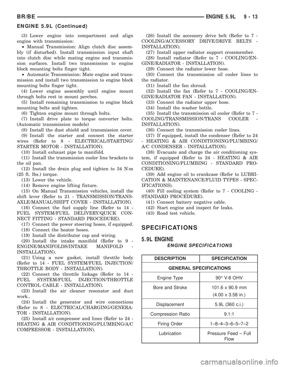
SPECIFICATIONS
5.9L ENGINE
ENGINE SPECIFICATIONS
DESCRIPTION SPECIFICATION
GENERAL SPECIFICATIONS
Engine Type 90É V-8 OHV
Bore and Stroke 101.6 x 90.9 mm
(4.00 x 3.58 in.)
Displacement 5.9L (360 c.i.)
Compression Ratio 9.1:1
Firing Order 1±8±4±3±6±5±7±2
Lubrication Pressure Feed ± Full
Flow
BR/BEENGINE 5.9L 9 - 13
ENGINE 5.9L (Continued)
Page 1093 of 2255
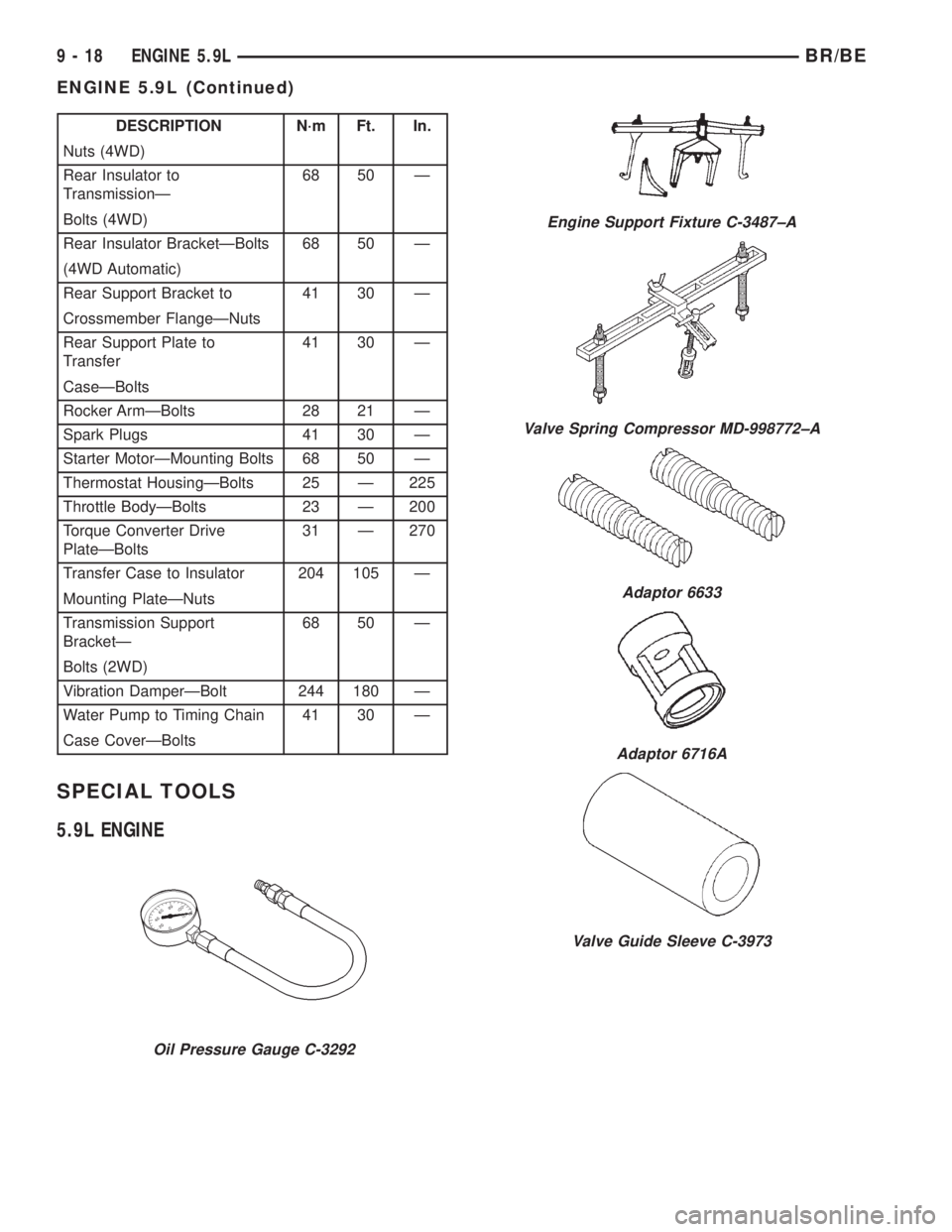
DESCRIPTION N´m Ft. In.
Nuts (4WD)
Rear Insulator to
TransmissionÐ68 50 Ð
Bolts (4WD)
Rear Insulator BracketÐBolts 68 50 Ð
(4WD Automatic)
Rear Support Bracket to 41 30 Ð
Crossmember FlangeÐNuts
Rear Support Plate to
Transfer41 30 Ð
CaseÐBolts
Rocker ArmÐBolts 28 21 Ð
Spark Plugs 41 30 Ð
Starter MotorÐMounting Bolts 68 50 Ð
Thermostat HousingÐBolts 25 Ð 225
Throttle BodyÐBolts 23 Ð 200
Torque Converter Drive
PlateÐBolts31 Ð 270
Transfer Case to Insulator 204 105 Ð
Mounting PlateÐNuts
Transmission Support
BracketÐ68 50 Ð
Bolts (2WD)
Vibration DamperÐBolt 244 180 Ð
Water Pump to Timing Chain 41 30 Ð
Case CoverÐBolts
SPECIAL TOOLS
5.9L ENGINE
Oil Pressure Gauge C-3292
Engine Support Fixture C-3487±A
Valve Spring Compressor MD-998772±A
Adaptor 6633
Adaptor 6716A
Valve Guide Sleeve C-3973
9 - 18 ENGINE 5.9LBR/BE
ENGINE 5.9L (Continued)
Page 1198 of 2255
(1) Disconnect the negative cable(s) from the bat-
tery.
(2) Inspect air cleaner, induction system, and
intake manifold to ensure system is dry and clear of
foreign material.
(3) Place a shop towel around the fuel injectors to
catch any fluid that may possibly be under pressure
in the cylinder head. Remove the fuel injectors (Refer
to 14 - FUEL SYSTEM/FUEL INJECTION/FUEL
INJECTOR - REMOVAL).
(4) With all injectors removed, rotate the crank-
shaft using a breaker bar and socket.
(5) Identify the fluid in the cylinders (coolant, fuel,
oil, etc.).
(6) Be sure all fluid has been removed from the
cylinders.
(7) Repair engine or components as necessary to
prevent this problem from occurring again.
(8) Squirt a small amount of engine oil into the
cylinders to lubricate the walls. This will prevent
damage on restart.
(9) Install new fuel injectors (Refer to 14 - FUEL
SYSTEM/FUEL INJECTION/FUEL INJECTOR -
INSTALLATION).
(10) Drain engine oil. Remove and discard the oil
filter (Refer to 9 - ENGINE/LUBRICATION/OIL FIL-
TER - REMOVAL).
(11) Install the drain plug. Tighten the plug to 34
N´m (25 ft. lbs.) torque.
(12) Install a new oil filter (Refer to 9 - ENGINE/
LUBRICATION/OIL FILTER - INSTALLATION).
(13) Fill engine crankcase with the specified
amount and grade of oil (Refer to LUBRICATION &
MAINTENANCE/FLUID TYPES - SPECIFICA-
TIONS).
(14) Connect the negative cable(s) to the battery.
(15) Start the engine and check for any leaks.
REMOVAL
REMOVALÐENGINE
(1) Disconnect both battery negative cables.
(2) Recover A/C refrigerant (if A/C equipped) (Refer
to 24 - HEATING & AIR CONDITIONING/PLUMB-
ING - STANDARD PROCEDURE).
(3) Raise vehicle on hoist.
(4) Drain engine coolant (Refer to 7 - COOLING -
STANDARD PROCEDURE).
(5) Remove engine oil drain plug and drain engine
oil.
(6) Lower vehicle.
(7) Remove radiator upper hose.
(8) Remove the cooling fan shroud-to-radiator
mounting bolts.(9) Remove viscous fan/drive assembly (Refer to 7 -
COOLING/ENGINE/RADIATOR FAN - REMOVAL).
Remove the cooling fan and shroud together.
(10) Disconnect the coolant recovery bottle hose
from the radiator filler neck and remove bottle from
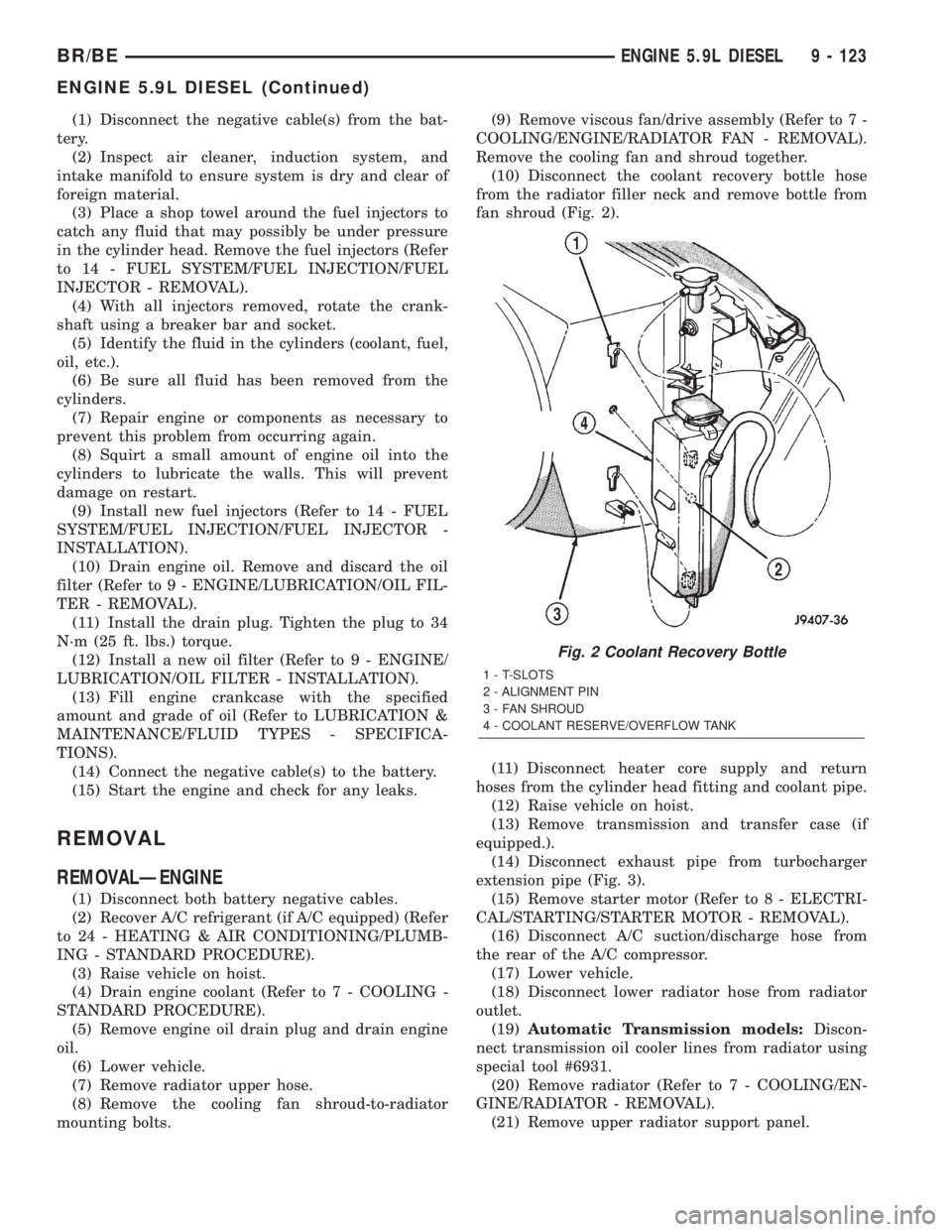
fan shroud (Fig. 2).
(11) Disconnect heater core supply and return
hoses from the cylinder head fitting and coolant pipe.
(12) Raise vehicle on hoist.
(13) Remove transmission and transfer case (if
equipped.).
(14) Disconnect exhaust pipe from turbocharger
extension pipe (Fig. 3).
(15) Remove starter motor (Refer to 8 - ELECTRI-
CAL/STARTING/STARTER MOTOR - REMOVAL).
(16) Disconnect A/C suction/discharge hose from
the rear of the A/C compressor.
(17) Lower vehicle.
(18) Disconnect lower radiator hose from radiator
outlet.
(19)Automatic Transmission models:Discon-
nect transmission oil cooler lines from radiator using
special tool #6931.
(20) Remove radiator (Refer to 7 - COOLING/EN-
GINE/RADIATOR - REMOVAL).
(21) Remove upper radiator support panel.
Fig. 2 Coolant Recovery Bottle
1 - T-SLOTS
2 - ALIGNMENT PIN
3 - FAN SHROUD
4 - COOLANT RESERVE/OVERFLOW TANK
BR/BEENGINE 5.9L DIESEL 9 - 123
ENGINE 5.9L DIESEL (Continued)
Page 1228 of 2255
(5) Lower vehicle.
(6) Remove radiator upper hose.
(7) Remove viscous fan/drive assembly and fan
shroud (Refer to 7 - COOLING/ENGINE/RADIATOR
FAN - REMOVAL).
(8) Disconnect the coolant recovery bottle hose
from the radiator filler neck.
(9) Disconnect lower radiator hose from radiator
outlet.
(10)Automatic Transmission models:Discon-
nect transmission oil cooler lines from radiator using
Special Tool 6931 (unless equipped with finger-re-
lease disconnect).
(11) Remove radiator mounting screws and lift
radiator out of engine compartment.
(12) Remove upper radiator support panel.
(13) Remove front bumper assembly (Refer to 13 -
FRAMES & BUMPERS/BUMPERS/FRONT
BUMPER - REMOVAL).
(14) If A/C equipped, disconnect A/C condenser
refrigerant lines.
(15) Disconnect charge air cooler piping from the
cooler inlet and outlet.
(16) Remove the two charge air cooler mounting
bolts.
(17) Remove charge air cooler (and A/C condenser
if equipped) from vehicle.
(18) Remove accessory drive belt (Refer to 7 -
COOLING/ACCESSORY DRIVE/DRIVE BELTS -
REMOVAL).
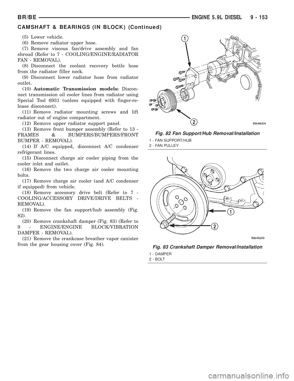
(19) Remove the fan support/hub assembly (Fig.
82).
(20) Remove crankshaft damper (Fig. 83) (Refer to
9 - ENGINE/ENGINE BLOCK/VIBRATION
DAMPER - REMOVAL).
(21) Remove the crankcase breather vapor canister
from the gear housing cover (Fig. 84).
Fig. 82 Fan Support/Hub Removal/Installation
1 - FAN SUPPORT/HUB
2 - FAN PULLEY
Fig. 83 Crankshaft Damper Removal/Installation
1 - DAMPER
2 - BOLT
BR/BEENGINE 5.9L DIESEL 9 - 153
CAMSHAFT & BEARINGS (IN BLOCK) (Continued)
Page 1330 of 2255
(22) Inspect for pinched or leaking fuel tubes.
Inspect for pinched, cracked or leaking fuel hoses.
(23) Inspect for exhaust system restrictions such
as pinched exhaust pipes, collapsed muffler or
plugged catalytic convertor.
(24) If equipped with automatic transmission, ver-
ify that electrical harness is firmly connected to park/
neutral switch. Refer to 21, Automatic Transmission.(25) Verify electrical harness is firmly connected to
rear wheel speed sensor. Verify rear wheel speed sen-
sor is firmly attached to rear axle with proper air
gap. Refer to 5, Brakes for information.
(26) If equipped with 4±wheel antilock brake sys-
tem, verify electrical harness is firmly connected to
each front wheel speed sensor. Verify both front
wheel speed sensors are firmly attached. Refer to 5,
Brakes for information.
(27) Verify that fuel pump/gauge sender unit wire
connector is firmly connected to harness connector.
(28) Inspect fuel hoses at fuel pump/gauge sender
unit for cracks or leaks.
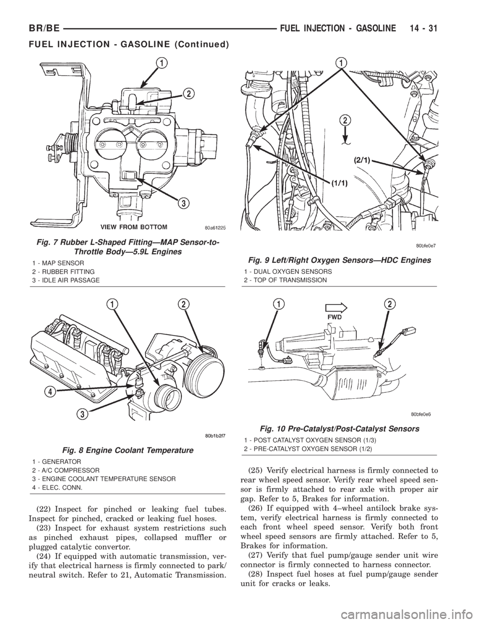
Fig. 7 Rubber L-Shaped FittingÐMAP Sensor-to-
Throttle BodyÐ5.9L Engines
1 - MAP SENSOR
2 - RUBBER FITTING
3 - IDLE AIR PASSAGE
Fig. 8 Engine Coolant Temperature
1 - GENERATOR
2 - A/C COMPRESSOR
3 - ENGINE COOLANT TEMPERATURE SENSOR
4 - ELEC. CONN.
Fig. 9 Left/Right Oxygen SensorsÐHDC Engines
1 - DUAL OXYGEN SENSORS
2 - TOP OF TRANSMISSION
Fig. 10 Pre-Catalyst/Post-Catalyst Sensors
1 - POST CATALYST OXYGEN SENSOR (1/3)
2 - PRE-CATALYST OXYGEN SENSOR (1/2)
BR/BEFUEL INJECTION - GASOLINE 14 - 31
FUEL INJECTION - GASOLINE (Continued)