2002 DODGE RAM automatic transmission
[x] Cancel search: automatic transmissionPage 427 of 2255
the feed of battery voltage to the starter motor, also
engaging and disengaging the starter pinion gear
with the starter ring gear.
All starter motors use an overrunning clutch and
starter pinion gear unit to engage and drive a starter
ring gear that is integral to the flywheel (manual
transmission), torque converter or torque converter
drive plate (automatic transmission) mounted on the
rear crankshaft flange.
DIAGNOSIS AND TESTING - STARTER MOTOR
Correct starter motor operation can be confirmed
by performing the following free running bench test.
This test can only be performed with starter motor
removed from vehicle. Refer to Starter Specifications
for starter motor specifications.
(1) Remove starter motor from vehicle. Refer to
Starter MotorRemoval and Installation.
(2) Mount starter motor securely in a soft-jawed
bench vise. The vise jaws should be clamped on
mounting flange of starter motor. Never clamp on
starter motor by field frame.
(3) Connect suitable volt-ampere tester and 12-volt
battery to starter motor in series, and set ammeter to
100 ampere scale (250 ampere scale for diesel engine
starters). See instructions provided by manufacturer
of volt-ampere tester being used.
(4) Install jumper wire from solenoid terminal to
solenoid battery terminal. The starter motor should
operate. If starter motor fails to operate, replace
faulty starter motor assembly.
(5) Adjust carbon pile load of tester to obtain free
running test voltage. Refer to Specifications for the
starter motor free running test voltage specifications.
(6) Note reading on ammeter and compare this
reading to free running test maximum amperage
draw. Refer to Specifications for starter motor free
running test maximum amperage draw specifica-
tions.
(7) If ammeter reading exceeds maximum amper-
age draw specification, replace faulty starter motor
assembly.
STARTER MOTOR SOLENOID
This test can only be performed with starter motor
removed from vehicle.
(1) Remove starter motor. Refer toStarter Motor
Removal and Installation.
(2) Disconnect wire from solenoid field coil termi-
nal.
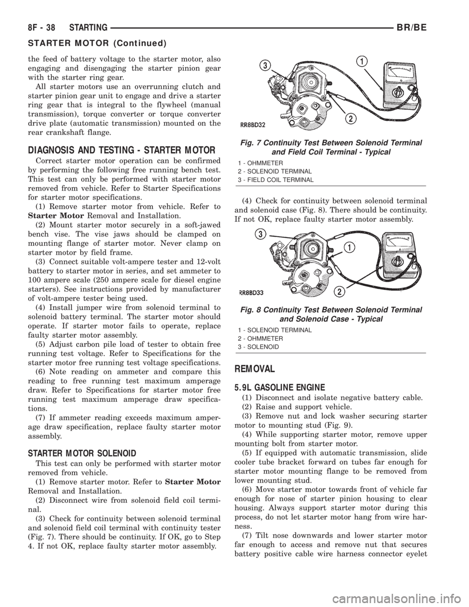
(3) Check for continuity between solenoid terminal
and solenoid field coil terminal with continuity tester
(Fig. 7). There should be continuity. If OK, go to Step
4. If not OK, replace faulty starter motor assembly.(4) Check for continuity between solenoid terminal
and solenoid case (Fig. 8). There should be continuity.
If not OK, replace faulty starter motor assembly.
REMOVAL
5.9L GASOLINE ENGINE
(1) Disconnect and isolate negative battery cable.
(2) Raise and support vehicle.
(3) Remove nut and lock washer securing starter
motor to mounting stud (Fig. 9).
(4) While supporting starter motor, remove upper
mounting bolt from starter motor.
(5) If equipped with automatic transmission, slide
cooler tube bracket forward on tubes far enough for
starter motor mounting flange to be removed from
lower mounting stud.
(6) Move starter motor towards front of vehicle far
enough for nose of starter pinion housing to clear
housing. Always support starter motor during this
process, do not let starter motor hang from wire har-
ness.
(7) Tilt nose downwards and lower starter motor
far enough to access and remove nut that secures
battery positive cable wire harness connector eyelet
Fig. 7 Continuity Test Between Solenoid Terminal
and Field Coil Terminal - Typical
1 - OHMMETER
2 - SOLENOID TERMINAL
3 - FIELD COIL TERMINAL
Fig. 8 Continuity Test Between Solenoid Terminal
and Solenoid Case - Typical
1 - SOLENOID TERMINAL
2 - OHMMETER
3 - SOLENOID
8F - 38 STARTINGBR/BE
STARTER MOTOR (Continued)
Page 429 of 2255
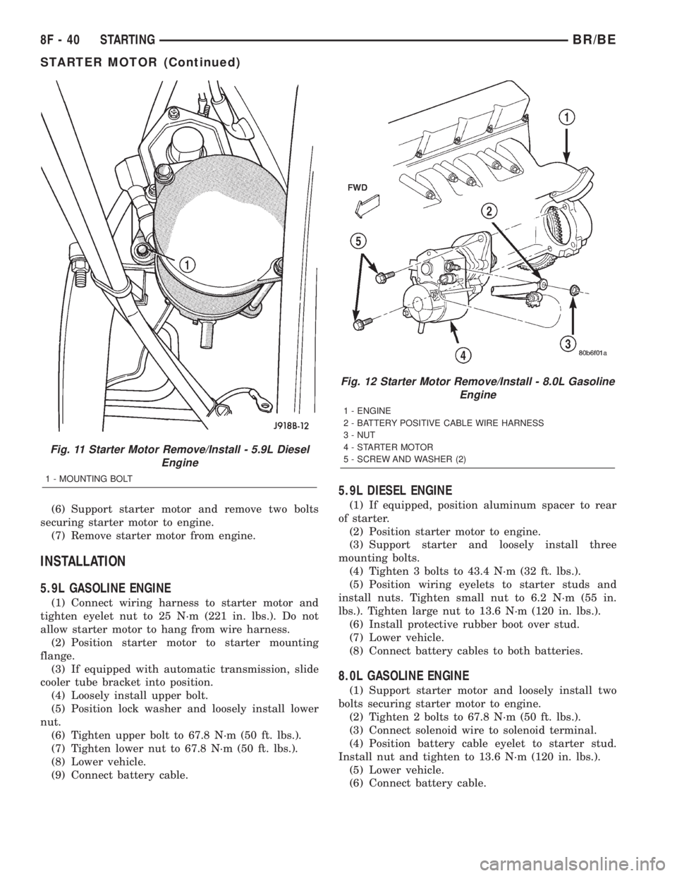
(6) Support starter motor and remove two bolts
securing starter motor to engine.
(7) Remove starter motor from engine.
INSTALLATION
5.9L GASOLINE ENGINE
(1) Connect wiring harness to starter motor and
tighten eyelet nut to 25 N´m (221 in. lbs.). Do not
allow starter motor to hang from wire harness.
(2) Position starter motor to starter mounting
flange.
(3) If equipped with automatic transmission, slide
cooler tube bracket into position.
(4) Loosely install upper bolt.
(5) Position lock washer and loosely install lower
nut.
(6) Tighten upper bolt to 67.8 N´m (50 ft. lbs.).
(7) Tighten lower nut to 67.8 N´m (50 ft. lbs.).
(8) Lower vehicle.
(9) Connect battery cable.
5.9L DIESEL ENGINE
(1) If equipped, position aluminum spacer to rear
of starter.
(2) Position starter motor to engine.
(3) Support starter and loosely install three
mounting bolts.
(4) Tighten 3 bolts to 43.4 N´m (32 ft. lbs.).
(5) Position wiring eyelets to starter studs and
install nuts. Tighten small nut to 6.2 N´m (55 in.
lbs.). Tighten large nut to 13.6 N´m (120 in. lbs.).
(6) Install protective rubber boot over stud.
(7) Lower vehicle.
(8) Connect battery cables to both batteries.
8.0L GASOLINE ENGINE
(1) Support starter motor and loosely install two
bolts securing starter motor to engine.
(2) Tighten 2 bolts to 67.8 N´m (50 ft. lbs.).
(3) Connect solenoid wire to solenoid terminal.
(4) Position battery cable eyelet to starter stud.
Install nut and tighten to 13.6 N´m (120 in. lbs.).
(5) Lower vehicle.
(6) Connect battery cable.
Fig. 11 Starter Motor Remove/Install - 5.9L Diesel
Engine
1 - MOUNTING BOLT
Fig. 12 Starter Motor Remove/Install - 8.0L Gasoline
Engine
1 - ENGINE
2 - BATTERY POSITIVE CABLE WIRE HARNESS
3 - NUT
4 - STARTER MOTOR
5 - SCREW AND WASHER (2)
8F - 40 STARTINGBR/BE
STARTER MOTOR (Continued)
Page 430 of 2255
STARTER MOTOR RELAY
DESCRIPTION
The starter relay is an electromechanical device
that switches battery current to the pull-in coil of the
starter solenoid when ignition switch is turned to
Start position. The starter relay is located in the
Power Distribution Center (PDC) in the engine com-
partment. See PDC cover for relay identification and
location.
The starter relay is a International Standards
Organization (ISO) relay. Relays conforming to ISO
specifications have common physical dimensions, cur-
rent capacities, terminal patterns, and terminal func-
tions.
The starter relay cannot be repaired or adjusted
and, if faulty or damaged, it must be replaced.
OPERATION
The ISO relay consists of an electromagnetic coil, a
resistor or diode, and three (two fixed and one mov-
able) electrical contacts. The movable (common feed)
relay contact is held against one of the fixed contacts
(normally closed) by spring pressure. When electro-
magnetic coil is energized, it draws the movable con-
tact away from normally closed fixed contact, and
holds it against the other (normally open) fixed con-
tact.
When electromagnetic coil is de-energized, spring
pressure returns movable contact to normally closed
position. The resistor or diode is connected in parallel
with electromagnetic coil within relay, and helps to
dissipate voltage spikes produced when coil is de-en-
ergized.
DIAGNOSIS AND TESTING - STARTER RELAY
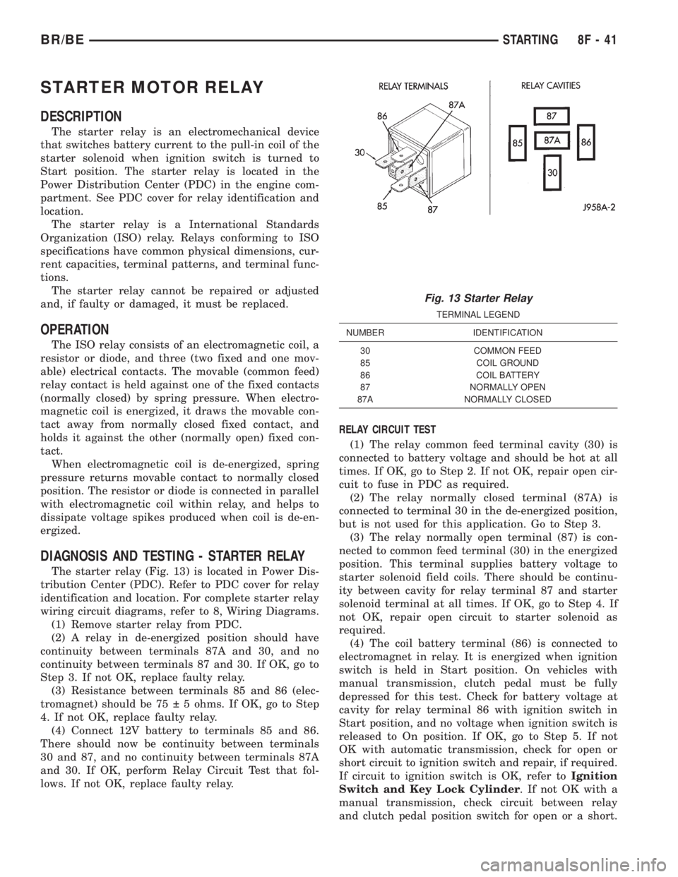
The starter relay (Fig. 13) is located in Power Dis-
tribution Center (PDC). Refer to PDC cover for relay
identification and location. For complete starter relay
wiring circuit diagrams, refer to 8, Wiring Diagrams.
(1) Remove starter relay from PDC.
(2) A relay in de-energized position should have
continuity between terminals 87A and 30, and no
continuity between terminals 87 and 30. If OK, go to
Step 3. If not OK, replace faulty relay.
(3) Resistance between terminals 85 and 86 (elec-
tromagnet) should be 75 5 ohms. If OK, go to Step
4. If not OK, replace faulty relay.
(4) Connect 12V battery to terminals 85 and 86.
There should now be continuity between terminals
30 and 87, and no continuity between terminals 87A
and 30. If OK, perform Relay Circuit Test that fol-
lows. If not OK, replace faulty relay.RELAY CIRCUIT TEST
(1) The relay common feed terminal cavity (30) is
connected to battery voltage and should be hot at all
times. If OK, go to Step 2. If not OK, repair open cir-
cuit to fuse in PDC as required.
(2) The relay normally closed terminal (87A) is
connected to terminal 30 in the de-energized position,
but is not used for this application. Go to Step 3.
(3) The relay normally open terminal (87) is con-
nected to common feed terminal (30) in the energized
position. This terminal supplies battery voltage to
starter solenoid field coils. There should be continu-
ity between cavity for relay terminal 87 and starter
solenoid terminal at all times. If OK, go to Step 4. If
not OK, repair open circuit to starter solenoid as
required.
(4) The coil battery terminal (86) is connected to
electromagnet in relay. It is energized when ignition
switch is held in Start position. On vehicles with
manual transmission, clutch pedal must be fully
depressed for this test. Check for battery voltage at
cavity for relay terminal 86 with ignition switch in
Start position, and no voltage when ignition switch is
released to On position. If OK, go to Step 5. If not
OK with automatic transmission, check for open or
short circuit to ignition switch and repair, if required.
If circuit to ignition switch is OK, refer toIgnition
Switch and Key Lock Cylinder. If not OK with a
manual transmission, check circuit between relay
and clutch pedal position switch for open or a short.
Fig. 13 Starter Relay
TERMINAL LEGEND
NUMBER IDENTIFICATION
30 COMMON FEED
85 COIL GROUND
86 COIL BATTERY
87 NORMALLY OPEN
87A NORMALLY CLOSED
BR/BESTARTING 8F - 41
Page 431 of 2255
If circuit is OK, refer toClutch Pedal Position
Switchin 6 , Clutch.
(5) The coil ground terminal (85) is connected to
the electromagnet in the relay. On vehicles with
manual transmission, it is grounded at all times. On
vehicles with automatic transmission, it is grounded
through park/neutral position switch only when gear-
shift selector lever is in Park or Neutral positions.
Check for continuity to ground at cavity for relay ter-
minal 85. If not OK with manual transmission,
repair circuit to ground as required. If not OK with
automatic transmission, check for pen or short circuit
to park/neutral position switch and repair, if
required. If circuit to park/neutral position switch is
OK, refer toPark/Neutral Position Switchin 21,
Transmission.
REMOVAL
(1) Disconnect and isolate negative battery cable
(both negative cables if diesel).
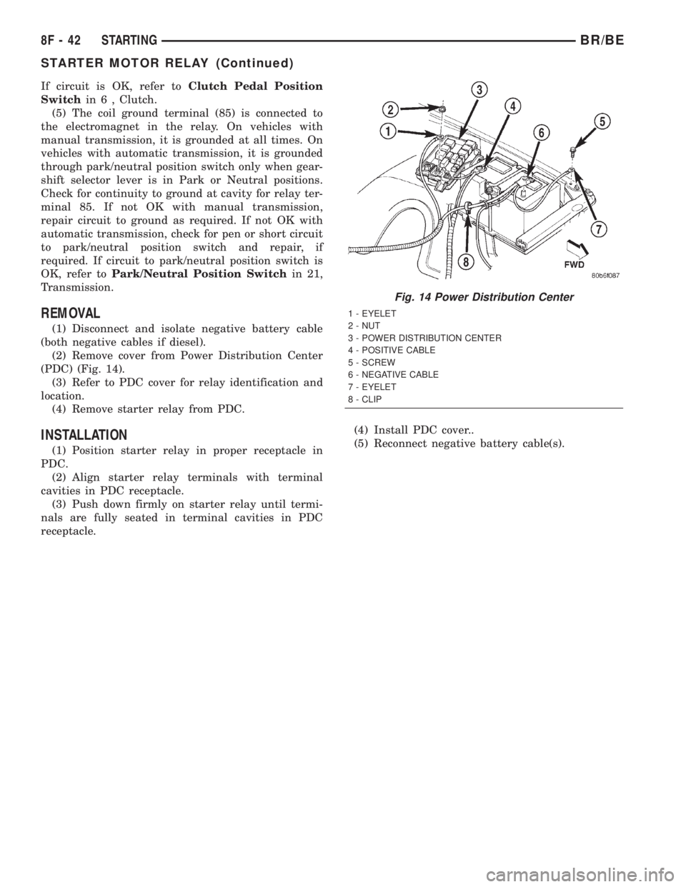
(2) Remove cover from Power Distribution Center
(PDC) (Fig. 14).
(3) Refer to PDC cover for relay identification and
location.
(4) Remove starter relay from PDC.
INSTALLATION
(1) Position starter relay in proper receptacle in
PDC.
(2) Align starter relay terminals with terminal
cavities in PDC receptacle.
(3) Push down firmly on starter relay until termi-
nals are fully seated in terminal cavities in PDC
receptacle.(4) Install PDC cover..
(5) Reconnect negative battery cable(s).
Fig. 14 Power Distribution Center
1 - EYELET
2 - NUT
3 - POWER DISTRIBUTION CENTER
4 - POSITIVE CABLE
5 - SCREW
6 - NEGATIVE CABLE
7 - EYELET
8 - CLIP
8F - 42 STARTINGBR/BE
STARTER MOTOR RELAY (Continued)
Page 482 of 2255

²Check Gauges Indicator
²Cruise Indicator (Odometer VFD)
²Four-Wheel Drive Indicator
²High Beam Indicator
²Low Fuel Indicator
²Washer Fluid Indicator
²Malfunction Indicator Lamp (MIL)
²Overdrive-Off Indicator
²Seatbelt Indicator
²Service Reminder Indicator (SRI)
²Transmission Overtemp Indicator
²Turn Signal (Right and Left) Indicators
²Upshift Indicator
²Wait-To-Start Indicator (Diesel Only)
²Water-In-Fuel Indicator (Diesel Only)
Some of these indicators are either programmable
or automatically configured when the EMIC is con-
nected to the vehicle electrical system. This feature
allows those indicators to be activated or deactivated
for compatibility with certain optional equipment.
The EMIC also includes a provision for mounting the
automatic transmission gear selector indicator in the
lower right corner of the cluster. The spring-loaded,
cable driven, mechanical gear selector indicator gives
an indication of the transmission gear that has been
selected with the automatic transmission gear selec-
tor lever. The gear selector indicator pointer is easily
visible through an opening provided in the front of
the cluster overlay, and is also lighted by the cluster
illumination lamps for visibility at night. Models
equipped with a manual transmission have a block-
out plate installed in place of the gear selector indi-
cator.
Cluster illumination is accomplished by adjustable
incandescent back lighting, which illuminates the
gauges for visibility when the exterior lighting is
turned on. The EMIC high beam indicator, turn sig-
nal indicators, and wait-to-start indicator are also
illuminated by dedicated incandescent bulbs. The
remaining indicators in the EMIC are each illumi-
nated by a dedicated Light Emitting Diode (LED)
that is soldered onto the electronic circuit board.
Each of the incandescent bulbs is secured by an inte-
gral bulb holder to the electronic circuit board from
the back of the cluster housing.
Hard wired circuitry connects the EMIC to the
electrical system of the vehicle. These hard wired cir-
cuits are integral to several wire harnesses, which
are routed throughout the vehicle and retained by
many different methods. These circuits may be con-
nected to each other, to the vehicle electrical system
and to the EMIC through the use of a combination of
soldered splices, splice block connectors, and many
different types of wire harness terminal connectors
and insulators. Refer to the appropriate wiring infor-
mation. The wiring information includes wiring dia-grams, proper wire and connector repair procedures,
further details on wire harness routing and reten-
tion, as well as pin-out and location views for the
various wire harness connectors, splices and grounds.
The EMIC modules for this model are serviced only
as complete units. The EMIC module cannot be
adjusted or repaired. If a gauge, an LED indicator,
the VFD, the electronic circuit board, the circuit
board hardware, the cluster overlay, or the EMIC
housing are damaged or faulty, the entire EMIC mod-
ule must be replaced. The cluster lens and hood unit,
the rear cluster housing cover, the automatic trans-
mission gear selector indicator, and the incandescent
lamp bulbs with holders are available for individual
service replacement.
OPERATION
The ElectroMechanical Instrument Cluster (EMIC)
is designed to allow the vehicle operator to monitor
the conditions of many of the vehicle components and
operating systems. The gauges and indicators in the
EMIC provide valuable information about the various
standard and optional powertrains, fuel and emis-
sions systems, cooling systems, lighting systems,
safety systems and many other convenience items.
The EMIC is installed in the instrument panel so
that all of these monitors can be easily viewed by the
vehicle operator when driving, while still allowing
relative ease of access for service. The microproces-
sor-based EMIC hardware and software uses various
inputs to control the gauges and indicators visible on
the face of the cluster. Some of these inputs are hard
wired, but most are in the form of electronic mes-
sages that are transmitted by other electronic mod-
ules over the Chrysler Collision Detection (CCD) data
bus network. (Refer to 8 - ELECTRICAL/ELEC-
TRONIC CONTROL MODULES/COMMUNICATION
- OPERATION).
The EMIC microprocessor smooths the input data
using algorithms to provide gauge readings that are
accurate, stable and responsive to operating condi-
tions. These algorithms are designed to provide
gauge readings during normal operation that are con-
sistent with customer expectations. However, when
abnormal conditions exist, such as low/high battery
voltage, low oil pressure, or high coolant tempera-
ture, the algorithm drives the gauge pointer to an
extreme position and the microprocessor turns on the
Check Gauges indicator to provide a distinct visual
indication of a problem to the vehicle operator. The
instrument cluster circuitry may also generate a
hard wired chime tone request to the Central Timer
Module (CTM) when it monitors certain conditions or
inputs, in order to provide the vehicle operator with
an audible alert.
BR/BEINSTRUMENT CLUSTER 8J - 3
INSTRUMENT CLUSTER (Continued)
Page 484 of 2255

trol some of the VFD functions requires the use of a
DRBIIItscan tool. Refer to the appropriate diagnos-
tic information. Specific operation details for the
odometer and trip odometer functions of the VFD
may be found elsewhere in this service manual.
INDICATORS
Indicators are located in various positions within
the EMIC and are all connected to the EMIC circuit
board. The four-wheel drive indicator, high beam
indicator, washer fluid indicator, turn signal indica-
tors, and wait-to-start indicator are hard wired. The
brake indicator is controlled by CCD data bus mes-
sages from the Controller Anti-lock Brake (CAB) and
the hard wired park brake switch input to the EMIC.
The seatbelt indicator is controlled by the EMIC pro-
gramming, CCD data bus messages from the Airbag
Control Module (ACM), and the hard wired seat belt
switch input to the EMIC. The Malfunction Indicator
Lamp (MIL) is normally controlled by CCD data bus
messages from the Powertrain Control Module
(PCM); however, if the EMIC loses CCD data bus
communications, the EMIC circuitry will automati-
cally turn the MIL on, and flash the odometer VFD
on and off repeatedly until CCD data bus communi-
cation is restored. The EMIC uses CCD data bus
messages from the Powertrain Control Module
(PCM), the diesel engine only Engine Control Module
(ECM), the ACM, and the CAB to control all of the
remaining indicators. Different indicators are con-
trolled by different strategies; some receive fused
ignition switch output from the EMIC circuitry clus-
ter and have a switched ground, while others are
grounded through the EMIC circuitry and have a
switched battery feed.
In addition, certain indicators in this instrument
cluster are programmable or configurable. This fea-
ture allows the programmable indicators to be acti-
vated or deactivated with a DRBIIItscan tool, while
the configurable indicators will be automatically
enabled or disabled by the EMIC circuitry for com-
patibility with certain optional equipment. The only
programmable indicator for this model is the upshift
indicator. The cruise indicator, four-wheel drive indi-
cator, overdrive-off indicator, service reminder indica-
tor, and the transmission overtemp indicator are
automatically configured, either electronically or
mechanically.
The hard wired indicators are diagnosed using con-
ventional diagnostic methods. The EMIC and CCD
bus message controlled indicator lamps are diagnosed
using the EMIC self-diagnostic actuator test. (Refer
to 8 - ELECTRICAL/INSTRUMENT CLUSTER -
DIAGNOSIS AND TESTING). Proper testing of the
CCD data bus and the data bus message inputs to
the EMIC that control each indicator lamp requirethe use of a DRBIIItscan tool. Refer to the appro-
priate diagnostic information. Specific operation
details for each indicator may be found elsewhere in
this service manual.
CLUSTER ILLUMINATION
The EMIC has several illumination lamps that are
illuminated when the exterior lighting is turned on
with the headlamp switch. The illumination bright-
ness of these lamps is adjusted by the panel lamps
dimmer rheostat when the headlamp switch thumb-
wheel is rotated (down to dim, up to brighten). The
illumination lamps receive battery current through
the panel lamps dimmer rheostat and a fuse in the
JB on a fused panel lamps dimmer switch signal cir-
cuit. The illumination lamps are grounded at all
times.
In addition, an analog/digital (A/D) converter in
the EMIC converts the analog panel lamps dimmer
rheostat input from the headlamp switch to a digital
dimming level signal for controlling the lighting level
of the VFD. The EMIC also broadcasts this digital
dimming information as a message over the CCD
data bus for use by the Compass Mini-Trip Computer
(CMTC) in synchronizing the lighting level of its
VFD with that of the EMIC. The headlamp switch
thumbwheel also has a Parade position to provide a
parade mode. The EMIC monitors the request for
this mode through a hard wired day brightness sense
circuit input from the headlamp switch. In this mode,
the EMIC will override the selected panel dimmer
switch signal and send a message over the CCD data
bus to illuminate all vacuum fluorescent displays at
full brightness for easier visibility when driving in
daylight with the exterior lighting turned on. The
parade mode has no effect on the incandescent bulb
illumination intensity.
The hard wired cluster illumination lamps are
diagnosed using conventional diagnostic methods.
Proper testing of the VFD dimming level and the
CCD data bus dimming level message functions
requires the use of a DRBIIItscan tool. Refer to the
appropriate diagnostic information.
CHIME WARNING REQUESTS
The EMIC is programmed to request chime service
from the Central Timer Module (CTM) when certain
indicator lamps are illuminated. When the pro-
grammed conditions are met, the EMIC generates a
chime request signal and sends it over a hard wired
tone request circuit to the CTM. Upon receiving the
proper chime request, the CTM activates an integral
chime tone generator to provide the audible chime
tone to the vehicle operator. (Refer to 8 - ELECTRI-
CAL/CHIME/BUZZER - OPERATION). Proper test-
ing of the CTM and the EMIC chime requests
BR/BEINSTRUMENT CLUSTER 8J - 5
INSTRUMENT CLUSTER (Continued)
Page 489 of 2255
headlamp switch. Rotate the headlamp switch panel
lamps dimmer thumbwheel upward to just before the
interior lamps detent. Check for battery voltage at
the fused panel lamps dimmer switch signal circuit
cavity of the instrument panel wire harness connec-
tor (Connector C2) for the instrument cluster. If OK,
replace the faulty bulb and bulb holder units. If not
OK, repair the open fused panel lamps dimmer
switch signal circuit between the instrument cluster
and the JB as required.
REMOVAL
WARNING: ON VEHICLES EQUIPPED WITH AIR-
BAGS, DISABLE THE AIRBAG SYSTEM BEFORE
ATTEMPTING ANY STEERING WHEEL, STEERING
COLUMN, OR INSTRUMENT PANEL COMPONENT
DIAGNOSIS OR SERVICE. DISCONNECT AND ISO-
LATE THE BATTERY NEGATIVE (GROUND) CABLE,
THEN WAIT TWO MINUTES FOR THE AIRBAG SYS-
TEM CAPACITOR TO DISCHARGE BEFORE PER-
FORMING FURTHER DIAGNOSIS OR SERVICE. THIS
IS THE ONLY SURE WAY TO DISABLE THE AIRBAG
SYSTEM. FAILURE TO TAKE THE PROPER PRE-
CAUTIONS COULD RESULT IN ACCIDENTAL AIR-
BAG DEPLOYMENT AND POSSIBLE PERSONAL
INJURY.
(1) Disconnect and isolate the battery negative
cable.
(2) Remove the cluster bezel from the instrument
panel. (Refer to 23 - BODY/INSTRUMENT PANEL/
CLUSTER BEZEL - REMOVAL).
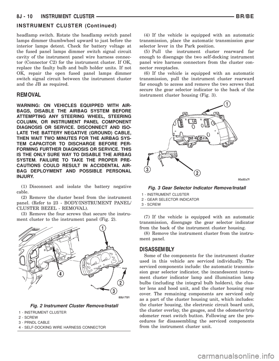
(3) Remove the four screws that secure the instru-
ment cluster to the instrument panel (Fig. 2).(4) If the vehicle is equipped with an automatic
transmission, place the automatic transmission gear
selector lever in the Park position.
(5) Pull the instrument cluster rearward far
enough to disengage the two self-docking instrument
panel wire harness connectors from the cluster con-
nector receptacles.
(6) If the vehicle is equipped with an automatic
transmission, pull the instrument cluster rearward
far enough to access and remove the two screws that
secure the gear selector indicator to the back of the
instrument cluster housing (Fig. 3).
(7) If the vehicle is equipped with an automatic
transmission, disengage the gear selector indicator
from the back of the instrument cluster housing.
(8) Remove the instrument cluster from the instru-
ment panel.
DISASSEMBLY
Some of the components for the instrument cluster
used in this vehicle are serviced individually. The
serviced components include: the automatic transmis-
sion gear selector indicator, the incandescent instru-
ment cluster indicator lamp and illumination lamp
bulbs (including the integral bulb holders), the clus-
ter lens and hood unit, and the cluster housing rear
cover. The remaining components are serviced only
as a part of the cluster housing unit, which includes:
the cluster housing, the electronic circuit board unit,
the cluster overlay, the gauges, and the odometer/trip
odometer reset switch button. Following are the pro-
cedures for disassembling the serviced components
from the instrument cluster unit.
Fig. 2 Instrument Cluster Remove/Install
1 - INSTRUMENT CLUSTER
2 - SCREW
3 - PRNDL CABLE
4 - SELF-DOCKING WIRE HARNESS CONNECTOR
Fig. 3 Gear Selector Indicator Remove/Install
1 - INSTRUMENT CLUSTER
2 - GEAR SELECTOR INDICATOR
3 - SCREW
8J - 10 INSTRUMENT CLUSTERBR/BE
INSTRUMENT CLUSTER (Continued)
Page 492 of 2255

STRUMENT PANEL/STEERING COLUMN OPEN-
ING COVER - INSTALLATION).
(8) Reconnect the battery negative cable.
CLUSTER BULB
This procedure applies to each of the incandescent
cluster illumination lamp or indicator lamp bulb and
bulb holder units. However, the illumination lamps
and the indicator lamps use different bulb and bulb
holder unit sizes. They must never be interchanged.
CAUTION: Be certain that any bulb and bulb holder
unit removed from the cluster electronic circuit
board is reinstalled in the correct position. Always
use the correct bulb size and type for replacement.
An incorrect bulb size or type may overheat and
cause damage to the instrument cluster, the elec-
tronic circuit board and/or the gauges.
(1) Insert the bulb and bulb holder unit straight
into the correct bulb mounting hole in the cluster
electronic circuit board (Fig. 5).
(2) With the bulb holder fully seated against the
cluster electronic circuit board, turn the bulb holder
clockwise about sixty degrees to lock it into place.
(3) Reinstall the instrument cluster onto the
instrument panel. (Refer to 8 - ELECTRICAL/IN-
STRUMENT CLUSTER - INSTALLATION).
(4) Reconnect the battery negative cable.
CLUSTER LENS AND HOOD
CAUTION: Do not touch the face of the gauge over-
lay or the back of the cluster lens with your finger.
It will leave a permanent finger print.
(1) Align the cluster lens and hood unit with the
cluster housing. Be certain that the odometer/trip
odometer switch button is installed through the
clearance hole in the lens (Fig. 6).
(2) Install and tighten the seven screws that
secure the lens and hood unit to the cluster housing.
Tighten the screws to 2.2 N´m (20 in. lbs.).
(3) Reinstall the instrument cluster onto the
instrument panel. (Refer to 8 - ELECTRICAL/IN-
STRUMENT CLUSTER - INSTALLATION).
(4) Reconnect the battery negative cable.
CLUSTER HOUSING REAR COVER
(1) Position the rear cover onto the back of the
cluster housing (Fig. 7).
(2) Install and tighten the six screws that secure
the rear cover to the back of the cluster housing.
Tighten the screws to 2.2 N´m (20 in. lbs.).
(3) Reinstall the instrument cluster onto the
instrument panel. (Refer to 8 - ELECTRICAL/IN-
STRUMENT CLUSTER - INSTALLATION).(4) Reconnect the battery negative cable.
CLUSTER HOUSING
(1) Assemble the rear cover onto the cluster hous-
ing. Refer to CLUSTER HOUSING REAR COVER .
(2) Assemble the lens and hood unit onto the clus-
ter housing. Refer to CLUSTER LENS AND HOOD .
(3) Reinstall the instrument cluster onto the
instrument panel. (Refer to 8 - ELECTRICAL/IN-
STRUMENT CLUSTER - INSTALLATION).
(4) Reconnect the battery negative cable.
INSTALLATION
WARNING: ON VEHICLES EQUIPPED WITH AIR-
BAGS, DISABLE THE AIRBAG SYSTEM BEFORE
ATTEMPTING ANY STEERING WHEEL, STEERING
COLUMN, OR INSTRUMENT PANEL COMPONENT
DIAGNOSIS OR SERVICE. DISCONNECT AND ISO-
LATE THE BATTERY NEGATIVE (GROUND) CABLE,
THEN WAIT TWO MINUTES FOR THE AIRBAG SYS-
TEM CAPACITOR TO DISCHARGE BEFORE PER-
FORMING FURTHER DIAGNOSIS OR SERVICE. THIS
IS THE ONLY SURE WAY TO DISABLE THE AIRBAG
SYSTEM. FAILURE TO TAKE THE PROPER PRE-
CAUTIONS COULD RESULT IN ACCIDENTAL AIR-
BAG DEPLOYMENT AND POSSIBLE PERSONAL
INJURY.
(1) Position the instrument cluster to the instru-
ment panel.
(2) If the vehicle is equipped with an automatic
transmission, position the gear selector indicator onto
the back of the cluster housing (Fig. 3).
(3) If the vehicle is equipped with an automatic
transmission, install and tighten the two screws that
secure the gear selector indicator mechanism to the
back of the cluster housing. Tighten the screws to 2.2
N´m (20 in. lbs.).
(4) Align the instrument cluster with the cluster
opening in the instrument panel and push the cluster
firmly and evenly into place. The instrument panel
wire harness has two self-docking connectors that
will be automatically aligned with, and connected to
the instrument cluster connector receptacles when
the cluster is properly installed in the instrument
panel.
(5) Install and tighten the four screws that secure
the instrument cluster to the instrument panel (Fig.
2). Tighten the screws to 2.2 N´m (20 in. lbs.).
(6) Reinstall the cluster bezel onto the instrument
panel. (Refer to 23 - BODY/INSTRUMENT PANEL/
CLUSTER BEZEL - INSTALLATION).
(7) If the vehicle is equipped with an automatic
transmission, confirm proper operation of the gear
selector indicator. Calibrate the indicator, if required.
BR/BEINSTRUMENT CLUSTER 8J - 13
INSTRUMENT CLUSTER (Continued)