2002 DODGE RAM automatic transmission
[x] Cancel search: automatic transmissionPage 1331 of 2255
(29) Inspect transmission torque convertor housing
(automatic transmission) or clutch housing (manual
transmission) for damage to timing ring on drive
plate/flywheel.
(30) Verify that battery cable and solenoid feed
wire connections to the starter solenoid are tight and
clean. Inspect for chaffed wires or wires rubbing up
against other components.
VISUAL INSPECTIONÐ8.0L ENGINE
A visual inspection for loose, disconnected or incor-
rectly routed wires and hoses should be made. This
should be done before attempting to diagnose or ser-
vice the fuel injection system. A visual check will
help spot these faults and save unnecessary test and
diagnostic time. A thorough visual inspection will
include the following checks:
(1) Verify that the three 32±way electrical connec-
tors are fully inserted into the connector of the pow-
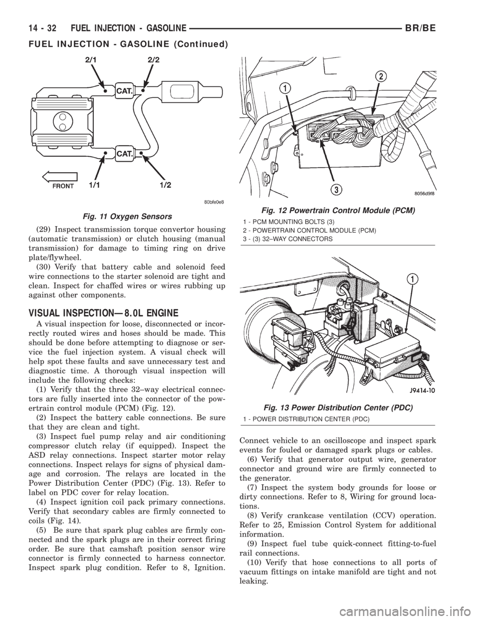
ertrain control module (PCM) (Fig. 12).
(2) Inspect the battery cable connections. Be sure
that they are clean and tight.
(3) Inspect fuel pump relay and air conditioning
compressor clutch relay (if equipped). Inspect the
ASD relay connections. Inspect starter motor relay
connections. Inspect relays for signs of physical dam-
age and corrosion. The relays are located in the
Power Distribution Center (PDC) (Fig. 13). Refer to
label on PDC cover for relay location.
(4) Inspect ignition coil pack primary connections.
Verify that secondary cables are firmly connected to
coils (Fig. 14).
(5) Be sure that spark plug cables are firmly con-
nected and the spark plugs are in their correct firing
order. Be sure that camshaft position sensor wire
connector is firmly connected to harness connector.
Inspect spark plug condition. Refer to 8, Ignition.Connect vehicle to an oscilloscope and inspect spark
events for fouled or damaged spark plugs or cables.
(6) Verify that generator output wire, generator
connector and ground wire are firmly connected to
the generator.
(7) Inspect the system body grounds for loose or
dirty connections. Refer to 8, Wiring for ground loca-
tions.
(8) Verify crankcase ventilation (CCV) operation.
Refer to 25, Emission Control System for additional
information.
(9) Inspect fuel tube quick-connect fitting-to-fuel
rail connections.
(10) Verify that hose connections to all ports of
vacuum fittings on intake manifold are tight and not
leaking.
Fig. 11 Oxygen SensorsFig. 12 Powertrain Control Module (PCM)
1 - PCM MOUNTING BOLTS (3)
2 - POWERTRAIN CONTROL MODULE (PCM)
3 - (3) 32±WAY CONNECTORS
Fig. 13 Power Distribution Center (PDC)
1 - POWER DISTRIBUTION CENTER (PDC)
14 - 32 FUEL INJECTION - GASOLINEBR/BE
FUEL INJECTION - GASOLINE (Continued)
Page 1333 of 2255
(20) Raise and support the vehicle.
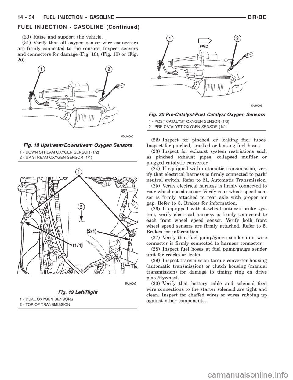
(21) Verify that all oxygen sensor wire connectors
are firmly connected to the sensors. Inspect sensors
and connectors for damage (Fig. 18), (Fig. 19) or (Fig.
20).
(22) Inspect for pinched or leaking fuel tubes.
Inspect for pinched, cracked or leaking fuel hoses.
(23) Inspect for exhaust system restrictions such
as pinched exhaust pipes, collapsed muffler or
plugged catalytic convertor.
(24) If equipped with automatic transmission, ver-
ify that electrical harness is firmly connected to park/
neutral switch. Refer to 21, Automatic Transmission.
(25) Verify electrical harness is firmly connected to
rear wheel speed sensor. Verify rear wheel speed sen-
sor is firmly attached to rear axle with proper air
gap. Refer to 5, Brakes for information.
(26) If equipped with 4±wheel antilock brake sys-
tem, verify electrical harness is firmly connected to
each front wheel speed sensor. Verify both front
wheel speed sensors are firmly attached. Refer to 5,
Brakes for information.
(27) Verify that fuel pump/gauge sender unit wire
connector is firmly connected to harness connector.
(28) Inspect fuel hoses at fuel pump/gauge sender
unit for cracks or leaks.
(29) Inspect transmission torque convertor housing
(automatic transmission) or clutch housing (manual
transmission) for damage to timing ring on drive
plate/flywheel.
(30) Verify that battery cable and solenoid feed
wire connections to the starter solenoid are tight and
clean. Inspect for chaffed wires or wires rubbing up
against other components.
Fig. 18 Upstream/Downstream Oxygen Sensors
1 - DOWN STREAM OXYGEN SENSOR (1/2)
2 - UP STREAM OXYGEN SENSOR (1/1)
Fig. 19 Left/Right
1 - DUAL OXYGEN SENSORS
2 - TOP OF TRANSMISSION
Fig. 20 Pre-Catalyst/Post Catalyst Oxygen Sensors
1 - POST CATALYST OXYGEN SENSOR (1/3)
2 - PRE-CATALYST OXYGEN SENSOR (1/2)
14 - 34 FUEL INJECTION - GASOLINEBR/BE
FUEL INJECTION - GASOLINE (Continued)
Page 1390 of 2255
FUEL INJECTION - DIESEL
TABLE OF CONTENTS
page page
FUEL INJECTION - DIESEL
DESCRIPTION - DIESEL FUEL INJECTION
SYSTEM............................91
DIAGNOSIS AND TESTING - BOOST
PRESSURE..........................93
SPECIFICATIONS
TORQUE - DIESEL ENGINE.............94
ACCELERATOR PEDAL POSITION SENSOR
DESCRIPTION.........................95
OPERATION...........................95
REMOVAL.............................95
INSTALLATION.........................97
FUEL INJECTOR
DESCRIPTION.........................97
OPERATION...........................98
DIAGNOSIS AND TESTINGÐFUEL INJECTOR
TEST...............................99
REMOVAL............................101
INSTALLATION........................102
FUEL INJECTION PUMP RELAY
DESCRIPTION........................103
OPERATION..........................103
FUEL TEMPERATURE SENSOR
DESCRIPTION........................104
OPERATION..........................104
INTAKE AIR HEATER
DESCRIPTION........................104OPERATION..........................104
REMOVAL............................104
INSTALLATION........................105
INTAKE AIR HEATER RELAY
DESCRIPTION........................105
OPERATION..........................105
REMOVAL............................106
INSTALLATION........................106
INTAKE AIR TEMPERATURE SENSOR
DESCRIPTION - DIESEL.................106
OPERATION - DIESEL..................106
REMOVAL - DIESEL....................107
INSTALLATION - DIESEL................107
MAP SENSOR
DESCRIPTION - DIESEL.................108
OPERATION - DIESEL..................108
REMOVAL - DIESEL....................108
INSTALLATION........................108
PTO SWITCH
DESCRIPTION
OPERATION........................108
THROTTLE CONTROL CABLE
REMOVAL............................109
INSTALLATION........................110
FUEL INJECTION - DIESEL
DESCRIPTION - DIESEL FUEL INJECTION
SYSTEM
The Engine Control Module (ECM) and Fuel Injec-
tion Pump Control Module (FPCM) are used prima-
rily for fuel system control. The ECM is a separate
replaceable component, while the FPCM is internal
to the fuel injection pump and is a non-serviceable
part. The ECM and FPCM are interconnected (wired
together) for fuel injection control.The Powertrain Control Module (PCM) is used to
regulate or control the A/C, charging and speed con-
trol systems. It is also used to partially control cer-
tain electronic automatic transmission components.
The PCM also has control over certain instrument
panel components.
Refer to either Powertrain Control Module (PCM)
or Engine Control Module (ECM) for additional infor-
mation. Refer to (Fig. 1) for a partial list of fuel sys-
tem components.
BR/BEFUEL INJECTION - DIESEL 14 - 91
Page 1396 of 2255
(1) Disconnect both negative battery cables at both
batteries.
(2) Remove cable cover (Fig. 6). Cable cover is
attached with 2 Phillips screws, 2 plastic retention
clips and 2 push tabs (Fig. 6). Remove 2 Phillips
screws and carefully pry out 2 retention clips. After
clip removal, push rearward on front tab, and
upward on lower tab for cover removal.
(3) Using finger pressure only, disconnect end of
speed control servo cable from throttle lever pin by
pulling forward on connector while holding lever
rearward (Fig. 7).DO NOT try to pull connector
off perpendicular to lever pin. Connector will
be broken.
(4) Using two small screwdrivers, pry throttle
cable connector socket from throttle lever ball (Fig.
7).Be very careful not to bend throttle lever
arm.
(5) Disconnect transmission control cable at lever
arm (if equipped). Refer to 21, Transmission.
(6) Squeeze pinch tabs on speed control cable (Fig.
7) and pull cable rearward to remove from cable
mounting bracket.
(7) Squeeze pinch tabs on throttle cable (Fig. 7)
and pull cable rearward to remove from cable mount-
ing bracket.
(8) If equipped with an automatic transmission,
refer to 21, Transmission for transmission control
cable removal procedures.
(9) Disconnect wiring harness clip (Fig. 8) at bot-
tom of bracket.
(10) Remove 6 mounting bolts (Fig. 8) and par-
tially remove APPS assembly from engine. After
assembly is partially removed, disconnect electrical
connector from bottom of sensor by pushing on con-
nector tab (Fig. 9).
(11) Remove APPS assembly from engine.
INSTALLATION
The APPS is serviced (replaced) as one assembly
including the lever, brackets and sensor. The APPS is
calibrated to its mounting bracket. The APPS assem-
bly is located at left-front of engine below plastic
cable/lever/linkage cover (Fig. 6) .
(1) Snap electrical connector into bottom of sensor.
(2) Position APPS assembly to engine and install 6
bolts. Tighten bolts to 12 N´m (105 in. lbs.) torque.
(3) Connect wiring harness clip (Fig. 8) at bottom
of bracket.
(4) If equipped with an automatic transmission,
refer to Group 21, Transmission for transmission con-
trol cable installation procedures.
(5) Install speed control cable into mounting
bracket. Be sure pinch tabs (Fig. 7) have secured
cable.(6) Install throttle cable into mounting bracket. Be
sure pinch tabs (Fig. 7) have secured cable.
(7) Connect throttle cable at lever (snaps on).
(8) Connect speed control cable to lever by pushing
cable connector rearward onto lever pin while hold-
ing lever forward.
(9) Install cable cover.
(10) Connect both negative battery cables to both
batteries.
(11)ECM Calibration:Turn key to ON position.
Without starting engine, slowly press throttle pedal
to floor and then slowly release. This step must be
done (one time) to ensure accelerator pedal position
sensor calibration has been learned by ECM. If not
done, possible DTC's may be set.
(12) Use DRB scan tool to erase any DTC's from
ECM/PCM.
FUEL INJECTOR
DESCRIPTION
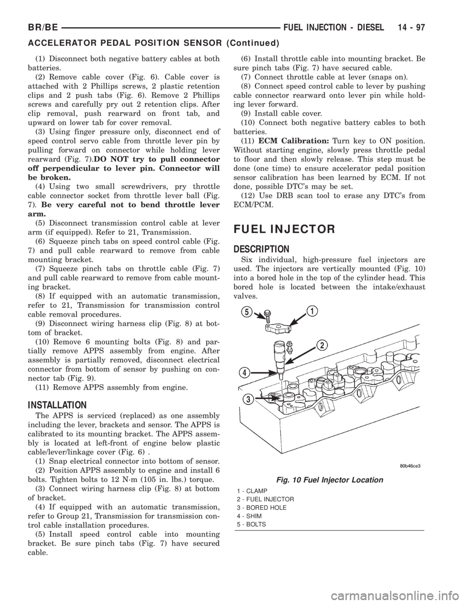
Six individual, high-pressure fuel injectors are
used. The injectors are vertically mounted (Fig. 10)
into a bored hole in the top of the cylinder head. This
bored hole is located between the intake/exhaust
valves.
Fig. 10 Fuel Injector Location
1 - CLAMP
2 - FUEL INJECTOR
3 - BORED HOLE
4 - SHIM
5 - BOLTS
BR/BEFUEL INJECTION - DIESEL 14 - 97
ACCELERATOR PEDAL POSITION SENSOR (Continued)
Page 1418 of 2255
(3) Remove the shipping lock pin if necessary.
(4) Install the column through the floor pan.
(5) Position the column bracket breakaway cap-
sules on the mounting studs. Install, butloose
assemblethe two upper bracket nuts.
(6) With the front wheels in the straight-ahead
position. Align steering column shaft to the coupler.
Install anewpinch bolt and tighten to 49 N´m (36
ft. lbs.).
(7) Clip the wiring harness on the steering column.
Connect the multi- function switch wiring and
tighten with 7mm socket.
(8) Install the upper fixed shroud.
(9) Be sure both breakaway capsules are fully
seated in the slots in the column support bracket.
Pull the column rearward then tighten upper bracket
nuts to 12 N´m (105 in. lbs.).
(10) Tighten the toe plate to floor pan attaching
nuts to 22.5 N´m (200 in. lbs.).
(11) Install the wiring connections to the column.
Install the lower fixed shroud.
(12) Column shift vehicles, install the PRNDL
driver cable. Place shifter in Park position. If indica-tor needs adjusting, turn thumb screw on cable
retainer to adjust cable.
(13) Install the lock housing shrouds. Install the
tilt lever (if equipped).
(14) Install the knee blocker and steering column
opening cover, (Refer to 23 - BODY/INSTRUMENT
PANEL/STEERING COLUMN OPENING COVER -
INSTALLATION).
(15) Install steering wheel and tighten nut to 61
N´m (45 ft. lbs.), (Refer to 19 - STEERING/COL-
UMN/STEERING WHEEL - INSTALLATION).
(16) Install the airbag, (Refer to 8 - ELECTRICAL/
RESTRAINTS/DRIVER AIRBAG - INSTALLATION).
(17) Column shift vehicles, connect the shift link
rod to the transmission shift lever. Use multi-purpose
lubricant, or an equivalent product, to aid the instal-
lation.
(18) Install the battery ground (negative) cable.
(19) Verify operation of the automatic transmission
shift linkage and adjust as necessary, (Refer to 21 -
TRANSMISSION/TRANSAXLE/AUTOMATIC -
44RE/GEAR SHIFT CABLE - ADJUSTMENTS).
SPECIFICATIONS
TORQUE CHART
TORQUE SPECIFICATIONS
DESCRIPTION N´m Ft. Lbs. In. Lbs.
Steering Wheel
Nut61 45 Ð
Steering Coupler
Bolt49 36 Ð
Steering Column
Upper Bracket12 Ð 105
Steering Column
Toe Plate23 Ð 200
KEY-IN IGNITION SWITCH
DESCRIPTION
The key-in ignition switch is integral to the igni-
tion switch, which is mounted on the left side of the
steering column. It closes a path to ground for the
Central Timer Module (CTM) when the ignition key
is inserted in the ignition lock cylinder and the
driver door ajar switch is closed (driver door is open).
The key-in ignition switch opens the ground path
when the key is removed from the ignition lock cyl-
inder. The ground path is also opened when the
driver door ajar switch is open (driver door is closed).The key-in ignition switch cannot be repaired and,
if faulty or damaged, the entire ignition switch must
be replaced, (Refer to 19 - STEERING/COLUMN/IG-
NITION SWITCH - REMOVAL).
DIAGNOSIS AND TESTING - IGNITION SWITCH
AND KEY LOCK CYLINDER
ELECTRICAL DIAGNOSIS
For ignition switch electrical schematics, refer to
Ignition Switch in the appropriate section of Electri-
cal Wiring Diagrams.
BR/BECOLUMN 19 - 9
COLUMN (Continued)
Page 1419 of 2255
MECHANICAL DIAGNOSIS (KEY DIFFICULT TO
ROTATE)
Vehicles equipped with an automatic trans-
mission and a floor mounted shifter:a cable is
used to connect the interlock device in the steering
column assembly, to the transmission floor shift
lever. This interlock device is used to lock the trans-
mission shifter in the PARK position when the key
lock cylinder is rotated to the LOCKED or ACCES-
SORY position. The interlock device within the steer-
ing column is not serviceable. If repair is necessary,
the steering column assembly must be replaced.
(Refer to 19 - STEERING/COLUMN - REMOVAL).
If the ignition key is difficult to rotate to or from
the LOCK or ACCESSORY position, it may not be
the fault of the key cylinder or the steering column
components. The brake transmission shift interlock
cable may be out of adjustment. Refer to Brake
Transmission Shift Interlock Cable Adjustment in
Transmissions for adjustment procedures.
Vehicles equipped with an automatic trans-
mission and a steering column mounted shifter:
an interlock device is located within the steering col-
umn. This interlock device is used to lock the trans-
mission shifter in the PARK position when the key
lock cylinder is in the LOCKED or ACCESSORY
position. If it is difficult to rotate the key to or from
the LOCK or ACCESSORY position, the interlock
device within the steering column may be defective.
This device is not serviceable. If repair is necessary,
the steering column assembly must be replaced.
(Refer to 19 - STEERING/COLUMN - REMOVAL).
Vehicles equipped with a manual transmis-
sion and a floor mounted shifter:on certain mod-
els, a lever is located on the steering column behind
the ignition key lock cylinder. The lever must be
manually operated to allow rotation of the ignition
key lock cylinder to the LOCK or ACCESSORY posi-
tion. If it is difficult to rotate the key to the LOCK or
ACCESSORY position, the lever mechanism may be
defective. This mechanism is not serviceable. If
repair is necessary, the steering column assembly
must be replaced. (Refer to 19 - STEERING/COL-
UMN - REMOVAL).
On other models, the ignition key cylinder must be
depressed to allow it to be rotated into the LOCK or
ACCESSORY position. If it is difficult to rotate the
key to the LOCK or ACCESSORY position, the lock
mechanism within the steering column may be defec-
tive. This mechanism is not serviceable. If repair is
necessary, the steering column assembly must be
replaced. (Refer to 19 - STEERING/COLUMN -
REMOVAL).
LOCK CYLINDER
REMOVAL
The ignition key must be in the key cylinder for
cylinder removal.
(1) Disconnect negative cable from battery.
(2) If equipped with tilt column, remove tilt lever
by turning it counterclockwise.
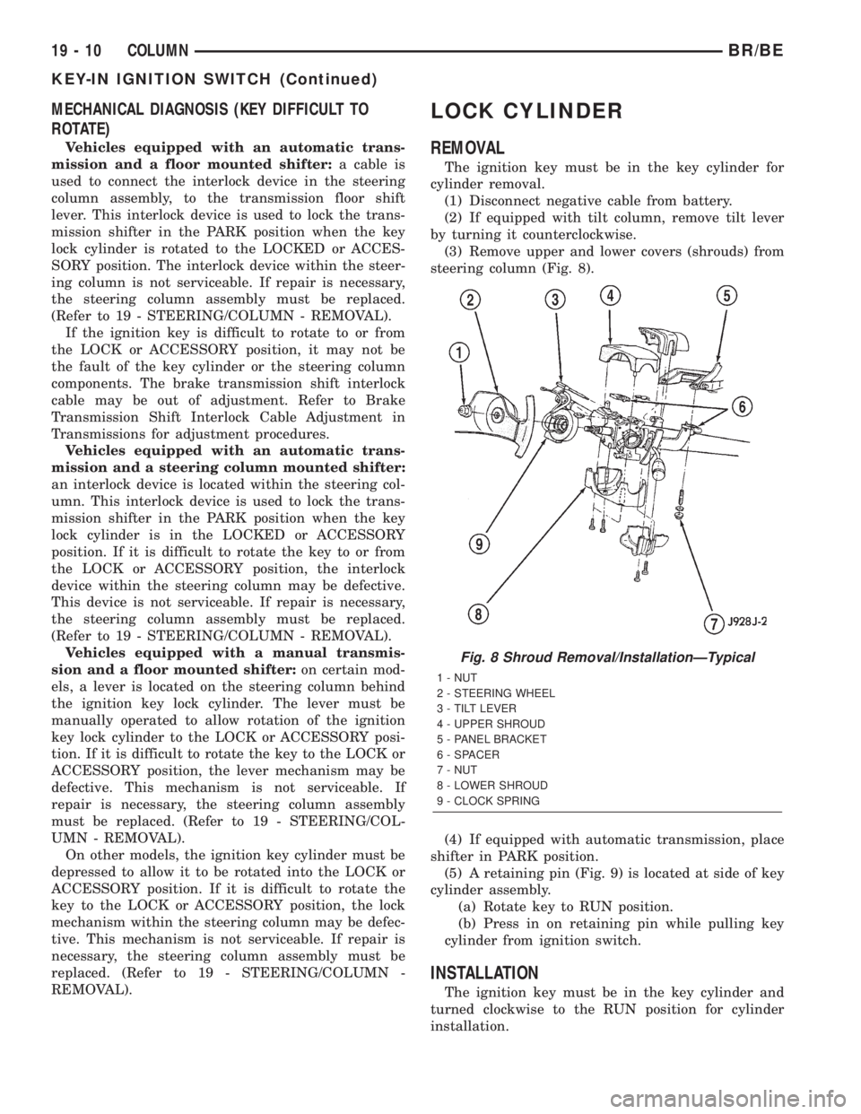
(3) Remove upper and lower covers (shrouds) from
steering column (Fig. 8).
(4) If equipped with automatic transmission, place
shifter in PARK position.
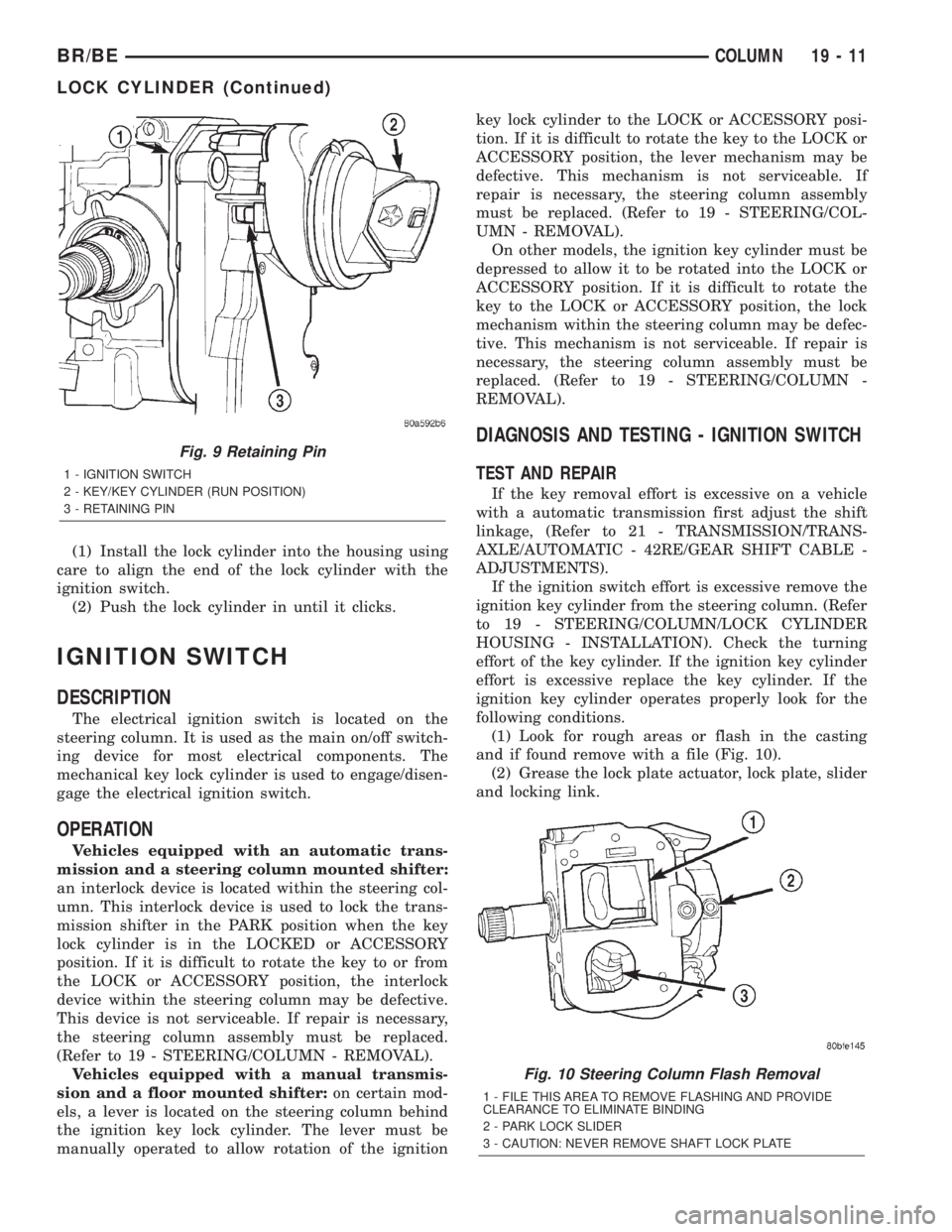
(5) A retaining pin (Fig. 9) is located at side of key
cylinder assembly.
(a) Rotate key to RUN position.
(b) Press in on retaining pin while pulling key
cylinder from ignition switch.
INSTALLATION
The ignition key must be in the key cylinder and
turned clockwise to the RUN position for cylinder
installation.
Fig. 8 Shroud Removal/InstallationÐTypical
1 - NUT
2 - STEERING WHEEL
3 - TILT LEVER
4 - UPPER SHROUD
5 - PANEL BRACKET
6 - SPACER
7 - NUT
8 - LOWER SHROUD
9 - CLOCK SPRING
19 - 10 COLUMNBR/BE
KEY-IN IGNITION SWITCH (Continued)
Page 1420 of 2255
(1) Install the lock cylinder into the housing using
care to align the end of the lock cylinder with the
ignition switch.
(2) Push the lock cylinder in until it clicks.
IGNITION SWITCH
DESCRIPTION
The electrical ignition switch is located on the
steering column. It is used as the main on/off switch-
ing device for most electrical components. The
mechanical key lock cylinder is used to engage/disen-
gage the electrical ignition switch.
OPERATION
Vehicles equipped with an automatic trans-
mission and a steering column mounted shifter:
an interlock device is located within the steering col-
umn. This interlock device is used to lock the trans-
mission shifter in the PARK position when the key
lock cylinder is in the LOCKED or ACCESSORY
position. If it is difficult to rotate the key to or from
the LOCK or ACCESSORY position, the interlock
device within the steering column may be defective.
This device is not serviceable. If repair is necessary,
the steering column assembly must be replaced.
(Refer to 19 - STEERING/COLUMN - REMOVAL).
Vehicles equipped with a manual transmis-
sion and a floor mounted shifter:on certain mod-
els, a lever is located on the steering column behind
the ignition key lock cylinder. The lever must be
manually operated to allow rotation of the ignitionkey lock cylinder to the LOCK or ACCESSORY posi-
tion. If it is difficult to rotate the key to the LOCK or
ACCESSORY position, the lever mechanism may be
defective. This mechanism is not serviceable. If
repair is necessary, the steering column assembly
must be replaced. (Refer to 19 - STEERING/COL-
UMN - REMOVAL).
On other models, the ignition key cylinder must be
depressed to allow it to be rotated into the LOCK or
ACCESSORY position. If it is difficult to rotate the
key to the LOCK or ACCESSORY position, the lock
mechanism within the steering column may be defec-
tive. This mechanism is not serviceable. If repair is
necessary, the steering column assembly must be
replaced. (Refer to 19 - STEERING/COLUMN -
REMOVAL).
DIAGNOSIS AND TESTING - IGNITION SWITCH
TEST AND REPAIR
If the key removal effort is excessive on a vehicle
with a automatic transmission first adjust the shift
linkage, (Refer to 21 - TRANSMISSION/TRANS-
AXLE/AUTOMATIC - 42RE/GEAR SHIFT CABLE -
ADJUSTMENTS).
If the ignition switch effort is excessive remove the
ignition key cylinder from the steering column. (Refer
to 19 - STEERING/COLUMN/LOCK CYLINDER
HOUSING - INSTALLATION). Check the turning
effort of the key cylinder. If the ignition key cylinder
effort is excessive replace the key cylinder. If the
ignition key cylinder operates properly look for the
following conditions.
(1) Look for rough areas or flash in the casting
and if found remove with a file (Fig. 10).
(2) Grease the lock plate actuator, lock plate, slider
and locking link.
Fig. 9 Retaining Pin
1 - IGNITION SWITCH
2 - KEY/KEY CYLINDER (RUN POSITION)
3 - RETAINING PIN
Fig. 10 Steering Column Flash Removal
1 - FILE THIS AREA TO REMOVE FLASHING AND PROVIDE
CLEARANCE TO ELIMINATE BINDING
2 - PARK LOCK SLIDER
3 - CAUTION: NEVER REMOVE SHAFT LOCK PLATE
BR/BECOLUMN 19 - 11
LOCK CYLINDER (Continued)
Page 1421 of 2255
REMOVAL
(1) Remove the key lock cylinder.
(2) Remove the three ignition mounting screws
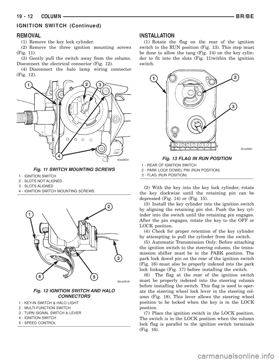
(Fig. 11).
(3) Gently pull the switch away from the column.
Disconnect the electrical connector (Fig. 12).
(4) Disconnect the halo lamp wiring connector
(Fig. 12).
INSTALLATION
(1) Rotate the flag on the rear of the ignition
switch to the RUN position (Fig. 13). This step must
be done to allow the tang (Fig. 14) on the key cylin-
der to fit into the slots (Fig. 11)within the ignition
switch.
(2) With the key into the key lock cylinder, rotate
the key clockwise until the retaining pin can be
depressed (Fig. 14) or (Fig. 15).
(3) Install the key cylinder into the ignition switch
by aligning the retaining pin slot. Push the key cyl-
inder into the switch until the retaining pin engages.
After the pin engages, rotate the key to the OFF or
LOCK position.
(4) Check for proper retention of the key cylinder
by attempting to pull the cylinder from the switch.
(5) Automatic Transmission Only: Before attaching
the ignition switch to the steering column, the trans-
mission shifter must be in the PARK position. The
park lock dowel pin on the rear of the ignition switch
(Fig. 16) must also be properly indexed into the park
lock linkage (Fig. 17) before installing the switch.
(6) The flag at the rear of the ignition switch
must be properly indexed into the steering column
before installing the switch. This flag is used to oper-
ate the steering wheel lock lever in the steering col-
umn (Fig. 18). This lever allows the steering wheel
position to be locked when the key is in the LOCK
position.
(7) Place the ignition switch in the LOCK position.
The switch is in the LOCK position when the column
lock flag is parallel to the ignition switch terminals
(Fig. 16).
Fig. 11 SWITCH MOUNTING SCREWS
1 - IGNITION SWITCH
2 - SLOTS NOT ALIGNED
3 - SLOTS ALIGNED
4 - IGNITION SWITCH MOUNTING SCREWS
Fig. 12 IGNITION SWITCH AND HALO
CONNECTORS
1 - KEY-IN SWITCH & HALO LIGHT
2 - MULTI-FUNCTION SWITCH
3 - TURN SIGNAL SWITCH & LEVER
4 - IGNITION SWITCH
5 - SPEED CONTROL
Fig. 13 FLAG IN RUN POSITION
1 - REAR OF IGNITION SWITCH
2 - PARK LOCK DOWEL PIN (RUN POSITION)
3 - FLAG (RUN POSITION)
19 - 12 COLUMNBR/BE
IGNITION SWITCH (Continued)