2002 DODGE RAM automatic transmission
[x] Cancel search: automatic transmissionPage 1422 of 2255

(8) Automatic Transmissions Only: Apply a light
coating of grease to the park lock dowel pin and park
lock slider linkage. Before installing the switch, push
the park lock slider linkage (Fig. 17)forward until it
bottoms. Do a final positioning by pulling it rear-
wards about one-quarter inch.
(9) Apply a light coating of grease to both the col-
umn lock flag and shaft at the end of the flag.
(10) Place the ignition switch into the openings on
the steering column(a) Automatic Transmissions Only: Be sure the
park lock dowel pin on the rear of the ignition
switch enters the slot in the park lock slider link-
age (Fig. 17).
(b) Be sure the flag on the rear of the switch is
positioned above the steering wheel lock lever (Fig.
18).
(c) Align the dowel pins on the rear of the switch
into the holes on the side of the steering column.
(d) Install the three ignition mounting screws.
Tighten the screws to 2 N´m (17 in. lbs.).
Fig. 14 KEY CYLINDER --- REAR VIEW
1 - IGNITION KEY LOCK CYLINDER
2 - PUSH PIN
3 - RETAINING PIN SLOT
4 - RETAINING PIN
5 - DRIVER
Fig. 15 INSTALLING KEY CYLINDER INTO SWITCH
1 - IGNITION SWITCH
2 - DRIVER
3 - IGNITION KEY LOCK CYLINDER
4 - RETAINING PIN
5 - RETAINING PIN SLOT
Fig. 16 IGNITION SWITCH VIEW FROM COLUMN
1 - REAR OF IGNITION SWITCH
2 - PARK LOCK DOWEL PIN (LOCK POSITION)
3 - FLAG (LOCK POSITION)
Fig. 17 PARK LOCK LINKAGE -- AUTOMATIC
TRANSMISSION -- TYPICAL
1 - DOWEL LOCATING HOLES (2)
2 - PARK LOCK SLIDER LINKAGE
3 - IGNITION SWITCH MOUNTING PAD
4 - STEERING COLUMN
5 - SLOT
BR/BECOLUMN 19 - 13
IGNITION SWITCH (Continued)
Page 1423 of 2255
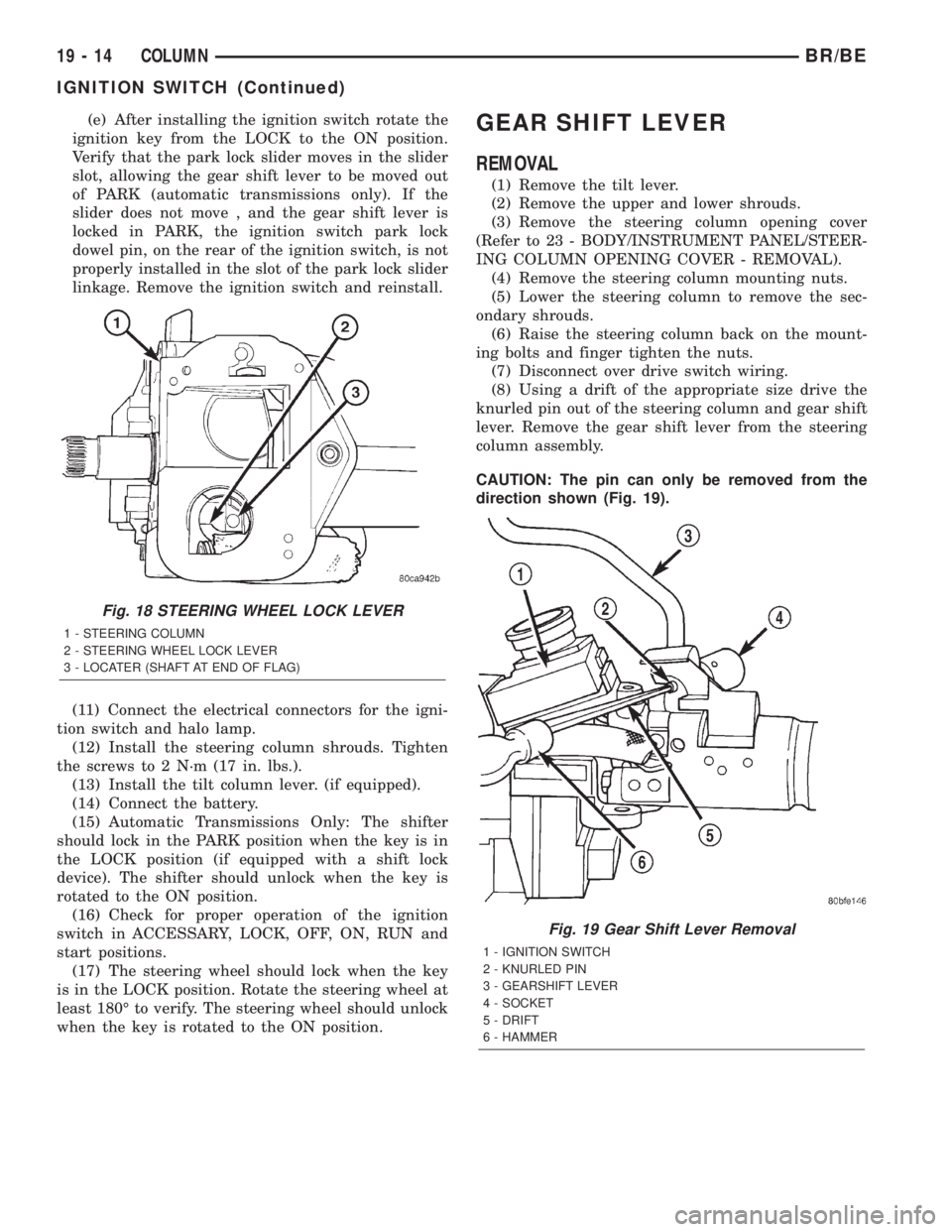
(e) After installing the ignition switch rotate the
ignition key from the LOCK to the ON position.
Verify that the park lock slider moves in the slider
slot, allowing the gear shift lever to be moved out
of PARK (automatic transmissions only). If the
slider does not move , and the gear shift lever is
locked in PARK, the ignition switch park lock
dowel pin, on the rear of the ignition switch, is not
properly installed in the slot of the park lock slider
linkage. Remove the ignition switch and reinstall.
(11) Connect the electrical connectors for the igni-
tion switch and halo lamp.
(12) Install the steering column shrouds. Tighten
the screws to 2 N´m (17 in. lbs.).
(13) Install the tilt column lever. (if equipped).
(14) Connect the battery.
(15) Automatic Transmissions Only: The shifter
should lock in the PARK position when the key is in
the LOCK position (if equipped with a shift lock
device). The shifter should unlock when the key is
rotated to the ON position.
(16) Check for proper operation of the ignition
switch in ACCESSARY, LOCK, OFF, ON, RUN and
start positions.
(17) The steering wheel should lock when the key
is in the LOCK position. Rotate the steering wheel at
least 180É to verify. The steering wheel should unlock
when the key is rotated to the ON position.GEAR SHIFT LEVER
REMOVAL
(1) Remove the tilt lever.
(2) Remove the upper and lower shrouds.
(3) Remove the steering column opening cover
(Refer to 23 - BODY/INSTRUMENT PANEL/STEER-
ING COLUMN OPENING COVER - REMOVAL).
(4) Remove the steering column mounting nuts.
(5) Lower the steering column to remove the sec-
ondary shrouds.
(6) Raise the steering column back on the mount-
ing bolts and finger tighten the nuts.
(7) Disconnect over drive switch wiring.
(8) Using a drift of the appropriate size drive the
knurled pin out of the steering column and gear shift
lever. Remove the gear shift lever from the steering
column assembly.
CAUTION: The pin can only be removed from the
direction shown (Fig. 19).
Fig. 18 STEERING WHEEL LOCK LEVER
1 - STEERING COLUMN
2 - STEERING WHEEL LOCK LEVER
3 - LOCATER (SHAFT AT END OF FLAG)
Fig. 19 Gear Shift Lever Removal
1 - IGNITION SWITCH
2 - KNURLED PIN
3 - GEARSHIFT LEVER
4 - SOCKET
5 - DRIFT
6 - HAMMER
19 - 14 COLUMNBR/BE
IGNITION SWITCH (Continued)
Page 1442 of 2255
PUMP
TABLE OF CONTENTS
page page
PUMP
DESCRIPTION.........................33
OPERATION...........................33
DIAGNOSIS AND TESTING - PUMP LEAKAGE . 33
STANDARD PROCEDURE
STANDARD PROCEDURE - POWER
STEERING PUMP - INITIAL OPERATION....33
STANDARD PROCEDURE - FLUSHING
POWER STEERING SYSTEM............34
REMOVAL
REMOVAL - GASOLINE ENGINE..........35
REMOVAL - DIESEL ENGINE............36
INSTALLATION
INSTALLATION - GASOLINE ENGINE......37INSTALLATION - DIESEL ENGINE.........37
SPECIAL TOOLS
POWER STEERING PUMP..............38
PULLEY
REMOVAL.............................38
INSTALLATION.........................39
HOSES - PRESSURE
DESCRIPTION.........................39
OPERATION...........................39
HOSES - RETURN
DESCRIPTION.........................39
OPERATION...........................39
PUMP
DESCRIPTION
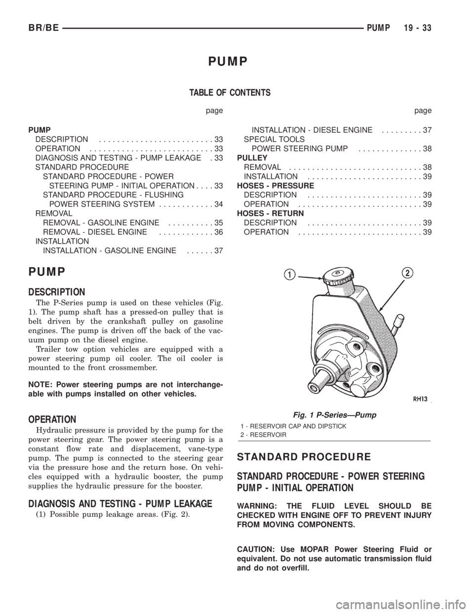
The P-Series pump is used on these vehicles (Fig.
1). The pump shaft has a pressed-on pulley that is
belt driven by the crankshaft pulley on gasoline
engines. The pump is driven off the back of the vac-
uum pump on the diesel engine.
Trailer tow option vehicles are equipped with a
power steering pump oil cooler. The oil cooler is
mounted to the front crossmember.
NOTE: Power steering pumps are not interchange-
able with pumps installed on other vehicles.
OPERATION
Hydraulic pressure is provided by the pump for the
power steering gear. The power steering pump is a
constant flow rate and displacement, vane-type
pump. The pump is connected to the steering gear
via the pressure hose and the return hose. On vehi-
cles equipped with a hydraulic booster, the pump
supplies the hydraulic pressure for the booster.
DIAGNOSIS AND TESTING - PUMP LEAKAGE
(1) Possible pump leakage areas. (Fig. 2).
STANDARD PROCEDURE
STANDARD PROCEDURE - POWER STEERING
PUMP - INITIAL OPERATION
WARNING: THE FLUID LEVEL SHOULD BE
CHECKED WITH ENGINE OFF TO PREVENT INJURY
FROM MOVING COMPONENTS.
CAUTION: Use MOPAR Power Steering Fluid or
equivalent. Do not use automatic transmission fluid
and do not overfill.
Fig. 1 P-SeriesÐPump
1 - RESERVOIR CAP AND DIPSTICK
2 - RESERVOIR
BR/BEPUMP 19 - 33
Page 1454 of 2255
TRANSMISSION AND TRANSFER CASE
TABLE OF CONTENTS
page page
MANUAL - NV4500........................1
MANUAL - NV5600.......................46
AUTOMATIC TRANSMISSION - 46RE.........87AUTOMATIC TRANSMISSION - 47RE........259
TRANSFER CASE - NV241LD..............430
TRANSFER CASE - NV241HD.............465
MANUAL - NV4500
TABLE OF CONTENTS
page page
MANUAL - NV4500
DESCRIPTION..........................1
OPERATION............................3
DIAGNOSIS AND TESTING................3
REMOVAL.............................4
DISASSEMBLY..........................5
CLEANING............................20
INSPECTION..........................20
ASSEMBLY............................21
INSTALLATION.........................37
SPECIFICATIONS.......................38
SPECIAL TOOLS.......................38ADAPTER HOUSING SEAL - NV4500
REMOVAL.............................42
INSTALLATION.........................42
EXTENSION HOUSING SEAL - NV4500
REMOVAL.............................42
INSTALLATION.........................42
SHIFT MECHANISM - NV4500
REMOVAL.............................43
INSTALLATION.........................44
SHIFT COVER - NV4500
REMOVAL.............................45
INSTALLATION.........................45
MANUAL - NV4500
DESCRIPTION
The NV4500 is a five speed constant mesh manual
transmission (Fig. 1). All gear ranges including
reverse are synchronized. Fifth gear is an overdrive
range. The transmission has a cast iron gear case
and aluminum shift cover.
Two versions are used, a standard duty for 5.9L
applications and a heavy duty for V10 and Cummins
diesel applications. Main differences are the larger
diameter input shaft, output shaft and mainshaft
fifth gear in the heavy duty model.
Tapered roller bearings support the drive gear,
mainshaft and countershaft in the gear case. Roller
bearings in the drive gear support the forward end ofthe mainshaft. The mainshaft gears are all supported
on caged type roller bearings. Drive gear thrust reac-
tion is controlled by a needle type thrust bearing.
The bearing is located at the forward end of the
mainshaft.
The transmission is a top loader style. The shift
lever is located in a shifter tower which is bolted to
the shift cover and operates the shift forks and rails
directly. The shift forks and rails are all located
within the aluminum cover which is bolted to the top
of the gear case.
SHIFT PATTERN
The shift pattern is in a modified H pattern (Fig.
2). Overdrive fifth and reverse gears are in line and
outboard of the first through fourth gear positions.
BR/BETRANSMISSION AND TRANSFER CASE 21 - 1
Page 1540 of 2255
AUTOMATIC TRANSMISSION - 46RE
TABLE OF CONTENTS
page page
AUTOMATIC TRANSMISSION - 46RE
DESCRIPTION.........................89
OPERATION...........................91
DIAGNOSIS AND TESTING
DIAGNOSIS AND TESTING - AUTOMATIC
TRANSMISSION......................96
DIAGNOSIS AND TESTING - PRELIMINARY . 97
DIAGNOSIS AND TESTING - ROAD
TESTING............................97
DIAGNOSIS AND TESTING - HYDRAULIC
PRESSURE TEST.....................98
DIAGNOSIS AND TESTING - AIR TESTING
TRANSMISSION CLUTCH AND BAND
OPERATION........................100
DIAGNOSIS AND TESTING - CONVERTER
HOUSING FLUID LEAK................101
DIAGNOSIS AND TESTING - DIAGNOSIS
CHARTS...........................102
STANDARD PROCEDURE - ALUMINUM
THREAD REPAIR.....................114
REMOVAL............................114
DISASSEMBLY........................115
CLEANING...........................122
INSPECTION.........................122
ASSEMBLY...........................122
INSTALLATION........................130
SCHEMATICS AND DIAGRAMS
HYDRAULIC SCHEMATICS.............132
SPECIFICATIONS
TRANSMISSION.....................144
SPECIAL TOOLS
RE TRANSMISSION..................146
ACCUMULATOR
DESCRIPTION........................149
OPERATION..........................150
INSPECTION.........................150
BANDS
DESCRIPTION........................150
OPERATION..........................151
ADJUSTMENTS
ADJUSTMENT - BANDS...............151
ELECTRONIC GOVERNOR
DESCRIPTION........................152
OPERATION..........................153
REMOVAL............................154
INSTALLATION........................154
EXTENSION HOUSING BUSHING
REMOVAL............................156
INSTALLATION........................156EXTENSION HOUSING SEAL
REMOVAL............................156
INSTALLATION........................156
FLUID AND FILTER
DIAGNOSIS AND TESTING
DIAGNOSIS AND TESTING - EFFECTS OF
INCORRECT FLUID LEVEL.............157
DIAGNOSIS AND TESTING - CAUSES OF
BURNT FLUID.......................157
DIAGNOSIS AND TESTING - FLUID
CONTAMINATION....................157
STANDARD PROCEDURE
STANDARD PROCEDURE - FLUID LEVEL
CHECK............................157
STANDARD PROCEDURE - FLUID AND
FILTER REPLACEMENT...............158
STANDARD PROCEDURE - TRANSMISSION
FILL...............................160
FRONT CLUTCH
DESCRIPTION........................160
OPERATION..........................160
DISASSEMBLY........................161
INSPECTION.........................162
ASSEMBLY...........................162
FRONT SERVO
DESCRIPTION........................164
OPERATION..........................164
DISASSEMBLY........................164
CLEANING...........................164
INSPECTION.........................164
ASSEMBLY...........................164
OIL PUMP
DESCRIPTION........................166
OPERATION..........................166
STANDARD PROCEDURE - OIL PUMP
VOLUME CHECK.....................166
DISASSEMBLY........................167
CLEANING...........................168
INSPECTION.........................168
ASSEMBLY...........................169
OUTPUT SHAFT FRONT BEARING
REMOVAL............................171
INSTALLATION........................171
OUTPUT SHAFT REAR BEARING
REMOVAL............................171
INSTALLATION........................172
OVERDRIVE CLUTCH
DESCRIPTION........................172
OPERATION..........................172
BR/BEAUTOMATIC TRANSMISSION - 46RE 21 - 87
Page 1541 of 2255
OVERDRIVE UNIT
REMOVAL............................173
DISASSEMBLY........................173
CLEANING...........................179
INSPECTION.........................180
ASSEMBLY...........................180
INSTALLATION........................189
OVERDRIVE SWITCH
DESCRIPTION........................190
OPERATION..........................190
DIAGNOSIS AND TESTING - OVERDRIVE
ELECTRICAL CONTROLS..............191
REMOVAL............................191
INSTALLATION........................191
OVERRUNNING CLUTCH CAM/OVERDRIVE
PISTON RETAINER
DESCRIPTION........................192
OPERATION..........................192
DISASSEMBLY........................192
CLEANING...........................192
INSPECTION.........................193
ASSEMBLY...........................193
PARK/NEUTRAL POSITION SWITCH
DIAGNOSIS AND TESTING - PARK/NEUTRAL
POSITION SWITCH...................195
REMOVAL............................195
INSTALLATION........................195
PISTONS
DESCRIPTION........................195
OPERATION..........................196
PLANETARY GEARTRAIN/OUTPUT SHAFT
DESCRIPTION........................197
OPERATION..........................197
DISASSEMBLY........................198
INSPECTION.........................199
ASSEMBLY...........................199
REAR CLUTCH
DESCRIPTION........................203
OPERATION..........................203
DISASSEMBLY........................204
CLEANING...........................204
INSPECTION.........................204
ASSEMBLY...........................205
REAR SERVO
DESCRIPTION........................207OPERATION..........................207
DISASSEMBLY........................207
CLEANING...........................207
ASSEMBLY...........................207
SHIFT MECHANISM
DESCRIPTION........................208
OPERATION..........................208
ADJUSTMENTS
ADJUSTMENT.......................208
SOLENOID
DESCRIPTION........................208
OPERATION..........................209
SPEED SENSOR
DESCRIPTION........................209
OPERATION..........................209
THROTTLE VALVE CABLE
DESCRIPTION........................209
ADJUSTMENTS - TRANSMISSION THROTTLE
VALVE CABLE.......................210
TORQUE CONVERTER
DESCRIPTION........................212
OPERATION..........................215
REMOVAL............................216
INSTALLATION........................217
TORQUE CONVERTER DRAINBACK VALVE
DESCRIPTION........................217
OPERATION..........................217
STANDARD PROCEDURE - TORQUE
CONVERTER DRAINBACK VALVE........217
TRANSMISSION TEMPERATURE SENSOR
DESCRIPTION........................218
OPERATION..........................218
VALVE BODY
DESCRIPTION........................218
OPERATION..........................223
REMOVAL............................236
DISASSEMBLY........................237
CLEANING...........................244
INSPECTION.........................244
ASSEMBLY...........................248
INSTALLATION........................256
ADJUSTMENTS - VALVE BODY...........257
21 - 88 AUTOMATIC TRANSMISSION - 46REBR/BE
Page 1542 of 2255
AUTOMATIC TRANSMISSION -
46RE
DESCRIPTION
The 46RE (Fig. 1) is a four speed fully automatic
transmissions with an electronic governor. The 46RE
is equipped with a lock-up clutch in the torque con-
verter. First through third gear ranges are provided
by the clutches, bands, overrunning clutch, and plan-
etary gear sets in the transmission. Fourth gear
range is provided by the overdrive unit that contains
an overdrive clutch, direct clutch, planetary gear set,
and overrunning clutch.The transmission contains a front, rear, and direct
clutch which function as the input driving compo-
nents. It also contains the kickdown (front) and the
low/reverse (rear) bands which, along with the over-
running clutch and overdrive clutch, serve as the
holding components. The driving and holding compo-
nents combine to select the necessary planetary gear
components, in the front, rear, or overdrive planetary
gear set, transfer the engine power from the input
shaft through to the output shaft.
The valve body is mounted to the lower side of the
transmission and contains the valves to control pres-
sure regulation, fluid flow control, and clutch/band
application. The oil pump is mounted at the front of
the transmission and is driven by the torque con-
verter hub. The pump supplies the oil pressure nec-
essary for clutch/band actuation and transmission
lubrication.
BR/BEAUTOMATIC TRANSMISSION - 46RE 21 - 89
Page 1543 of 2255
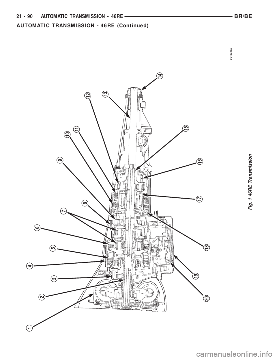
Fig. 1 46RE Transmission
21 - 90 AUTOMATIC TRANSMISSION - 46REBR/BE
AUTOMATIC TRANSMISSION - 46RE (Continued)