2002 DODGE RAM automatic transmission
[x] Cancel search: automatic transmissionPage 601 of 2255

(b) Depress the connector latch tab and pull the
connector straight away from the ACM connector
receptacle.
NOTE: Always remove and replace the ACM and its
mounting bracket as a unit. Replacement modules
include a replacement mounting bracket. Do not
transfer the ACM to another mounting bracket.
(9) Remove the four screws that secure the ACM
mounting bracket to the floor panel transmission
tunnel.
(10) Remove the ACM, the mounting bracket, and
the instrument panel center support bracket from the
floor panel transmission tunnel as a unit.
INSTALLATION
WARNING: DISABLE THE AIRBAG SYSTEM
BEFORE ATTEMPTING ANY STEERING WHEEL,
STEERING COLUMN, OR INSTRUMENT PANEL
COMPONENT DIAGNOSIS OR SERVICE. DISCON-
NECT AND ISOLATE THE BATTERY NEGATIVE
(GROUND) CABLE, THEN WAIT TWO MINUTES FOR
THE AIRBAG SYSTEM CAPACITOR TO DISCHARGE
BEFORE PERFORMING FURTHER DIAGNOSIS ORSERVICE. THIS IS THE ONLY SURE WAY TO DIS-
ABLE THE AIRBAG SYSTEM. FAILURE TO TAKE
THE PROPER PRECAUTIONS COULD RESULT IN
ACCIDENTAL AIRBAG DEPLOYMENT AND POSSI-
BLE PERSONAL INJURY.
WARNING: THE AIRBAG CONTROL MODULE CON-
TAINS THE IMPACT SENSOR, WHICH ENABLES
THE SYSTEM TO DEPLOY THE AIRBAGS. NEVER
STRIKE OR KICK THE AIRBAG CONTROL MODULE,
AS IT CAN DAMAGE THE IMPACT SENSOR OR
AFFECT ITS CALIBRATION. IF AN AIRBAG CON-
TROL MODULE IS ACCIDENTALLY DROPPED DUR-
ING SERVICE, THE MODULE MUST BE SCRAPPED
AND REPLACED WITH A NEW UNIT. FAILURE TO
OBSERVE THIS WARNING COULD RESULT IN ACCI-
DENTAL, INCOMPLETE, OR IMPROPER AIRBAG
DEPLOYMENT AND POSSIBLE OCCUPANT INJU-
RIES.
(1) Carefully position the Airbag Control Module
(ACM), the mounting bracket, and the instrument
panel center support bracket onto the floor panel
transmission tunnel as a unit (Fig. 6). When the
ACM is correctly positioned, the arrow on the ACM
label will be pointed forward in the vehicle.
(2) Install and tighten the four screws that secure
the ACM mounting bracket to the floor panel trans-
mission tunnel. Tighten the screws to 14 N´m (125
in. lbs.).
(3) With the instrument panel center support
bracket still folded down flat on the floor panel trans-
mission tunnel, reconnect the instrument panel wire
harness connector for the ACM to the ACM connector
receptacle. Be certain that the connector latch and
the red Connector Position Assurance (CPA) lock are
fully engaged.
(4) Fold the top of the instrument panel center
support bracket up over the top of the ACM and for-
ward over the studs on the lower instrument panel
structural support.
(5) Install and tighten the nuts that secure the
instrument panel center support bracket to the studs
on the lower instrument panel structural support.
Tighten the nuts to 14 N´m (125 in. lbs.).
(6) Engage the retainer on the instrument panel
wire harness take out for the ACM in the retainer
hole on the left side of the instrument panel center
support bracket.
(7) Tighten the screws that secure each side of the
instrument panel center support bracket to the ACM
mounting bracket. Tighten the screws 14 N´m (125
in. lbs.).
(8) If the vehicle is equipped with an automatic
transmission, position the ACM trim cover to the
ACM mounting bracket on the floor panel transmis-
sion tunnel (Fig. 5).
Fig. 6 Airbag Control Module Remove/Install
1 - INSTRUMENT PANEL
2 - SUPPORT BRACKET
3 - SCREW (2)
4 - FLOOR PANEL
5 - SCREW (4)
6 - MOUNTING BRACKET
7 - CONNECTOR
8 - ACM
9 - RETAINER
10 - NUT
8O - 8 RESTRAINTSBR/BE
AIRBAG CONTROL MODULE (Continued)
Page 602 of 2255
(9) If the vehicle is equipped with an automatic
transmission, install and tighten the two screws that
secure the ACM trim cover to the ACM mounting
bracket. Tighten the screws to 2.2 N´m (20 in. lbs.).
(10) If the vehicle is equipped with a manual
transmission, reinstall the center floor console onto
the floor panel transmission tunnel. (Refer to 23 -
BODY/INTERIOR/CENTER CONSOLE - INSTALLA-
TION).
(11) Do not reconnect the battery negative cable at
this time. The airbag system verification test proce-
dure should be performed following service of any
airbag system component. (Refer to 8 - ELECTRI-
CAL/RESTRAINTS - STANDARD PROCEDURE -
VERIFICATION TEST).
CHILD TETHER
REMOVAL
Standard cab models have two child tether anchors
secured near the top of the cab back panel. Club cab
and quad cab models have three child tethers
secured near the top of the cab back panel.
WARNING: DURING AND FOLLOWING ANY SEAT
BELT SERVICE, CAREFULLY INSPECT ALL SEAT
BELTS, BUCKLES, MOUNTING HARDWARE, AND
RETRACTORS FOR PROPER INSTALLATION,
OPERATION, OR DAMAGE. REPLACE ANY BELTTHAT IS CUT, FRAYED, OR TORN. STRAIGHTEN
ANY BELT THAT IS TWISTED. TIGHTEN ANY
LOOSE FASTENERS. REPLACE ANY BELT THAT
HAS A DAMAGED OR INOPERATIVE BUCKLE OR
RETRACTOR. REPLACE ANY BELT THAT HAS A
BENT OR DAMAGED LATCH PLATE OR ANCHOR
PLATE. NEVER ATTEMPT TO REPAIR A SEAT BELT
COMPONENT. ALWAYS REPLACE DAMAGED OR
FAULTY SEAT BELT COMPONENTS WITH THE COR-
RECT, NEW AND UNUSED REPLACEMENT PARTS
LISTED IN THE MOPAR PARTS CATALOG.
(1) Remove the trim from the inside of the cab
back panel. (Refer to 23 - BODY/INTERIOR/REAR
CLOSURE PANEL TRIM - REMOVAL).
(2) Remove the screw that secures the child tether
anchor (standard cab) or child tether (club/quad cab)
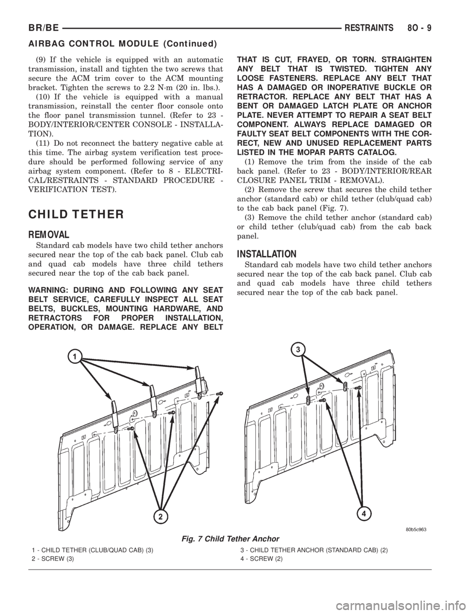
to the cab back panel (Fig. 7).
(3) Remove the child tether anchor (standard cab)
or child tether (club/quad cab) from the cab back
panel.
INSTALLATION
Standard cab models have two child tether anchors
secured near the top of the cab back panel. Club cab
and quad cab models have three child tethers
secured near the top of the cab back panel.
Fig. 7 Child Tether Anchor
1 - CHILD TETHER (CLUB/QUAD CAB) (3)
2 - SCREW (3)3 - CHILD TETHER ANCHOR (STANDARD CAB) (2)
4 - SCREW (2)
BR/BERESTRAINTS 8O - 9
AIRBAG CONTROL MODULE (Continued)
Page 624 of 2255
SPEED CONTROL
TABLE OF CONTENTS
page page
SPEED CONTROL
DESCRIPTION
DESCRIPTION - SPEED CONTROL SYSTEM . 1
DESCRIPTION - VEHICLE SPEED INPUT....2
OPERATION - SPEED CONTROL SYSTEM....2
DIAGNOSIS AND TESTING
DIAGNOSIS AND TESTING - VACUUM
SUPPLY TEST.........................3
DIAGNOSIS AND TESTING - ROAD TEST....4
SPECIFICATIONS
TORQUE - SPEED CONTROL SYSTEM.....4
CABLE
DESCRIPTION..........................4
OPERATION............................4
REMOVAL
REMOVAL - GAS ENGINES...............4
REMOVAL - DIESEL WITH AUTO. TRANS. . . . 5
INSTALLATION
INSTALLATION - GAS ENGINES...........5
INSTALLATION - DIESEL WITH AUTO.
TRANS...............................6SPEED CONTROL SERVO
DESCRIPTION..........................6
OPERATION............................6
REMOVAL
REMOVAL............................6
REMOVAL - DIESEL WITH AUTO. TRANS. . . . 9
INSTALLATION
INSTALLATION.......................11
INSTALLATION - DIESEL WITH AUTO.
TRANS..............................12
SWITCH
DESCRIPTION.........................12
OPERATION...........................12
REMOVAL.............................13
INSTALLATION.........................14
VACUUM RESERVOIR
DESCRIPTION.........................14
REMOVAL.............................14
INSTALLATION.........................15
SPEED CONTROL
DESCRIPTION
DESCRIPTION - SPEED CONTROL SYSTEM
Gas Engines and/or Diesel With Automatic Trans.
The speed control system is operated by the use of
a cable and a vacuum controlled servo. Electronic
control of the speed control system is integrated into
the Powertrain Control Module (PCM). The controls
consist of two steering wheel mounted switches. The
switches are labeled: ON/OFF, RES/ACCEL, SET,
COAST, and CANCEL.
The system is designed to operate at speeds above
30 mph (50 km/h).
WARNING: THE USE OF SPEED CONTROL IS NOT
RECOMMENDED WHEN DRIVING CONDITIONS DO
NOT PERMIT MAINTAINING A CONSTANT SPEED,
SUCH AS IN HEAVY TRAFFIC OR ON ROADS THATARE WINDING, ICY, SNOW COVERED, OR SLIP-
PERY.
Diesel With Manual Trans.
The speed control system is fully electronically con-
trolled by the Engine Control Module (ECM).A
cable and a vacuum controlled servo are not
used if the vehicle is equipped with a manual
transmission and a diesel engine. This is a ser-
vo-less system.The controls consist of two steering
wheel mounted switches. The switches are labeled:
ON/OFF, RES/ACCEL, SET, COAST, and CANCEL.
The system is designed to operate at speeds above
30 mph (50 km/h).
WARNING: THE USE OF SPEED CONTROL IS NOT
RECOMMENDED WHEN DRIVING CONDITIONS DO
NOT PERMIT MAINTAINING A CONSTANT SPEED,
SUCH AS IN HEAVY TRAFFIC OR ON ROADS THAT
ARE WINDING, ICY, SNOW COVERED, OR SLIP-
PERY.
BR/BESPEED CONTROL 8P - 1
Page 625 of 2255

DESCRIPTION - VEHICLE SPEED INPUT
Gas Engines and/or Diesel With Automatic Trans.
The Vehicle Speed Sensor (VSS) is no longer used
for any Dodge Truck.
Vehicle speed and distance covered are measured
by the Rear Wheel Speed Sensor. The sensor is
mounted to the rear axle. A signal is sent from this
sensor to the Controller Antilock Brake (CAB) com-
puter. A signal is then sent from the CAB to the Pow-
ertrain Control Module (PCM) to determine vehicle
speed and distance covered. The PCM will then
determine strategies for speed control system opera-
tion.
Diesel With Manual Trans.
The Vehicle Speed Sensor (VSS) is no longer used
for any Dodge Truck.
Vehicle speed and distance covered are measured
by the Rear Wheel Speed Sensor. The sensor is
mounted to the rear axle. A signal is sent from this
sensor to the Controller Antilock Brake (CAB) com-
puter. A signal is then sent from the CAB to the
Engine Control Module (ECM) to determine vehicle
speed and distance covered. The ECM will then
determine strategies for speed control system opera-
tion.
OPERATION - SPEED CONTROL SYSTEM
Gas Engines and/or Diesel With Automatic Trans.
When speed control is selected by depressing the
ON switch, the PCM allows a set speed to be stored
in PCM RAM for speed control. To store a set speed,
depress the SET switch while the vehicle is moving
at a speed between 35 and 85 mph. In order for the
speed control to engage, the brakes cannot be
applied, nor can the gear selector be indicating the
transmission is in Park or Neutral.
The speed control can be disengaged manually by:
²Stepping on the brake pedal.
²Depressing the OFF switch.
²Depressing the CANCEL switch.
²Depressing the clutch pedal (if equipped).
NOTE: Depressing the OFF switch or turning off the
ignition switch will erase the set speed stored in
the PCM.
For added safety, the speed control system is pro-
grammed to disengage for any of the following condi-
tions:
²An indication of Park or Neutral.
²A rapid increase of rpm (indication that the
clutch has been disengaged).²Excessive engine rpm (indicates that the trans-
mission may be in a low gear).
²The speed signal increases at a rate of 10 mph
per second (indicates that the coefficient of friction
between the road surface and tires is extremely low).
²The speed signal decreases at a rate of 10 mph
per second (indicates that the vehicle may have
decelerated at an extremely high rate).
Once the speed control has been disengaged,
depressing the RES/ACCEL switch (when speed is
greater than 30 mph) restores the vehicle to the tar-
get speed that was stored in the PCM.
While the speed control is engaged, the driver can
increase the vehicle speed by depressing the RES/AC-
CEL switch. The new target speed is stored in the
PCM when the RES/ACCEL is released. The PCM
also has a9tap-up9feature in which vehicle speed
increases at a rate of approximately 2 mph for each
momentary switch activation of the RES/ACCEL
switch.
A ªtap downº feature is used to decelerate without
disengaging the speed control system. To decelerate
from an existing recorded target speed, momentarily
depress the COAST switch. For each switch activa-
tion, speed will be lowered approximately 1 mph.
Diesel With Manual Trans.
When speed control is selected by depressing the
ON switch, the Engine Control Module (ECM) allows
a set speed to be stored in ECM RAM for speed con-
trol. To store a set speed, depress the SET switch
while the vehicle is moving at a speed between 35
and 85 mph. In order for the speed control to engage,
the brakes cannot be applied.The speed control can
be disengaged manually by:
²Stepping on the brake pedal.
²Depressing the OFF switch.
²Depressing the CANCEL switch.
²Depressing the clutch pedal.
NOTE: Depressing the OFF switch or turning off the
ignition switch will erase the set speed stored in
the ECM.
For added safety, the speed control system is pro-
grammed to disengage for any of the following condi-
tions:
²A rapid increase of rpm (indication that the
clutch has been disengaged).
²Excessive engine rpm (indicates that the trans-
mission may be in a low gear).
²The speed signal increases at a rate of 10 mph
per second (indicates that the coefficient of friction
between the road surface and tires is extremely low).
²The speed signal decreases at a rate of 10 mph
per second (indicates that the vehicle may have
decelerated at an extremely high rate).
8P - 2 SPEED CONTROLBR/BE
SPEED CONTROL (Continued)
Page 626 of 2255
Once the speed control has been disengaged,
depressing the RES/ACCEL switch (when speed is
greater than 30 mph) restores the vehicle to the tar-
get speed that was stored in the ECM.
While the speed control is engaged, the driver can
increase the vehicle speed by depressing the RES/AC-
CEL switch. The new target speed is stored in the
ECM when the RES/ACCEL is released. The ECM
also has a9tap-up9feature in which vehicle speed
increases at a rate of approximately 2 mph for each
momentary switch activation of the RES/ACCEL
switch.
A ªtap downº feature is used to decelerate without
disengaging the speed control system. To decelerate
from an existing recorded target speed, momentarily
depress the COAST switch. For each switch activa-
tion, speed will be lowered approximately 1 mph.
DIAGNOSIS AND TESTING
DIAGNOSIS AND TESTING - VACUUM SUPPLY
TEST
Gas Powered Engines
On gasoline powered engines: actual engine vac-
uum, a vacuum reservoir, a one-way check valve and
vacuum lines are used to supply vacuum to the speed
control servo.
(1) Disconnect vacuum hose at speed control servo
and install a vacuum gauge into the disconnected
hose.
(2) Start engine and observe gauge at idle. Vac-
uum gauge should read at least ten inches of mer-
cury.
(3) If vacuum is less than ten inches of mercury,
determine source of leak. Check vacuum line to
engine for leaks. Also check actual engine intake
manifold vacuum. If manifold vacuum does not meet
this requirement, check for poor engine performance
and repair as necessary.
(4) If vacuum line to engine is not leaking, check
for leak at vacuum reservoir. To locate and gain
access to reservoir, refer to Vacuum Reservoir Remov-
al/Installation in this group. Disconnect vacuum line
at reservoir and connect a hand-operated vacuum
pump to reservoir fitting. Apply vacuum. Reservoir
vacuum should not bleed off. If vacuum is being lost,
replace reservoir.
(5) Verify operation of one-way check valve and
check it for leaks.
(a) Locate one-way check valve. The valve is
located in vacuum line between vacuum reservoirand engine vacuum source. Disconnect vacuum
hoses (lines) at each end of valve.
(b) Connect a hand-operated vacuum pump to
reservoir end of check valve. Apply vacuum. Vac-
uum should not bleed off. If vacuum is being lost,
replace one-way check valve.
(c) Connect a hand-operated vacuum pump to
vacuum source end of check valve. Apply vacuum.
Vacuum should flow through valve. If vacuum is
not flowing, replace one-way check valve. Seal the
fitting at opposite end of valve with a finger and
apply vacuum. If vacuum will not hold, diaphragm
within check valve has ruptured. Replace valve.
Diesel Engines With Automatic Trans.
On diesel powered engines equipped with an auto-
matic transmission: an engine driven vacuum pump,
a one-way check valve and vacuum lines are used to
supply vacuum to the speed control servo. A vacuum
reservoir is not used.
(1) Disconnect vacuum hose at speed control servo
and install a vacuum gauge into the disconnected
hose.
(2) Start engine and observe gauge at idle. For
vacuum testing and vacuum specifications, refer to
Vacuum Pump OutputÐDiesel Engine in 9, Engines.
(3) If vacuum pump output is OK, determine other
source of leak. Check all vacuum lines to: speed con-
trol servo, engine vacuum pump and heating/air con-
ditioning system for leaks.
(4) Verify operation of one-way check valve and
check it for leaks.
(a) Locate one-way check valve. The valve is
located in vacuum line between speed control servo
and engine vacuum pump. Disconnect vacuum
hoses (lines) at each end of valve.
(b) Connect a hand-operated vacuum pump to
reservoir end of check valve. Apply vacuum. Vac-
uum should not bleed off. If vacuum is being lost,
replace one-way check valve.
(c) Connect a hand-operated vacuum pump to
vacuum source end of check valve. Apply vacuum.
Vacuum should flow through valve. If vacuum is
not flowing, replace one-way check valve. Seal the
fitting at opposite end of valve with a finger and
apply vacuum. If vacuum will not hold, diaphragm
within check valve has ruptured. Replace valve.
Diesel Engine With Manual Trans.
Vacuum is not used for any part of the speed con-
trol system if equipped with a diesel engine and a
manual transmission.
BR/BESPEED CONTROL 8P - 3
SPEED CONTROL (Continued)
Page 657 of 2255
cover/grille panel to drive the wiper arms and blades
are the only visible components of the wiper module.
The wiper module consists of the following major
components:
²Bracket- The wiper module bracket consists of
a long tubular steel main member that has a
stamped pivot bracket formation near each end
where the two wiper pivots are secured. A stamped
steel mounting plate for the wiper motor is secured
with welds near the center of the main member.
²Crank Arm- The wiper motor crank arm is a
stamped steel unit that has a slotted hole on the
driven end that is secured to the wiper motor output
shaft with a nut, and has a ball stud secured to the
drive end.
²Linkage- The two wiper linkage members are
each constructed of stamped steel. A driver side drive
link with a plastic socket-type bushing in the left
end, and a plastic sleeve-type bushing in the right
end. Socket bushing is snap-fit over the pivot ball
stud on the left pivot, while the sleeve bushing is fit
over the longer wiper motor crank arm pivot stud.
The passenger side drive link has a plastic socket-
type bushing on each end. One end of this drive link
is snap-fit over the pivot ball stud on the right pivot,
while the other end is snap-fit over the exposed end
of the longer ball stud on the wiper motor crank arm.
²Motor- The wiper motor is secured with three
screws to the motor mounting plate near the center
of the wiper module bracket. The wiper motor output
shaft passes through a hole in the module bracket,
where a nut secures the wiper motor crank arm to
the motor output shaft. The two-speed permanent
magnet wiper motor features an integral transmis-
sion, an internal park switch, and an internal Posi-
tive Temperature Coefficient (PTC) circuit breaker.
²Pivots- The two wiper pivots are secured to the
ends of the wiper module bracket. The crank arms
that extend from the bottom of the pivot shafts each
have a ball stud on their end. The upper end of each
pivot shaft where the wiper arms will be fastened
each has an externally serrated drum secured to it.
The wiper module cannot be adjusted or repaired.
If any component of the module is faulty or damaged,
the entire wiper module unit must be replaced.
OPERATION
The wiper module operation is controlled by the
vehicle operator through battery current inputs
received by the wiper motor from the multi-function
switch on the steering column. The wiper motor
speed is controlled by current flow to either the low
speed or the high speed set of brushes. The park
switch is a single pole, single throw, momentary
switch within the wiper motor that is mechanically
actuated by the wiper motor transmission compo-nents. The park switch alternately closes the wiper
park switch sense circuit to ground or to battery cur-
rent, depending upon the position of the wipers on
the glass. This feature allows the motor to complete
its current wipe cycle after the wiper system has
been turned Off, and to park the wiper blades in the
lowest portion of the wipe pattern. The automatic
resetting circuit breaker protects the motor from
overloads. The wiper motor crank arm, the two wiper
linkage members, and the two wiper pivots mechan-
ically convert the rotary output of the wiper motor to
the back and forth wiping motion of the wiper arms
and blades on the glass.
REMOVAL
(1) Disconnect and isolate the battery negative
cable.
(2) Remove the wiper arms from the wiper pivots.
(Refer to 8 - ELECTRICAL/WIPERS/WASHERS/
WIPER ARMS - REMOVAL).
(3) Remove the cowl plenum cover/grille panel
from the cowl plenum. (Refer to 23 - BODY/EXTERI-
OR/COWL GRILLE - REMOVAL).
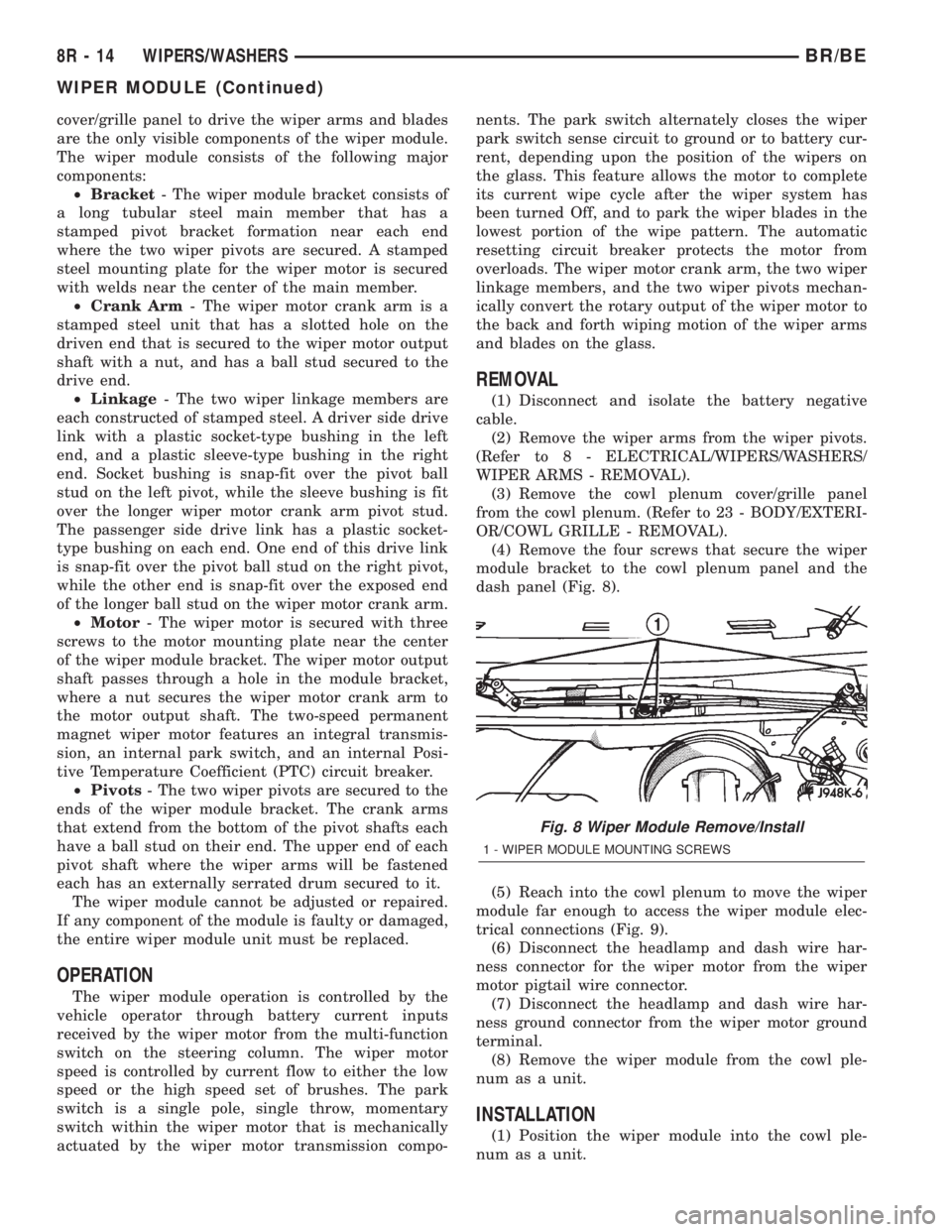
(4) Remove the four screws that secure the wiper
module bracket to the cowl plenum panel and the
dash panel (Fig. 8).
(5) Reach into the cowl plenum to move the wiper
module far enough to access the wiper module elec-
trical connections (Fig. 9).
(6) Disconnect the headlamp and dash wire har-
ness connector for the wiper motor from the wiper
motor pigtail wire connector.
(7) Disconnect the headlamp and dash wire har-
ness ground connector from the wiper motor ground
terminal.
(8) Remove the wiper module from the cowl ple-
num as a unit.
INSTALLATION
(1) Position the wiper module into the cowl ple-
num as a unit.
Fig. 8 Wiper Module Remove/Install
1 - WIPER MODULE MOUNTING SCREWS
8R - 14 WIPERS/WASHERSBR/BE
WIPER MODULE (Continued)
Page 667 of 2255

SYMBOLS
International symbols are used throughout the wir-
ing diagrams. These symbols are consistent with
those being used around the world (Fig. 3).
TERMINOLOGY
This is a list of terms and definitions used in the
wiring diagrams.
LHD .................Left Hand Drive Vehicles
RHD................Right Hand Drive Vehicles
ATX . . Automatic Transmissions-Front Wheel Drive
MTX....Manual Transmissions-Front Wheel Drive
AT ....Automatic Transmissions-Rear Wheel Drive
MT .....Manual Transmissions-Rear Wheel Drive
SOHC...........Single Over Head Cam Engine
DOHC..........Double Over Head Cam Engine
Built-Up-Export........ Vehicles Built For Sale In
Markets Other Than North America
Except-Built-Up-Export . . Vehicles Built For Sale In
North America
DESCRIPTION - CIRCUIT INFORMATION
Each wire shown in the diagrams contains a code
which identifies the main circuit, part of the main
circuit, gage of wire, and color (Fig. 4).
WIRE COLOR CODE CHART
COLOR CODE COLOR
BL BLUE
BK BLACK
BR BROWN
DB DARK BLUE
DG DARK GREEN
GY GRAY
LB LIGHT BLUE
LG LIGHT GREEN
OR ORANGE
PK PINK
RD RED
TN TAN
VT VIOLET
WT WHITE
YL YELLOW
* WITH TRACER
DESCRIPTION - CIRCUIT FUNCTIONS
All circuits in the diagrams use an alpha/numeric
code to identify the wire and it's function. To identify
which circuit code applies to a system, refer to the
Circuit Identification Code Chart. This chart shows
the main circuits only and does not show the second-
ary codes that may apply to some models.
CIRCUIT IDENTIFICATION CODE CHART
CIRCUIT FUNCTION
A BATTERY FEED
B BRAKE CONTROLS
C CLIMATE CONTROLS
D DIAGNOSTIC CIRCUITS
E DIMMING ILLUMINATION
CIRCUITS
F FUSED CIRCUITS
G MONITORING CIRCUITS
(GAUGES)
H OPEN
I NOT USED
J OPEN
K POWERTRAIN CONTROL
MODULE
L EXTERIOR LIGHTING
M INTERIOR LIGHTING
N NOT USED
O NOT USED
P POWER OPTION (BATTERY
FEED)
Q POWER OPTIONS (IGNITION
FEED)
R PASSIVE RESTRAINT
S SUSPENSION/STEERING
T TRANSMISSION/TRANSAXLE/
TRANSFER CASE
U OPEN
V SPEED CONTROL, WIPER/
WASHER
W OPEN
X AUDIO SYSTEMS
Y OPEN
Z GROUNDS
8W - 01 - 4 8W-01 WIRING DIAGRAM INFORMATIONBR/BE
WIRING DIAGRAM INFORMATION (Continued)
Page 670 of 2255
WARNINGS - GENERAL
WARNINGSprovide information to prevent per-
sonal injury and vehicle damage. Below is a list of
general warnings that should be followed any time a
vehicle is being serviced.
WARNING:: ALWAYS WEAR SAFETY GLASSES FOR
EYE PROTECTION.
WARNING: USE SAFETY STANDS ANYTIME A PRO-
CEDURE REQUIRES BEING UNDER A VEHICLE.
WARNING: BE SURE THAT THE IGNITION SWITCH
ALWAYS IS IN THE OFF POSITION, UNLESS THE
PROCEDURE REQUIRES IT TO BE ON.
WARNING: SET THE PARKING BRAKE WHEN
WORKING ON ANY VEHICLE. AN AUTOMATIC
TRANSMISSION SHOULD BE IN PARK. A MANUAL
TRANSMISSION SHOULD BE IN NEUTRAL.
WARNING: OPERATE THE ENGINE ONLY IN A
WELL-VENTILATED AREA.
WARNING: KEEP AWAY FROM MOVING PARTS
WHEN THE ENGINE IS RUNNING, ESPECIALLY THE
FAN AND BELTS.
WARNING: TO PREVENT SERIOUS BURNS, AVOID
CONTACT WITH HOT PARTS SUCH AS THE RADIA-
TOR, EXHAUST MANIFOLD(S), TAIL PIPE, CATA-
LYTIC CONVERTER AND MUFFLER.
WARNING: DO NOT ALLOW FLAME OR SPARKS
NEAR THE BATTERY. GASES ARE ALWAYS
PRESENT IN AND AROUND THE BATTERY.
WARNING: ALWAYS REMOVE RINGS, WATCHES,
LOOSE HANGING JEWELRY AND AVOID LOOSE
CLOTHING.
DIAGNOSIS AND TESTING - WIRING HARNESS
TROUBLESHOOTING TOOLS
When diagnosing a problem in an electrical circuit
there are several common tools necessary. These tools
are listed and explained below.
²Jumper Wire - This is a test wire used to con-
nect two points of a circuit. It can be used to bypass
an open in a circuit.WARNING: NEVER USE A JUMPER WIRE ACROSS
A LOAD, SUCH AS A MOTOR, CONNECTED
BETWEEN A BATTERY FEED AND GROUND.
²Voltmeter - Used to check for voltage on a cir-
cuit. Always connect the black lead to a known good
ground and the red lead to the positive side of the
circuit.
CAUTION: Most of the electrical components used
in today's vehicles are Solid State. When checking
voltages in these circuits, use a meter with a 10 -
megohm or greater impedance rating.
²Ohmmeter - Used to check the resistance
between two points of a circuit. Low or no resistance
in a circuit means good continuity.
CAUTION: Most of the electrical components used
in today's vehicles are Solid State. When checking
resistance in these circuits use a meter with a 10 -
megohm or greater impedance rating. In addition,
make sure the power is disconnected from the cir-
cuit. Circuits that are powered up by the vehicle's
electrical system can cause damage to the equip-
ment and provide false readings.
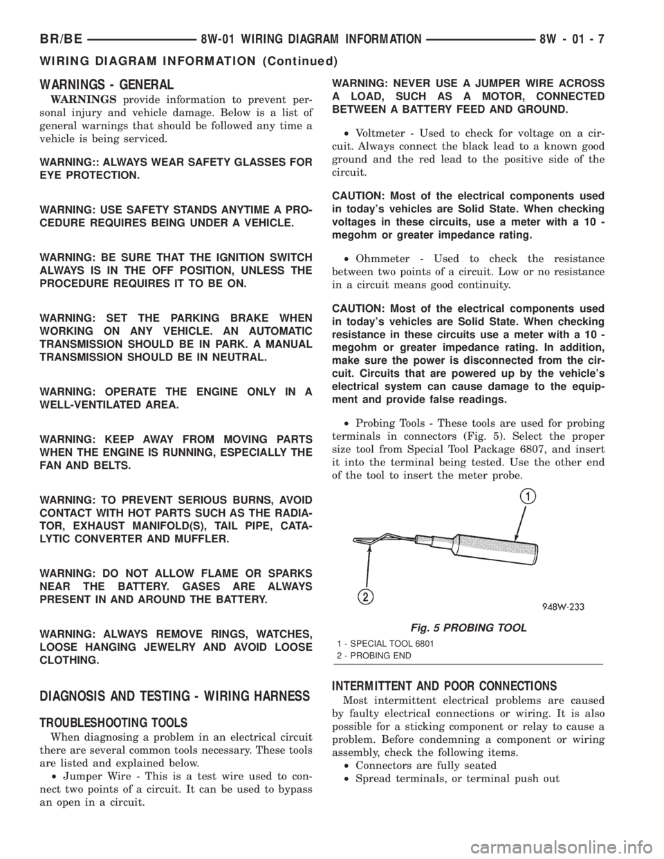
²Probing Tools - These tools are used for probing
terminals in connectors (Fig. 5). Select the proper
size tool from Special Tool Package 6807, and insert
it into the terminal being tested. Use the other end
of the tool to insert the meter probe.
INTERMITTENT AND POOR CONNECTIONS
Most intermittent electrical problems are caused
by faulty electrical connections or wiring. It is also
possible for a sticking component or relay to cause a
problem. Before condemning a component or wiring
assembly, check the following items.
²Connectors are fully seated
²Spread terminals, or terminal push out
Fig. 5 PROBING TOOL
1 - SPECIAL TOOL 6801
2 - PROBING END
BR/BE8W-01 WIRING DIAGRAM INFORMATION 8W - 01 - 7
WIRING DIAGRAM INFORMATION (Continued)