2002 DODGE RAM battery
[x] Cancel search: batteryPage 1365 of 2255
(d) Tighten sensor to 2±3 N´m (15±20 in. lbs.)
torque.
(e) Connect electrical connector to WIF sensor.
(f) Install fuel filter. Refer to previous steps.
(4)Fuel Heater Element:
(a) Do not install fuel filter until heater element
is installed.
(b) Position heater element into filter housing
(fingers downward). Lock fingers into housing.
(c) Install new o-ring to electrical connector
(where connector passes through filter housing).
Apply a light film of clean diesel oil to o-ring seal.
Press this connector into filter housing until it
snaps into heater element.
(d) Install temperature sensor housing and 2
mounting screws to fuel filter housing.
(e) Connect electrical connector.
(f) Install fuel filter. Refer to previous steps.
(5)Drain Valve:
(a) Install 2 new o-rings to valve and filter hous-
ing.
(b) Apply a light film of clean diesel oil to both
seals.
(c) Position valve to filter housing.
(d) Install 4 mounting screws and tighten to 3±5
N´m (30±40 in. lbs.) torque.
(e) Connect drain hose to drain valve.
(f) Install fuel filter. Refer to previous steps.
(6) Start engine and check for leaks.
FUEL HEATER
DESCRIPTION
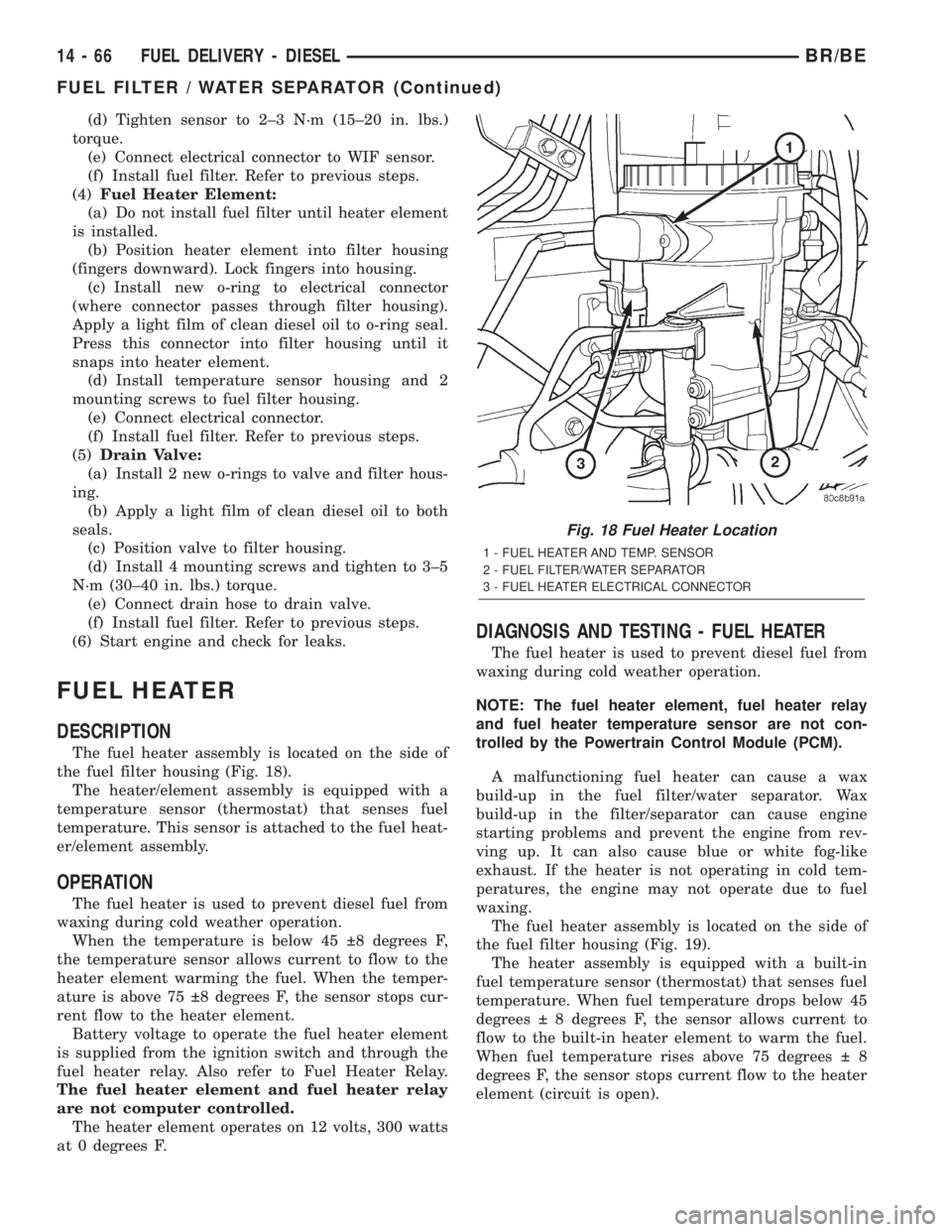
The fuel heater assembly is located on the side of
the fuel filter housing (Fig. 18).
The heater/element assembly is equipped with a
temperature sensor (thermostat) that senses fuel
temperature. This sensor is attached to the fuel heat-
er/element assembly.
OPERATION
The fuel heater is used to prevent diesel fuel from
waxing during cold weather operation.
When the temperature is below 45 8 degrees F,
the temperature sensor allows current to flow to the
heater element warming the fuel. When the temper-
ature is above 75 8 degrees F, the sensor stops cur-
rent flow to the heater element.
Battery voltage to operate the fuel heater element
is supplied from the ignition switch and through the
fuel heater relay. Also refer to Fuel Heater Relay.
The fuel heater element and fuel heater relay
are not computer controlled.
The heater element operates on 12 volts, 300 watts
at 0 degrees F.
DIAGNOSIS AND TESTING - FUEL HEATER
The fuel heater is used to prevent diesel fuel from
waxing during cold weather operation.
NOTE: The fuel heater element, fuel heater relay
and fuel heater temperature sensor are not con-
trolled by the Powertrain Control Module (PCM).
A malfunctioning fuel heater can cause a wax
build-up in the fuel filter/water separator. Wax
build-up in the filter/separator can cause engine
starting problems and prevent the engine from rev-
ving up. It can also cause blue or white fog-like
exhaust. If the heater is not operating in cold tem-
peratures, the engine may not operate due to fuel
waxing.
The fuel heater assembly is located on the side of
the fuel filter housing (Fig. 19).
The heater assembly is equipped with a built-in
fuel temperature sensor (thermostat) that senses fuel
temperature. When fuel temperature drops below 45
degrees 8 degrees F, the sensor allows current to
flow to the built-in heater element to warm the fuel.
When fuel temperature rises above 75 degrees 8
degrees F, the sensor stops current flow to the heater
element (circuit is open).
Fig. 18 Fuel Heater Location
1 - FUEL HEATER AND TEMP. SENSOR
2 - FUEL FILTER/WATER SEPARATOR
3 - FUEL HEATER ELECTRICAL CONNECTOR
14 - 66 FUEL DELIVERY - DIESELBR/BE
FUEL FILTER / WATER SEPARATOR (Continued)
Page 1366 of 2255
Voltage to operate the fuel heater element is sup-
plied from the ignition switch, through the fuel
heater relay (also refer to Fuel Heater Relay), to the
fuel temperature sensor and on to the fuel heater ele-
ment.
The heater element operates on 12 volts, 300 watts
at 0 degrees F. As temperature increases, power
requirements decrease.
A minimum of 7 volts is required to operate the
fuel heater. The resistance value of the heater ele-
ment is less than 1 ohm (cold) and up to 1000 ohms
warm.
TESTING
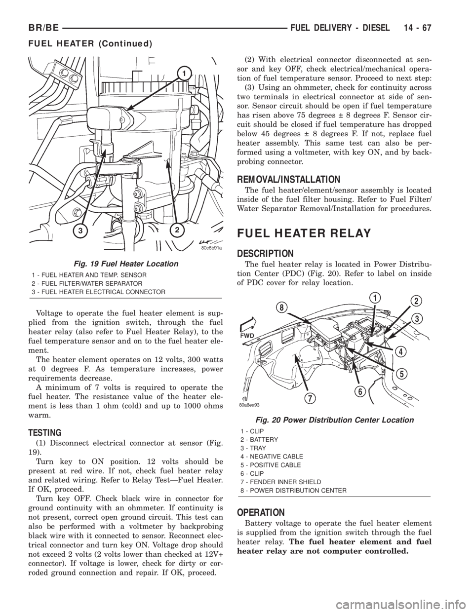
(1) Disconnect electrical connector at sensor (Fig.
19).
Turn key to ON position. 12 volts should be
present at red wire. If not, check fuel heater relay
and related wiring. Refer to Relay TestÐFuel Heater.
If OK, proceed.
Turn key OFF. Check black wire in connector for
ground continuity with an ohmmeter. If continuity is
not present, correct open ground circuit. This test can
also be performed with a voltmeter by backprobing
black wire with it connected to sensor. Reconnect elec-
trical connector and turn key ON. Voltage drop should
not exceed 2 volts (2 volts lower than checked at 12V+
connector). If voltage is lower, check for dirty or cor-
roded ground connection and repair. If OK, proceed.
(2) With electrical connector disconnected at sen-
sor and key OFF, check electrical/mechanical opera-
tion of fuel temperature sensor. Proceed to next step:
(3) Using an ohmmeter, check for continuity across
two terminals in electrical connector at side of sen-
sor. Sensor circuit should be open if fuel temperature
has risen above 75 degrees 8 degrees F. Sensor cir-
cuit should be closed if fuel temperature has dropped
below 45 degrees 8 degrees F. If not, replace fuel
heater assembly. This same test can also be per-
formed using a voltmeter, with key ON, and by back-
probing connector.
REMOVAL/INSTALLATION
The fuel heater/element/sensor assembly is located
inside of the fuel filter housing. Refer to Fuel Filter/
Water Separator Removal/Installation for procedures.
FUEL HEATER RELAY
DESCRIPTION
The fuel heater relay is located in Power Distribu-
tion Center (PDC) (Fig. 20). Refer to label on inside
of PDC cover for relay location.
OPERATION
Battery voltage to operate the fuel heater element
is supplied from the ignition switch through the fuel
heater relay.The fuel heater element and fuel
heater relay are not computer controlled.
Fig. 19 Fuel Heater Location
1 - FUEL HEATER AND TEMP. SENSOR
2 - FUEL FILTER/WATER SEPARATOR
3 - FUEL HEATER ELECTRICAL CONNECTOR
Fig. 20 Power Distribution Center Location
1 - CLIP
2 - BATTERY
3 - TRAY
4 - NEGATIVE CABLE
5 - POSITIVE CABLE
6 - CLIP
7 - FENDER INNER SHIELD
8 - POWER DISTRIBUTION CENTER
BR/BEFUEL DELIVERY - DIESEL 14 - 67
FUEL HEATER (Continued)
Page 1367 of 2255
DIAGNOSIS AND TESTING - FUEL HEATER
RELAY
The fuel heater relay is located in the Power Dis-
tribution Center (PDC). Refer to label under PDC
cover for relay location.
To test the fuel heater, refer to Fuel Heater Test.
To test the heater relay only, refer to following:
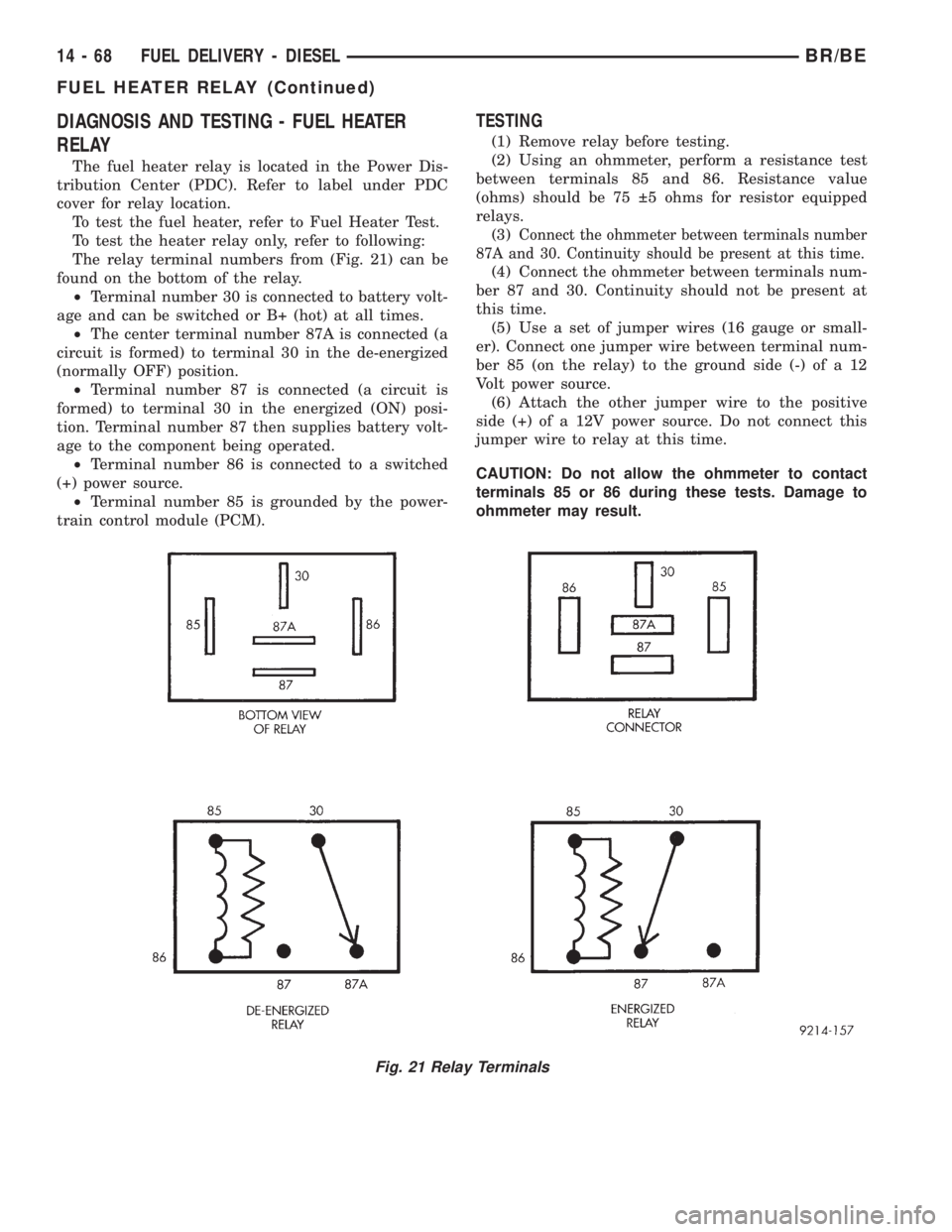
The relay terminal numbers from (Fig. 21) can be
found on the bottom of the relay.
²Terminal number 30 is connected to battery volt-
age and can be switched or B+ (hot) at all times.
²The center terminal number 87A is connected (a
circuit is formed) to terminal 30 in the de-energized
(normally OFF) position.
²Terminal number 87 is connected (a circuit is
formed) to terminal 30 in the energized (ON) posi-
tion. Terminal number 87 then supplies battery volt-
age to the component being operated.
²Terminal number 86 is connected to a switched
(+) power source.
²Terminal number 85 is grounded by the power-
train control module (PCM).
TESTING
(1) Remove relay before testing.
(2) Using an ohmmeter, perform a resistance test
between terminals 85 and 86. Resistance value
(ohms) should be 75 5 ohms for resistor equipped
relays.
(3)
Connect the ohmmeter between terminals number
87A and 30. Continuity should be present at this time.
(4) Connect the ohmmeter between terminals num-
ber 87 and 30. Continuity should not be present at
this time.
(5) Use a set of jumper wires (16 gauge or small-
er). Connect one jumper wire between terminal num-
ber 85 (on the relay) to the ground side (-) of a 12
Volt power source.
(6) Attach the other jumper wire to the positive
side (+) of a 12V power source. Do not connect this
jumper wire to relay at this time.
CAUTION: Do not allow the ohmmeter to contact
terminals 85 or 86 during these tests. Damage to
ohmmeter may result.
Fig. 21 Relay Terminals
14 - 68 FUEL DELIVERY - DIESELBR/BE
FUEL HEATER RELAY (Continued)
Page 1368 of 2255
(7) Attach the other jumper wire (12V +) to termi-
nal number 86. This will activate the relay. Continu-
ity should now be present between terminals number
87 and 30. Continuity should not be present between
terminals number 87A and 30.
(8) Disconnect jumper wires from relay and 12 Volt
power source.
(9) If continuity or resistance tests did not pass,
replace relay. If tests passed, refer to 8, Wiring Dia-
grams for (fuel system) relay wiring schematics and
for additional circuit information.
REMOVAL
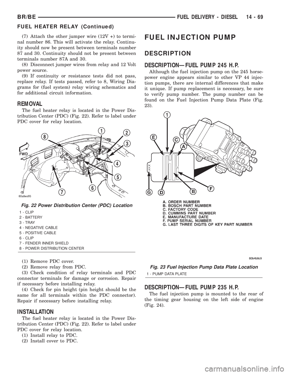
The fuel heater relay is located in the Power Dis-
tribution Center (PDC) (Fig. 22). Refer to label under
PDC cover for relay location.
(1) Remove PDC cover.
(2) Remove relay from PDC.
(3) Check condition of relay terminals and PDC
connector terminals for damage or corrosion. Repair
if necessary before installing relay.
(4) Check for pin height (pin height should be the
same for all terminals within the PDC connector).
Repair if necessary before installing relay.
INSTALLATION
The fuel heater relay is located in the Power Dis-
tribution Center (PDC) (Fig. 22). Refer to label under
PDC cover for relay location.
(1) Install relay to PDC.
(2) Install cover to PDC.
FUEL INJECTION PUMP
DESCRIPTION
DESCRIPTIONÐFUEL PUMP 245 H.P.
Although the fuel injection pump on the 245 horse-
power engine appears similar to other VP 44 injec-
tion pumps, there are internal differences that make
it unique. If pump replacement is necessary, be sure
to verify pump number. The pump number can be
found on the Fuel Injection Pump Data Plate (Fig.
23).
DESCRIPTIONÐFUEL PUMP 235 H.P.
The fuel injection pump is mounted to the rear of
the timing gear housing on the left side of engine
(Fig. 24).
Fig. 22 Power Distribution Center (PDC) Location
1 - CLIP
2 - BATTERY
3 - TRAY
4 - NEGATIVE CABLE
5 - POSITIVE CABLE
6 - CLIP
7 - FENDER INNER SHIELD
8 - POWER DISTRIBUTION CENTER
Fig. 23 Fuel Injection Pump Data Plate Location
1 - PUMP DATA PLATE
BR/BEFUEL DELIVERY - DIESEL 14 - 69
FUEL HEATER RELAY (Continued)
Page 1371 of 2255
(1) Remove hose clamp and crankcase vent hose at
crankcase breather (Fig. 26). Remove crankcase
breather from gear cover. Breather threads into
cover.
(2) Remove injection pump nut and washer (Fig.
27). Locate keyway behind washer.
(3) Be sure keyway aligning fuel injection pump
shaft to injection pump gear is in proper position and
pump gear has not slipped on pump shaft.
The following steps will require removing timing
gear cover to gain access to timing gears. Refer to
Group 9, Engines for procedures.
(4) Use a T-type puller to separate injection pump
gear from pump shaft.
(5) Be sure keyway has been installed with arrow
pointed torearof pump (Fig. 28).
(6)Pump timing has been calibrated to pump
keyway. Be sure 3±digit number on pump key-
way (Fig. 28) matches 3±digit number on fuel
injection pump data plate. Plate is located on
side of injection pump (Fig. 29). Twenty±one dif-
ferent calibrated keyways/pumps are available.
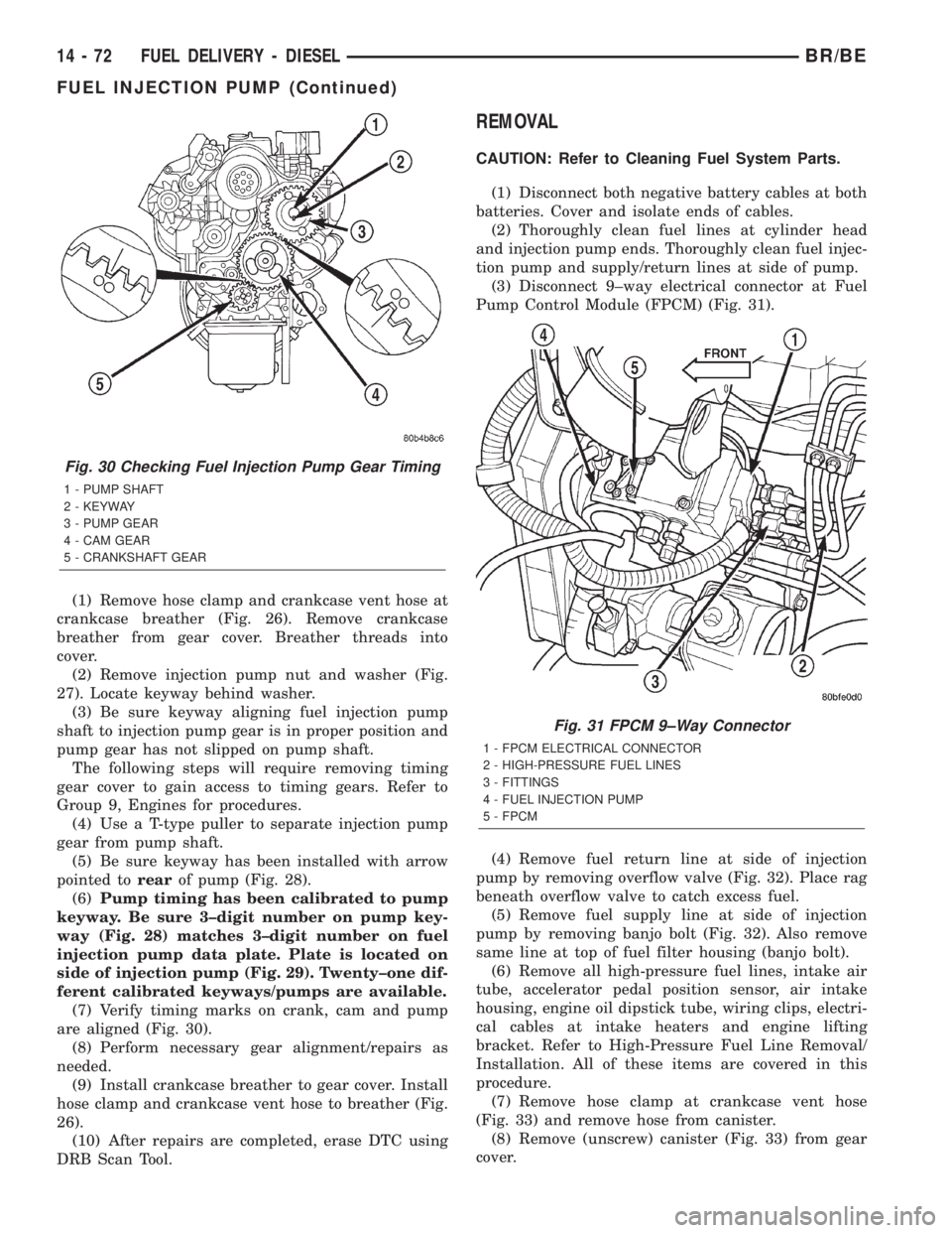
(7) Verify timing marks on crank, cam and pump
are aligned (Fig. 30).
(8) Perform necessary gear alignment/repairs as
needed.
(9) Install crankcase breather to gear cover. Install
hose clamp and crankcase vent hose to breather (Fig.
26).
(10) After repairs are completed, erase DTC using
DRB Scan Tool.
REMOVAL
CAUTION: Refer to Cleaning Fuel System Parts.
(1) Disconnect both negative battery cables at both
batteries. Cover and isolate ends of cables.
(2) Thoroughly clean fuel lines at cylinder head
and injection pump ends. Thoroughly clean fuel injec-
tion pump and supply/return lines at side of pump.
(3) Disconnect 9±way electrical connector at Fuel
Pump Control Module (FPCM) (Fig. 31).
(4) Remove fuel return line at side of injection
pump by removing overflow valve (Fig. 32). Place rag
beneath overflow valve to catch excess fuel.
(5) Remove fuel supply line at side of injection
pump by removing banjo bolt (Fig. 32). Also remove
same line at top of fuel filter housing (banjo bolt).
(6) Remove all high-pressure fuel lines, intake air
tube, accelerator pedal position sensor, air intake
housing, engine oil dipstick tube, wiring clips, electri-
cal cables at intake heaters and engine lifting
bracket. Refer to High-Pressure Fuel Line Removal/
Installation. All of these items are covered in this
procedure.
(7) Remove hose clamp at crankcase vent hose
(Fig. 33) and remove hose from canister.
(8) Remove (unscrew) canister (Fig. 33) from gear
cover.
Fig. 30 Checking Fuel Injection Pump Gear Timing
1 - PUMP SHAFT
2 - KEYWAY
3 - PUMP GEAR
4 - CAM GEAR
5 - CRANKSHAFT GEAR
Fig. 31 FPCM 9±Way Connector
1 - FPCM ELECTRICAL CONNECTOR
2 - HIGH-PRESSURE FUEL LINES
3 - FITTINGS
4 - FUEL INJECTION PUMP
5 - FPCM
14 - 72 FUEL DELIVERY - DIESELBR/BE
FUEL INJECTION PUMP (Continued)
Page 1375 of 2255
The machined tapers on both injection pump
shaft and injection pump gear (Fig. 42) must be
absolutely dry, clean and free of any dirt or oil
film. This will ensure proper gear-to-shaft tight-
ening.
(5) Clean pump gear and pump shaft at machined
tapers (Fig. 42) with an evaporative type cleaner
such as brake cleaner.
Keyway Installation:
(6) The pump/gear keyway has an arrow and a
3±digit number stamped at top edge (Fig. 41). Posi-
tion keyway into pump shaft witharrow pointed to
rear of pump.Also be sure 3±digit number stamped
to top of keyway is same as 3±digit number stamped
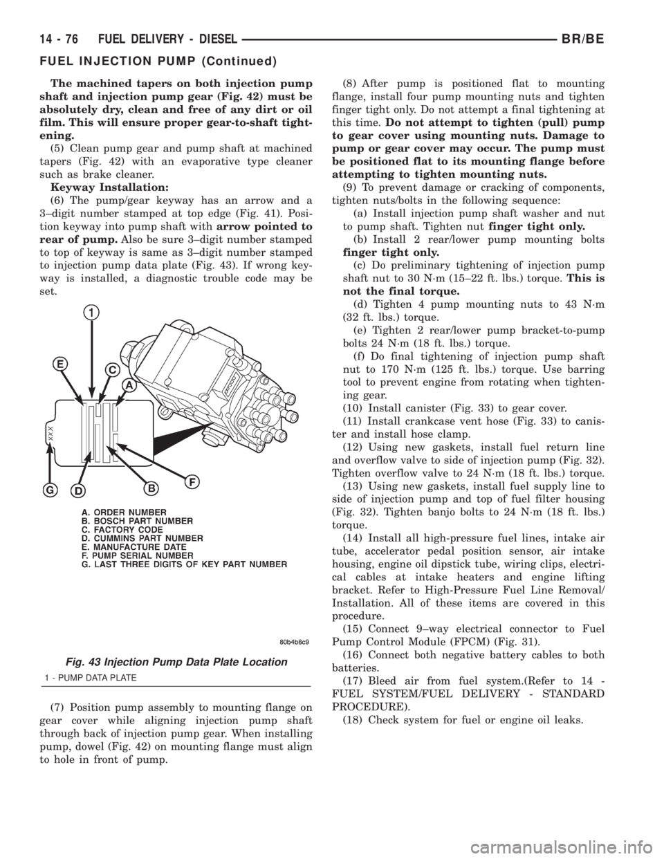
to injection pump data plate (Fig. 43). If wrong key-
way is installed, a diagnostic trouble code may be
set.
(7) Position pump assembly to mounting flange on
gear cover while aligning injection pump shaft
through back of injection pump gear. When installing
pump, dowel (Fig. 42) on mounting flange must align
to hole in front of pump.(8) After pump is positioned flat to mounting
flange, install four pump mounting nuts and tighten
finger tight only. Do not attempt a final tightening at
this time.Do not attempt to tighten (pull) pump
to gear cover using mounting nuts. Damage to
pump or gear cover may occur. The pump must
be positioned flat to its mounting flange before
attempting to tighten mounting nuts.
(9) To prevent damage or cracking of components,
tighten nuts/bolts in the following sequence:
(a) Install injection pump shaft washer and nut
to pump shaft. Tighten nutfinger tight only.
(b) Install 2 rear/lower pump mounting bolts
finger tight only.
(c) Do preliminary tightening of injection pump
shaft nut to 30 N´m (15±22 ft. lbs.) torque.This is
not the final torque.
(d) Tighten 4 pump mounting nuts to 43 N´m
(32 ft. lbs.) torque.
(e) Tighten 2 rear/lower pump bracket-to-pump
bolts 24 N´m (18 ft. lbs.) torque.
(f) Do final tightening of injection pump shaft
nut to 170 N´m (125 ft. lbs.) torque. Use barring
tool to prevent engine from rotating when tighten-
ing gear.
(10) Install canister (Fig. 33) to gear cover.
(11) Install crankcase vent hose (Fig. 33) to canis-
ter and install hose clamp.
(12) Using new gaskets, install fuel return line
and overflow valve to side of injection pump (Fig. 32).
Tighten overflow valve to 24 N´m (18 ft. lbs.) torque.
(13) Using new gaskets, install fuel supply line to
side of injection pump and top of fuel filter housing
(Fig. 32). Tighten banjo bolts to 24 N´m (18 ft. lbs.)
torque.
(14) Install all high-pressure fuel lines, intake air
tube, accelerator pedal position sensor, air intake
housing, engine oil dipstick tube, wiring clips, electri-
cal cables at intake heaters and engine lifting
bracket. Refer to High-Pressure Fuel Line Removal/
Installation. All of these items are covered in this
procedure.
(15) Connect 9±way electrical connector to Fuel
Pump Control Module (FPCM) (Fig. 31).
(16) Connect both negative battery cables to both
batteries.
(17) Bleed air from fuel system.(Refer to 14 -
FUEL SYSTEM/FUEL DELIVERY - STANDARD
PROCEDURE).
(18) Check system for fuel or engine oil leaks.
Fig. 43 Injection Pump Data Plate Location
1 - PUMP DATA PLATE
14 - 76 FUEL DELIVERY - DIESELBR/BE
FUEL INJECTION PUMP (Continued)
Page 1376 of 2255
FUEL INJECTION PUMP DATA
PLATE
SPECIFICATIONS
FUEL INJECTION PUMP DATA PLATE
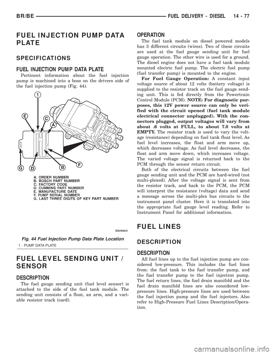
Pertinent information about the fuel injection
pump is machined into a boss on the drivers side of
the fuel injection pump (Fig. 44).
FUEL LEVEL SENDING UNIT /
SENSOR
DESCRIPTION
The fuel gauge sending unit (fuel level sensor) is
attached to the side of the fuel tank module. The
sending unit consists of a float, an arm, and a vari-
able resistor track (card).
OPERATION
The fuel tank module on diesel powered models
has 3 different circuits (wires). Two of these circuits
are used at the fuel gauge sending unit for fuel
gauge operation. The other wire is used for a ground.
The diesel engine does not have a fuel tank module
mounted electric fuel pump. The electric fuel pump
(fuel transfer pump) is mounted to the engine.
For Fuel Gauge Operation:A constant input
voltage source of about 12 volts (battery voltage) is
supplied to the resistor track on the fuel gauge send-
ing unit. This is fed directly from the Powertrain
Control Module (PCM).NOTE: For diagnostic pur-
poses, this 12V power source can only be veri-
fied with the circuit opened (fuel tank module
electrical connector unplugged). With the con-
nectors plugged, output voltages will vary from
about .6 volts at FULL, to about 7.0 volts at
EMPTY.The resistor track is used to vary the volt-
age (resistance) depending on fuel tank float level. As
fuel level increases, the float and arm move up,
which decreases voltage. As fuel level decreases, the
float and arm move down, which increases voltage.
The varied voltage signal is returned back to the
PCM through the sensor return circuit.
Both of the electrical circuits between the fuel
gauge sending unit and the PCM are hard-wired (not
multi-plexed). After the voltage signal is sent from
the resistor track, and back to the PCM, the PCM
will interpret the resistance (voltage) data and send
a message across the multi-plex bus circuits to the
instrument panel cluster. Here it is translated into
the appropriate fuel gauge level reading. Refer to
Instrument Panel for additional information.
FUEL LINES
DESCRIPTION
DESCRIPTION
All fuel lines up to the fuel injection pump are con-
sidered low-pressure. This includes the fuel lines
from: the fuel tank to the fuel transfer pump, and
the fuel transfer pump to the fuel injection pump.
The fuel return lines, the fuel drain manifold and the
fuel drain manifold lines are also considered low-
pressure lines. High-pressure lines are used between
the fuel injection pump and the fuel injectors. Also
refer to High-Pressure Fuel Lines Description/Opera-
tion.
Fig. 44 Fuel Injection Pump Data Plate Location
1 - PUMP DATA PLATE
BR/BEFUEL DELIVERY - DIESEL 14 - 77
Page 1378 of 2255
CAUTION: The high-pressure fuel lines must be
clamped securely in place in the holders. The lines
cannot contact each other or other components. Do
not attempt to weld high-pressure fuel lines or to
repair lines that are damaged. Only use the recom-
mended lines when replacement of high-pressure
fuel line is necessary.
REMOVAL
High-pressure lines are used between the fuel
injection pump and the fuel injectors only. All high-
pressure fuel lines are of the same length and inside
diameter. Correct high-pressure fuel line usage and
installation is critical to smooth engine operation.
CAUTION: Refer to Cleaning Fuel System Parts.
(1) Disconnect both negative battery cables from
both batteries. Cover and isolate ends of cables.
(2) Thoroughly clean fuel lines at cylinder head
and injection pump ends.
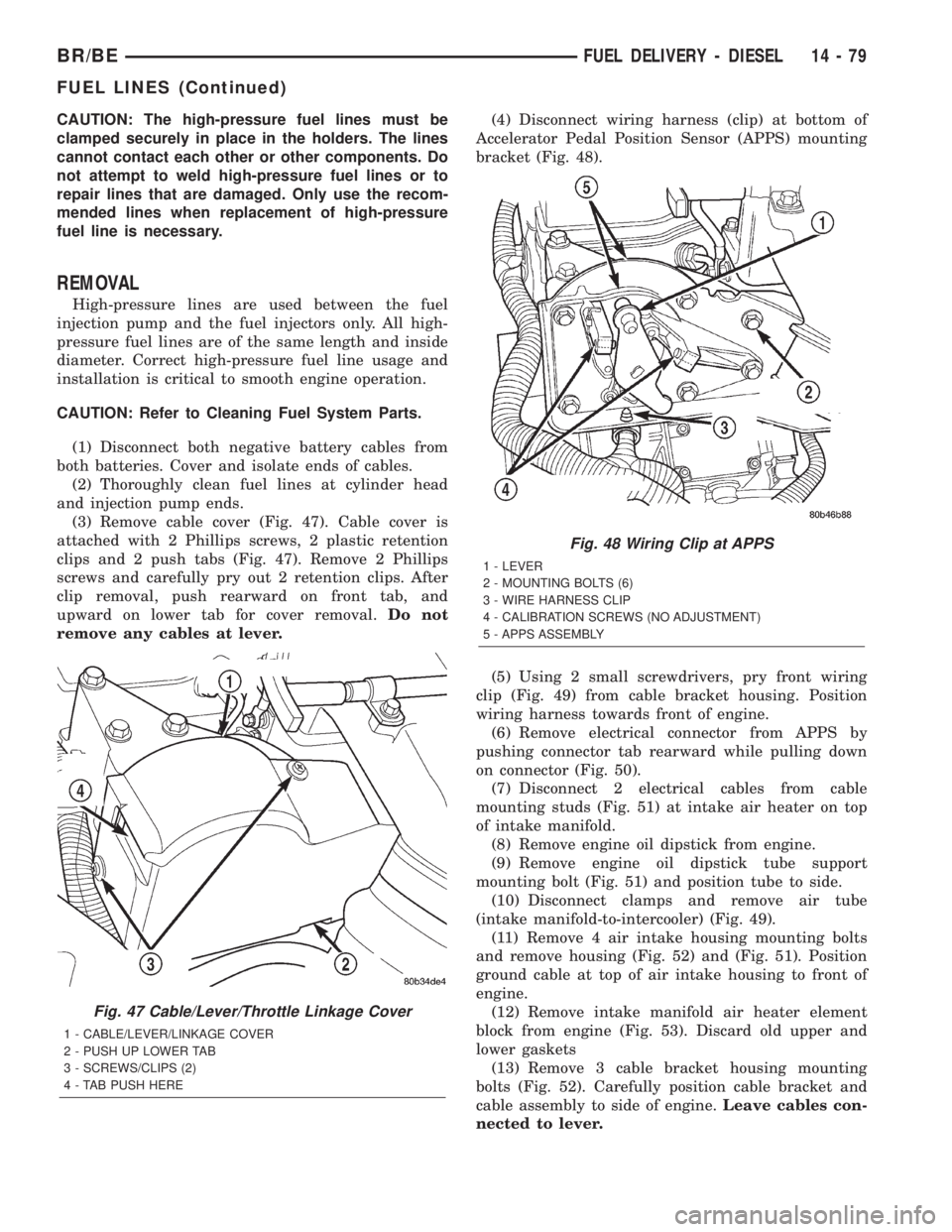
(3) Remove cable cover (Fig. 47). Cable cover is
attached with 2 Phillips screws, 2 plastic retention
clips and 2 push tabs (Fig. 47). Remove 2 Phillips
screws and carefully pry out 2 retention clips. After
clip removal, push rearward on front tab, and
upward on lower tab for cover removal.Do not
remove any cables at lever.(4) Disconnect wiring harness (clip) at bottom of
Accelerator Pedal Position Sensor (APPS) mounting
bracket (Fig. 48).
(5) Using 2 small screwdrivers, pry front wiring
clip (Fig. 49) from cable bracket housing. Position
wiring harness towards front of engine.
(6) Remove electrical connector from APPS by
pushing connector tab rearward while pulling down
on connector (Fig. 50).
(7) Disconnect 2 electrical cables from cable
mounting studs (Fig. 51) at intake air heater on top
of intake manifold.
(8) Remove engine oil dipstick from engine.
(9) Remove engine oil dipstick tube support
mounting bolt (Fig. 51) and position tube to side.
(10) Disconnect clamps and remove air tube
(intake manifold-to-intercooler) (Fig. 49).
(11) Remove 4 air intake housing mounting bolts
and remove housing (Fig. 52) and (Fig. 51). Position
ground cable at top of air intake housing to front of
engine.
(12) Remove intake manifold air heater element
block from engine (Fig. 53). Discard old upper and
lower gaskets
(13) Remove 3 cable bracket housing mounting
bolts (Fig. 52). Carefully position cable bracket and
cable assembly to side of engine.Leave cables con-
nected to lever.
Fig. 47 Cable/Lever/Throttle Linkage Cover
1 - CABLE/LEVER/LINKAGE COVER
2 - PUSH UP LOWER TAB
3 - SCREWS/CLIPS (2)
4 - TAB PUSH HERE
Fig. 48 Wiring Clip at APPS
1 - LEVER
2 - MOUNTING BOLTS (6)
3 - WIRE HARNESS CLIP
4 - CALIBRATION SCREWS (NO ADJUSTMENT)
5 - APPS ASSEMBLY
BR/BEFUEL DELIVERY - DIESEL 14 - 79
FUEL LINES (Continued)