2002 DODGE RAM battery
[x] Cancel search: batteryPage 1323 of 2255
QUICK CONNECT FITTING
DESCRIPTION
Different types of quick-connect fittings are used to
attach various fuel system components, lines and
tubes. These are: a single-tab type, a two-tab type or
a plastic retainer ring type. Some are equipped with
safety latch clips. Some may require the use of a spe-
cial tool for disconnection and removal. Refer to
Quick-Connect Fittings Removal/Installation for more
information.
CAUTION: The interior components (o-rings, clips)
of quick-connect fittings are not serviced sepa-
rately, but new plastic spacers are available for
some types. If service parts are not available, do
not attempt to repair the damaged fitting or fuel line
(tube). If repair is necessary, replace the complete
fuel line (tube) assembly.
STANDARD PROCEDURE - QUICK-CONNECT
FITTINGS
Also refer to Fuel Tubes/Lines/Hoses and Clamps.
Different types of quick-connect fittings are used to
attach various fuel system components, lines and
tubes. These are: a single-tab type, a two-tab type or
a plastic retainer ring type. Safety latch clips are
used on certain components/lines. Certain fittings
may require use of a special tool for disconnection.
DISCONNECTING
WARNING: THE FUEL SYSTEM IS UNDER A CON-
STANT PRESSURE (EVEN WITH ENGINE OFF).
BEFORE SERVICING ANY FUEL SYSTEM HOSE,
FITTING OR LINE, FUEL SYSTEM PRESSURE MUST
BE RELEASED. REFER TO FUEL SYSTEM PRES-
SURE RELEASE PROCEDURE.
CAUTION: The interior components (o-rings, spac-
ers) of some types of quick-connect fitting are not
serviced separately. If service parts are not avail-
able, do not attempt to repair a damaged fitting or
fuel line. If repair is necessary, replace complete
fuel line assembly.(1) Perform fuel pressure release procedure. Refer
to Fuel Pressure Release Procedure.
(2) Disconnect negative battery cable from battery.
(3) Clean fitting of any foreign material before dis-
assembly.
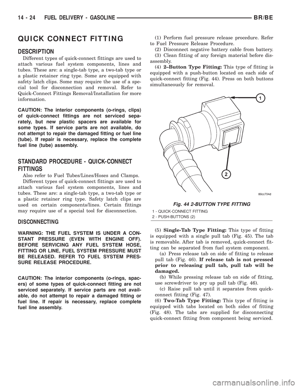
(4)2±Button Type Fitting:This type of fitting is
equipped with a push-button located on each side of
quick-connect fitting (Fig. 44). Press on both buttons
simultaneously for removal.
(5)Single-Tab Type Fitting:This type of fitting
is equipped with a single pull tab (Fig. 45). The tab
is removable. After tab is removed, quick-connect fit-
ting can be separated from fuel system component.
(a) Press release tab on side of fitting to release
pull tab (Fig. 46).If release tab is not pressed
prior to releasing pull tab, pull tab will be
damaged.
(b) While pressing release tab on side of fitting,
use screwdriver to pry up pull tab (Fig. 46).
(c) Raise pull tab until it separates from quick-
connect fitting (Fig. 47).
(6)Two-Tab Type Fitting:This type of fitting is
equipped with tabs located on both sides of fitting
(Fig. 48). The tabs are supplied for disconnecting
quick-connect fitting from component being serviced.
Fig. 44 2-BUTTON TYPE FITTING
1 - QUICK-CONNECT FITTING
2 - PUSH-BUTTONS (2)
14 - 24 FUEL DELIVERY - GASOLINEBR/BE
Page 1326 of 2255
(8)Latch Clips:Depending on vehicle model and
engine, 2 different types of safety latch clips are used
(Fig. 50) or (Fig. 51). Type-1 is tethered to fuel line
and type-2 is not. A special tool will be necessary to
disconnect fuel line after latch clip is removed. The
latch clip may be used on certain fuel line/fuel rail
connection, or to join fuel lines together.
(a) Type 1: Pry up on latch clip with a screw-
driver (Fig. 50).
(b) Type 2: Separate and unlatch 2 small arms
on end of clip (Fig. 51) and swing away from fuel
line.
(c) Slide latch clip toward fuel rail while lifting
with screwdriver.
(d) Insert special fuel line removal tool (Snap-On
number FIH 9055-1 or equivalent) into fuel line
(Fig. 52). Use tool to release locking fingers in end
of line.
(e) With special tool still inserted, pull fuel line
from fuel rail.
(f) After disconnection, locking fingers will
remain within quick-connect fitting at end of fuel
line.
(9) Disconnect quick-connect fitting from fuel sys-
tem component being serviced.CONNECTING
(1) Inspect quick-connect fitting body and fuel sys-
tem component for damage. Replace as necessary.
(2) Prior to connecting quick-connect fitting to
component being serviced, check condition of fitting
and component. Clean parts with a lint-free cloth.
Lubricate with clean engine oil.
(3) Insert quick-connect fitting into fuel tube or
fuel system component until built-on stop on fuel
tube or component rests against back of fitting.
(4) Continue pushing until a click is felt.
(5) Single-tab type fitting: Push new tab down
until it locks into place in quick-connect fitting.
(6) Verify a locked condition by firmly pulling on
fuel tube and fitting (15-30 lbs.).
(7) Latch Clip Equipped: Install latch clip (snaps
into position).If latch clip will not fit, this indi-
cates fuel line is not properly installed to fuel
rail (or other fuel line). Recheck fuel line con-
nection.
(8) Connect negative cable to battery.
(9) Start engine and check for leaks.
BR/BEFUEL DELIVERY - GASOLINE 14 - 27
QUICK CONNECT FITTING (Continued)
Page 1328 of 2255
FUEL INJECTION - GASOLINE
DIAGNOSIS AND TESTING
VISUAL INSPECTIONÐ5.9L ENGINES
A visual inspection for loose, disconnected or incor-
rectly routed wires and hoses should be made. This
should be done before attempting to diagnose or ser-
vice the fuel injection system. A visual check will
help spot these faults and save unnecessary test and
diagnostic time. A thorough visual inspection will
include the following checks:
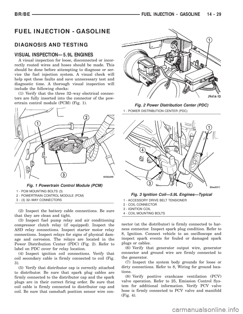
(1) Verify that the three 32±way electrical connec-
tors are fully inserted into the connector of the pow-
ertrain control module (PCM) (Fig. 1).
(2) Inspect the battery cable connections. Be sure
that they are clean and tight.
(3) Inspect fuel pump relay and air conditioning
compressor clutch relay (if equipped). Inspect the
ASD relay connections. Inspect starter motor relay
connections. Inspect relays for signs of physical dam-
age and corrosion. The relays are located in the
Power Distribution Center (PDC) (Fig. 2). Refer to
label on PDC cover for relay location.
(4) Inspect ignition coil connections. Verify that
coil secondary cable is firmly connected to coil (Fig.
3).
(5) Verify that distributor cap is correctly attached
to distributor. Be sure that spark plug cables are
firmly connected to the distributor cap and the spark
plugs are in their correct firing order. Be sure that
coil cable is firmly connected to distributor cap and
coil. Be sure that camshaft position sensor wire con-nector (at the distributor) is firmly connected to har-
ness connector. Inspect spark plug condition. Refer to
8, Ignition. Connect vehicle to an oscilloscope and
inspect spark events for fouled or damaged spark
plugs or cables.
(6) Verify that generator output wire, generator
connector and ground wire are firmly connected to
the generator.
(7) Inspect the system body grounds for loose or
dirty connections. Refer to 8, Wiring for ground loca-
tions.
(8) Verify positive crankcase ventilation (PCV)
valve operation. Refer to 25, Emission Control Sys-
tem for additional information. Verify PCV valve
hose is firmly connected to PCV valve and manifold
(Fig. 4).
Fig. 1 Powertrain Control Module (PCM)
1 - PCM MOUNTING BOLTS (3)
2 - POWERTRAIN CONTROL MODULE (PCM)
3 - (3) 32±WAY CONNECTORS
Fig. 2 Power Distribution Center (PDC)
1 - POWER DISTRIBUTION CENTER (PDC)
Fig. 3 Ignition CoilÐ5.9L EnginesÐTypical
1 - ACCESSORY DRIVE BELT TENSIONER
2 - COIL CONNECTOR
3 - IGNITION COIL
4 - COIL MOUNTING BOLTS
BR/BEFUEL INJECTION - GASOLINE 14 - 29
Page 1331 of 2255
(29) Inspect transmission torque convertor housing
(automatic transmission) or clutch housing (manual
transmission) for damage to timing ring on drive
plate/flywheel.
(30) Verify that battery cable and solenoid feed
wire connections to the starter solenoid are tight and
clean. Inspect for chaffed wires or wires rubbing up
against other components.
VISUAL INSPECTIONÐ8.0L ENGINE
A visual inspection for loose, disconnected or incor-
rectly routed wires and hoses should be made. This
should be done before attempting to diagnose or ser-
vice the fuel injection system. A visual check will
help spot these faults and save unnecessary test and
diagnostic time. A thorough visual inspection will
include the following checks:
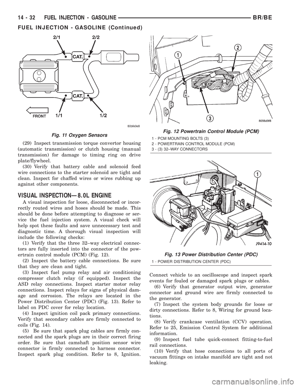
(1) Verify that the three 32±way electrical connec-
tors are fully inserted into the connector of the pow-
ertrain control module (PCM) (Fig. 12).
(2) Inspect the battery cable connections. Be sure
that they are clean and tight.
(3) Inspect fuel pump relay and air conditioning
compressor clutch relay (if equipped). Inspect the
ASD relay connections. Inspect starter motor relay
connections. Inspect relays for signs of physical dam-
age and corrosion. The relays are located in the
Power Distribution Center (PDC) (Fig. 13). Refer to
label on PDC cover for relay location.
(4) Inspect ignition coil pack primary connections.
Verify that secondary cables are firmly connected to
coils (Fig. 14).
(5) Be sure that spark plug cables are firmly con-
nected and the spark plugs are in their correct firing
order. Be sure that camshaft position sensor wire
connector is firmly connected to harness connector.
Inspect spark plug condition. Refer to 8, Ignition.Connect vehicle to an oscilloscope and inspect spark
events for fouled or damaged spark plugs or cables.
(6) Verify that generator output wire, generator
connector and ground wire are firmly connected to
the generator.
(7) Inspect the system body grounds for loose or
dirty connections. Refer to 8, Wiring for ground loca-
tions.
(8) Verify crankcase ventilation (CCV) operation.
Refer to 25, Emission Control System for additional
information.
(9) Inspect fuel tube quick-connect fitting-to-fuel
rail connections.
(10) Verify that hose connections to all ports of
vacuum fittings on intake manifold are tight and not
leaking.
Fig. 11 Oxygen SensorsFig. 12 Powertrain Control Module (PCM)
1 - PCM MOUNTING BOLTS (3)
2 - POWERTRAIN CONTROL MODULE (PCM)
3 - (3) 32±WAY CONNECTORS
Fig. 13 Power Distribution Center (PDC)
1 - POWER DISTRIBUTION CENTER (PDC)
14 - 32 FUEL INJECTION - GASOLINEBR/BE
FUEL INJECTION - GASOLINE (Continued)
Page 1333 of 2255
(20) Raise and support the vehicle.
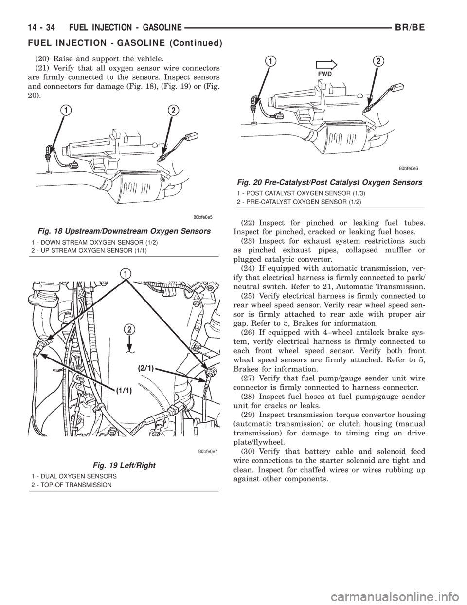
(21) Verify that all oxygen sensor wire connectors
are firmly connected to the sensors. Inspect sensors
and connectors for damage (Fig. 18), (Fig. 19) or (Fig.
20).
(22) Inspect for pinched or leaking fuel tubes.
Inspect for pinched, cracked or leaking fuel hoses.
(23) Inspect for exhaust system restrictions such
as pinched exhaust pipes, collapsed muffler or
plugged catalytic convertor.
(24) If equipped with automatic transmission, ver-
ify that electrical harness is firmly connected to park/
neutral switch. Refer to 21, Automatic Transmission.
(25) Verify electrical harness is firmly connected to
rear wheel speed sensor. Verify rear wheel speed sen-
sor is firmly attached to rear axle with proper air
gap. Refer to 5, Brakes for information.
(26) If equipped with 4±wheel antilock brake sys-
tem, verify electrical harness is firmly connected to
each front wheel speed sensor. Verify both front
wheel speed sensors are firmly attached. Refer to 5,
Brakes for information.
(27) Verify that fuel pump/gauge sender unit wire
connector is firmly connected to harness connector.
(28) Inspect fuel hoses at fuel pump/gauge sender
unit for cracks or leaks.
(29) Inspect transmission torque convertor housing
(automatic transmission) or clutch housing (manual
transmission) for damage to timing ring on drive
plate/flywheel.
(30) Verify that battery cable and solenoid feed
wire connections to the starter solenoid are tight and
clean. Inspect for chaffed wires or wires rubbing up
against other components.
Fig. 18 Upstream/Downstream Oxygen Sensors
1 - DOWN STREAM OXYGEN SENSOR (1/2)
2 - UP STREAM OXYGEN SENSOR (1/1)
Fig. 19 Left/Right
1 - DUAL OXYGEN SENSORS
2 - TOP OF TRANSMISSION
Fig. 20 Pre-Catalyst/Post Catalyst Oxygen Sensors
1 - POST CATALYST OXYGEN SENSOR (1/3)
2 - PRE-CATALYST OXYGEN SENSOR (1/2)
14 - 34 FUEL INJECTION - GASOLINEBR/BE
FUEL INJECTION - GASOLINE (Continued)
Page 1339 of 2255
CAUTION: Before tightening sensor mounting bolt,
be sure sensor is completely flush to cylinder block
(Fig. 28). If sensor is not flush, damage to sensor
mounting tang may result.
(3) Install mounting bolt and tighten to 8 N´m (70
in. lbs.) torque.
(4) Connect sensor pigtail harness to main engine
wiring harness
(5) Install new plastic tie strap (Fig. 27) to secure
sensor pigtail harness to side of engine block. Thread
tie strap through casting hole on cylinder block.
FUEL PUMP RELAY
DESCRIPTION
The 5±pin, 12±volt, fuel pump relay is located in
the Power Distribution Center (PDC). Refer to the
label on the PDC cover for relay location.
OPERATION
The Powertrain Control Module (PCM) energizes
the electric fuel pump through the fuel pump relay.
The fuel pump relay is energized by first applying
battery voltage to it when the ignition key is turned
ON, and then applying a ground signal to the relay
from the PCM.
Whenever the ignition key is turned ON, the elec-
tric fuel pump will operate. But, the PCM will shut-
down the ground circuit to the fuel pump relay in
approximately 1±3 seconds unless the engine is oper-
ating or the starter motor is engaged.
REMOVAL
The fuel pump relay is located in the Power Distri-
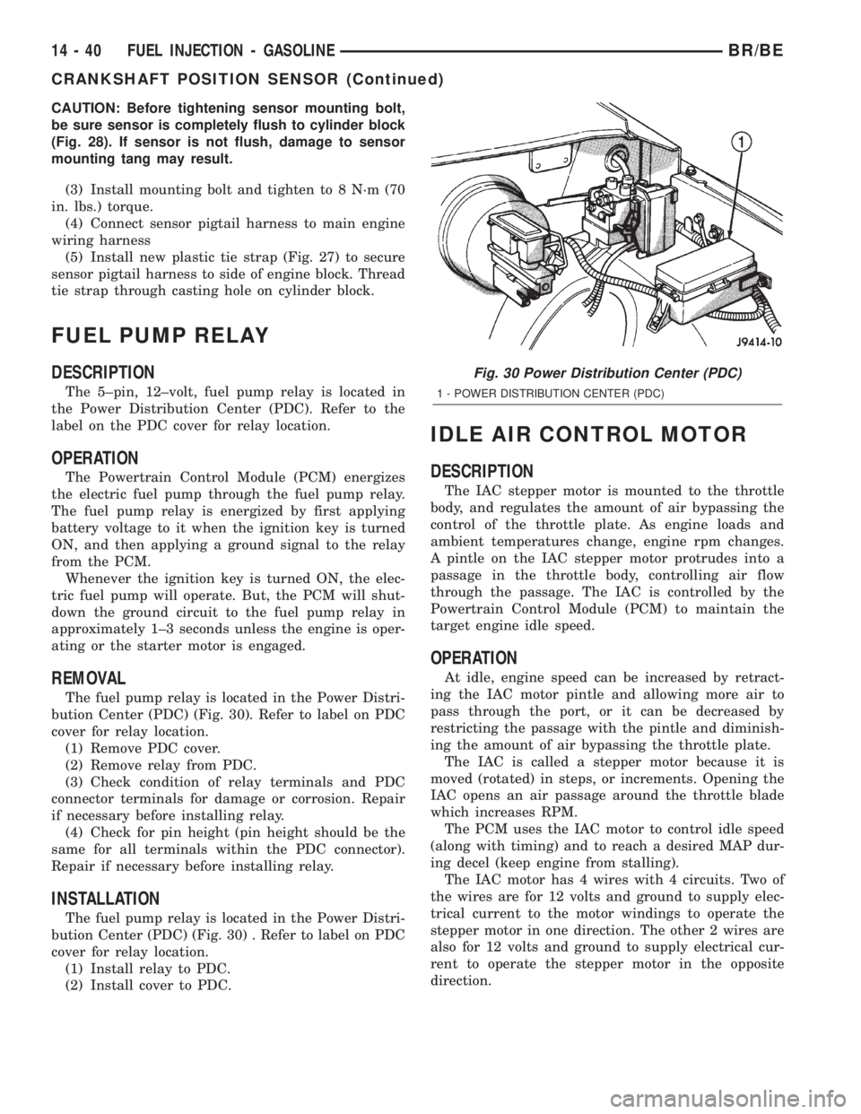
bution Center (PDC) (Fig. 30). Refer to label on PDC
cover for relay location.
(1) Remove PDC cover.
(2) Remove relay from PDC.
(3) Check condition of relay terminals and PDC
connector terminals for damage or corrosion. Repair
if necessary before installing relay.
(4) Check for pin height (pin height should be the
same for all terminals within the PDC connector).
Repair if necessary before installing relay.
INSTALLATION
The fuel pump relay is located in the Power Distri-
bution Center (PDC) (Fig. 30) . Refer to label on PDC
cover for relay location.
(1) Install relay to PDC.
(2) Install cover to PDC.
IDLE AIR CONTROL MOTOR
DESCRIPTION
The IAC stepper motor is mounted to the throttle
body, and regulates the amount of air bypassing the
control of the throttle plate. As engine loads and
ambient temperatures change, engine rpm changes.
A pintle on the IAC stepper motor protrudes into a
passage in the throttle body, controlling air flow
through the passage. The IAC is controlled by the
Powertrain Control Module (PCM) to maintain the
target engine idle speed.
OPERATION
At idle, engine speed can be increased by retract-
ing the IAC motor pintle and allowing more air to
pass through the port, or it can be decreased by
restricting the passage with the pintle and diminish-
ing the amount of air bypassing the throttle plate.
The IAC is called a stepper motor because it is
moved (rotated) in steps, or increments. Opening the
IAC opens an air passage around the throttle blade
which increases RPM.
The PCM uses the IAC motor to control idle speed
(along with timing) and to reach a desired MAP dur-
ing decel (keep engine from stalling).
The IAC motor has 4 wires with 4 circuits. Two of
the wires are for 12 volts and ground to supply elec-
trical current to the motor windings to operate the
stepper motor in one direction. The other 2 wires are
also for 12 volts and ground to supply electrical cur-
rent to operate the stepper motor in the opposite
direction.
Fig. 30 Power Distribution Center (PDC)
1 - POWER DISTRIBUTION CENTER (PDC)
14 - 40 FUEL INJECTION - GASOLINEBR/BE
CRANKSHAFT POSITION SENSOR (Continued)
Page 1344 of 2255
(2) Clean the area around the sensor before
removal.
(3) Remove the two sensor mounting bolts.
(4) Remove the sensor from the intake manifold.
INSTALLATION
INSTALLATION - 5.9L
The MAP sensor is located on the front of the
throttle body (Fig. 35). An L-shaped rubber fitting is
used to connect the MAP sensor to throttle body (Fig.
36).
(1) Install rubber L-shaped fitting to MAP sensor.
(2) Position sensor to throttle body while guiding
rubber fitting over throttle body vacuum nipple.
(3) Install MAP sensor mounting bolts (screws).
Tighten screws to 3 N´m (25 in. lbs.) torque.
(4) Install air cleaner.
INSTALLATION - 8.0L
The MAP sensor is mounted into the right upper
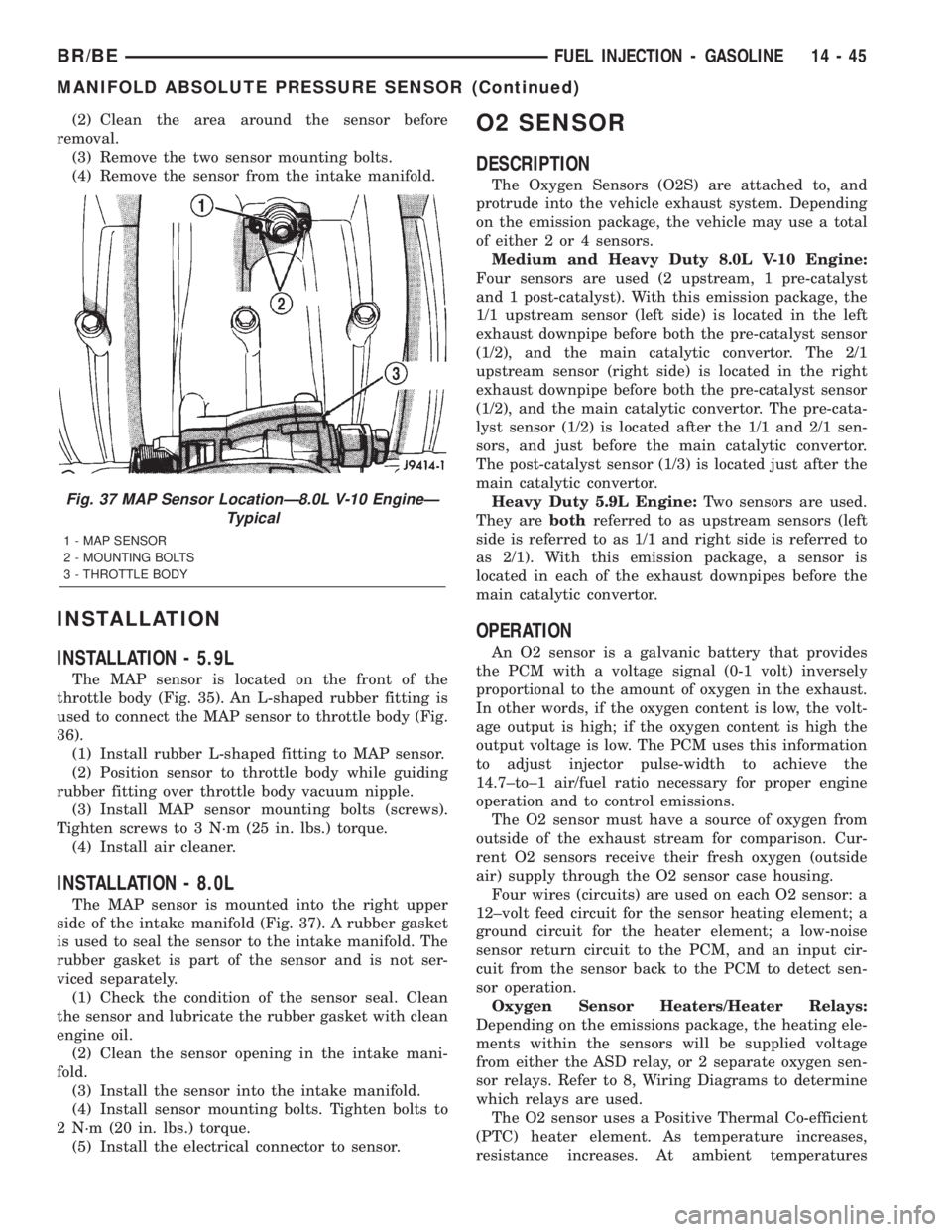
side of the intake manifold (Fig. 37). A rubber gasket
is used to seal the sensor to the intake manifold. The
rubber gasket is part of the sensor and is not ser-
viced separately.
(1) Check the condition of the sensor seal. Clean
the sensor and lubricate the rubber gasket with clean
engine oil.
(2) Clean the sensor opening in the intake mani-
fold.
(3) Install the sensor into the intake manifold.
(4) Install sensor mounting bolts. Tighten bolts to
2 N´m (20 in. lbs.) torque.
(5) Install the electrical connector to sensor.
O2 SENSOR
DESCRIPTION
The Oxygen Sensors (O2S) are attached to, and
protrude into the vehicle exhaust system. Depending
on the emission package, the vehicle may use a total
of either 2 or 4 sensors.
Medium and Heavy Duty 8.0L V-10 Engine:
Four sensors are used (2 upstream, 1 pre-catalyst
and 1 post-catalyst). With this emission package, the
1/1 upstream sensor (left side) is located in the left
exhaust downpipe before both the pre-catalyst sensor
(1/2), and the main catalytic convertor. The 2/1
upstream sensor (right side) is located in the right
exhaust downpipe before both the pre-catalyst sensor
(1/2), and the main catalytic convertor. The pre-cata-
lyst sensor (1/2) is located after the 1/1 and 2/1 sen-
sors, and just before the main catalytic convertor.
The post-catalyst sensor (1/3) is located just after the
main catalytic convertor.
Heavy Duty 5.9L Engine:Two sensors are used.
They arebothreferred to as upstream sensors (left
side is referred to as 1/1 and right side is referred to
as 2/1). With this emission package, a sensor is
located in each of the exhaust downpipes before the
main catalytic convertor.
OPERATION
An O2 sensor is a galvanic battery that provides
the PCM with a voltage signal (0-1 volt) inversely
proportional to the amount of oxygen in the exhaust.
In other words, if the oxygen content is low, the volt-
age output is high; if the oxygen content is high the
output voltage is low. The PCM uses this information
to adjust injector pulse-width to achieve the
14.7±to±1 air/fuel ratio necessary for proper engine
operation and to control emissions.
The O2 sensor must have a source of oxygen from
outside of the exhaust stream for comparison. Cur-
rent O2 sensors receive their fresh oxygen (outside
air) supply through the O2 sensor case housing.
Four wires (circuits) are used on each O2 sensor: a
12±volt feed circuit for the sensor heating element; a
ground circuit for the heater element; a low-noise
sensor return circuit to the PCM, and an input cir-
cuit from the sensor back to the PCM to detect sen-
sor operation.
Oxygen Sensor Heaters/Heater Relays:
Depending on the emissions package, the heating ele-
ments within the sensors will be supplied voltage
from either the ASD relay, or 2 separate oxygen sen-
sor relays. Refer to 8, Wiring Diagrams to determine
which relays are used.
The O2 sensor uses a Positive Thermal Co-efficient
(PTC) heater element. As temperature increases,
resistance increases. At ambient temperatures
Fig. 37 MAP Sensor LocationÐ8.0L V-10 EngineÐ
Typical
1 - MAP SENSOR
2 - MOUNTING BOLTS
3 - THROTTLE BODY
BR/BEFUEL INJECTION - GASOLINE 14 - 45
MANIFOLD ABSOLUTE PRESSURE SENSOR (Continued)
Page 1351 of 2255
(2) Tighten bolts to 7 N´m (60 in. lbs.) torque.
(3) Manually operate the throttle control lever by
hand to check for any binding of the TPS.
(4) Connect TPS electrical connector to TPS.
(5) Install air cleaner housing to throttle body.
(6) Install 4 air cleaner housing mounting nuts.
Tighten nuts to 11 N´m (96 in. lbs.) torque.
(7) Install air cleaner housing cover.
(8) Install air intake tube to cover.
FUEL INJECTOR
DESCRIPTION
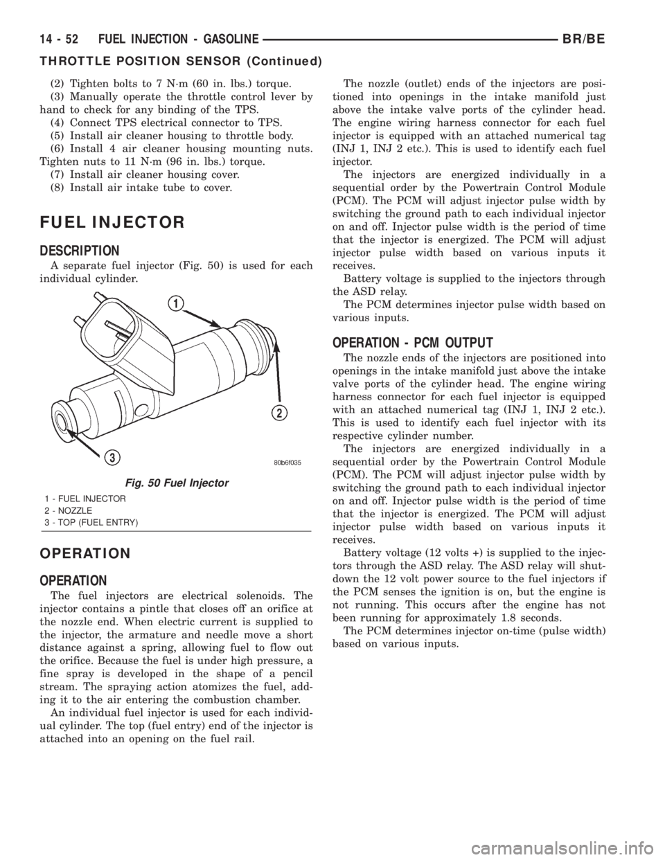
A separate fuel injector (Fig. 50) is used for each
individual cylinder.
OPERATION
OPERATION
The fuel injectors are electrical solenoids. The
injector contains a pintle that closes off an orifice at
the nozzle end. When electric current is supplied to
the injector, the armature and needle move a short
distance against a spring, allowing fuel to flow out
the orifice. Because the fuel is under high pressure, a
fine spray is developed in the shape of a pencil
stream. The spraying action atomizes the fuel, add-
ing it to the air entering the combustion chamber.
An individual fuel injector is used for each individ-
ual cylinder. The top (fuel entry) end of the injector is
attached into an opening on the fuel rail.The nozzle (outlet) ends of the injectors are posi-
tioned into openings in the intake manifold just
above the intake valve ports of the cylinder head.
The engine wiring harness connector for each fuel
injector is equipped with an attached numerical tag
(INJ 1, INJ 2 etc.). This is used to identify each fuel
injector.
The injectors are energized individually in a
sequential order by the Powertrain Control Module
(PCM). The PCM will adjust injector pulse width by
switching the ground path to each individual injector
on and off. Injector pulse width is the period of time
that the injector is energized. The PCM will adjust
injector pulse width based on various inputs it
receives.
Battery voltage is supplied to the injectors through
the ASD relay.
The PCM determines injector pulse width based on
various inputs.
OPERATION - PCM OUTPUT
The nozzle ends of the injectors are positioned into
openings in the intake manifold just above the intake
valve ports of the cylinder head. The engine wiring
harness connector for each fuel injector is equipped
with an attached numerical tag (INJ 1, INJ 2 etc.).
This is used to identify each fuel injector with its
respective cylinder number.
The injectors are energized individually in a
sequential order by the Powertrain Control Module
(PCM). The PCM will adjust injector pulse width by
switching the ground path to each individual injector
on and off. Injector pulse width is the period of time
that the injector is energized. The PCM will adjust
injector pulse width based on various inputs it
receives.
Battery voltage (12 volts +) is supplied to the injec-
tors through the ASD relay. The ASD relay will shut-
down the 12 volt power source to the fuel injectors if
the PCM senses the ignition is on, but the engine is
not running. This occurs after the engine has not
been running for approximately 1.8 seconds.
The PCM determines injector on-time (pulse width)
based on various inputs.
Fig. 50 Fuel Injector
1 - FUEL INJECTOR
2 - NOZZLE
3 - TOP (FUEL ENTRY)
14 - 52 FUEL INJECTION - GASOLINEBR/BE
THROTTLE POSITION SENSOR (Continued)