2002 DODGE RAM battery
[x] Cancel search: batteryPage 1404 of 2255
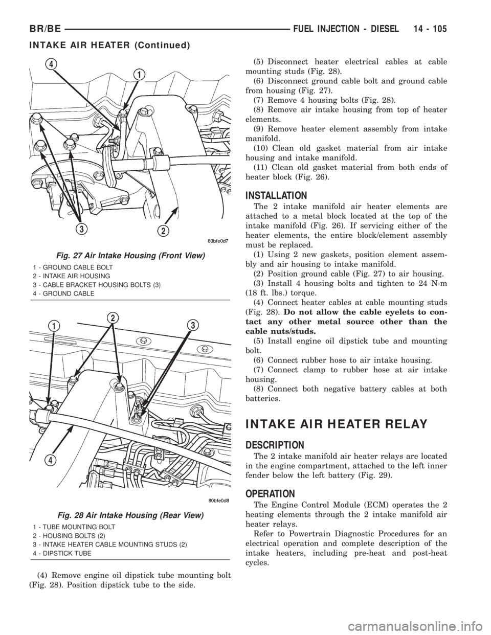
(4) Remove engine oil dipstick tube mounting bolt
(Fig. 28). Position dipstick tube to the side.(5) Disconnect heater electrical cables at cable
mounting studs (Fig. 28).
(6) Disconnect ground cable bolt and ground cable
from housing (Fig. 27).
(7) Remove 4 housing bolts (Fig. 28).
(8) Remove air intake housing from top of heater
elements.
(9) Remove heater element assembly from intake
manifold.
(10) Clean old gasket material from air intake
housing and intake manifold.
(11) Clean old gasket material from both ends of
heater block (Fig. 26).
INSTALLATION
The 2 intake manifold air heater elements are
attached to a metal block located at the top of the
intake manifold (Fig. 26). If servicing either of the
heater elements, the entire block/element assembly
must be replaced.
(1) Using 2 new gaskets, position element assem-
bly and air housing to intake manifold.
(2) Position ground cable (Fig. 27) to air housing.
(3) Install 4 housing bolts and tighten to 24 N´m
(18 ft. lbs.) torque.
(4) Connect heater cables at cable mounting studs
(Fig. 28).Do not allow the cable eyelets to con-
tact any other metal source other than the
cable nuts/studs.
(5) Install engine oil dipstick tube and mounting
bolt.
(6) Connect rubber hose to air intake housing.
(7) Connect clamp to rubber hose at air intake
housing.
(8) Connect both negative battery cables at both
batteries.
INTAKE AIR HEATER RELAY
DESCRIPTION
The 2 intake manifold air heater relays are located
in the engine compartment, attached to the left inner
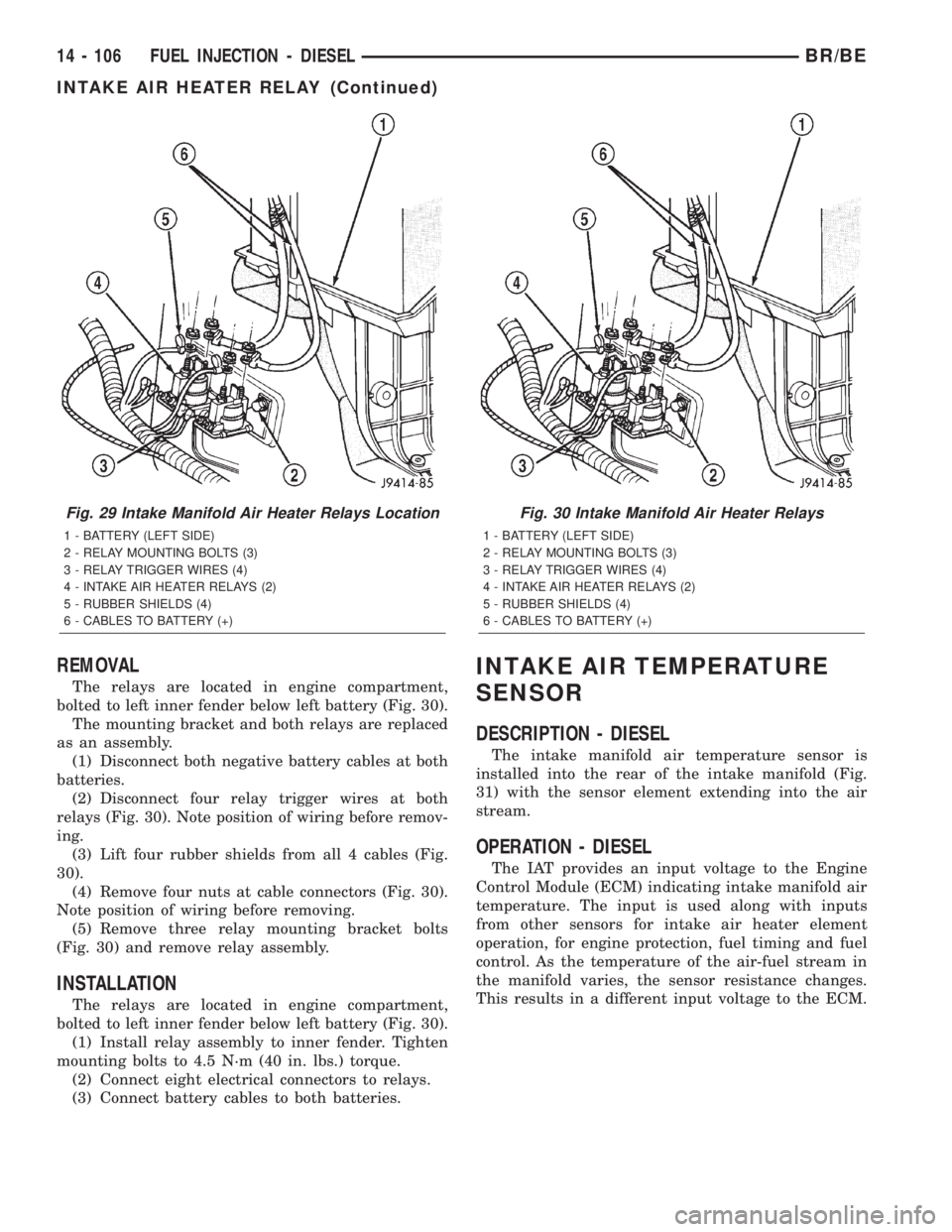
fender below the left battery (Fig. 29).
OPERATION
The Engine Control Module (ECM) operates the 2
heating elements through the 2 intake manifold air
heater relays.
Refer to Powertrain Diagnostic Procedures for an
electrical operation and complete description of the
intake heaters, including pre-heat and post-heat
cycles.
Fig. 27 Air Intake Housing (Front View)
1 - GROUND CABLE BOLT
2 - INTAKE AIR HOUSING
3 - CABLE BRACKET HOUSING BOLTS (3)
4 - GROUND CABLE
Fig. 28 Air Intake Housing (Rear View)
1 - TUBE MOUNTING BOLT
2 - HOUSING BOLTS (2)
3 - INTAKE HEATER CABLE MOUNTING STUDS (2)
4 - DIPSTICK TUBE
BR/BEFUEL INJECTION - DIESEL 14 - 105
INTAKE AIR HEATER (Continued)
Page 1405 of 2255
REMOVAL
The relays are located in engine compartment,
bolted to left inner fender below left battery (Fig. 30).
The mounting bracket and both relays are replaced
as an assembly.
(1) Disconnect both negative battery cables at both
batteries.
(2) Disconnect four relay trigger wires at both
relays (Fig. 30). Note position of wiring before remov-
ing.
(3) Lift four rubber shields from all 4 cables (Fig.
30).
(4) Remove four nuts at cable connectors (Fig. 30).
Note position of wiring before removing.
(5) Remove three relay mounting bracket bolts
(Fig. 30) and remove relay assembly.
INSTALLATION
The relays are located in engine compartment,
bolted to left inner fender below left battery (Fig. 30).
(1) Install relay assembly to inner fender. Tighten
mounting bolts to 4.5 N´m (40 in. lbs.) torque.
(2) Connect eight electrical connectors to relays.
(3) Connect battery cables to both batteries.
INTAKE AIR TEMPERATURE
SENSOR
DESCRIPTION - DIESEL
The intake manifold air temperature sensor is
installed into the rear of the intake manifold (Fig.
31) with the sensor element extending into the air
stream.
OPERATION - DIESEL
The IAT provides an input voltage to the Engine
Control Module (ECM) indicating intake manifold air
temperature. The input is used along with inputs
from other sensors for intake air heater element
operation, for engine protection, fuel timing and fuel
control. As the temperature of the air-fuel stream in
the manifold varies, the sensor resistance changes.
This results in a different input voltage to the ECM.
Fig. 29 Intake Manifold Air Heater Relays Location
1 - BATTERY (LEFT SIDE)
2 - RELAY MOUNTING BOLTS (3)
3 - RELAY TRIGGER WIRES (4)
4 - INTAKE AIR HEATER RELAYS (2)
5 - RUBBER SHIELDS (4)
6 - CABLES TO BATTERY (+)
Fig. 30 Intake Manifold Air Heater Relays
1 - BATTERY (LEFT SIDE)
2 - RELAY MOUNTING BOLTS (3)
3 - RELAY TRIGGER WIRES (4)
4 - INTAKE AIR HEATER RELAYS (2)
5 - RUBBER SHIELDS (4)
6 - CABLES TO BATTERY (+)
14 - 106 FUEL INJECTION - DIESELBR/BE
INTAKE AIR HEATER RELAY (Continued)
Page 1408 of 2255
THROTTLE CONTROL CABLE
REMOVAL
(1) Disconnect both negative battery cables at both
batteries.
(2) From inside vehicle, hold up accelerator pedal.
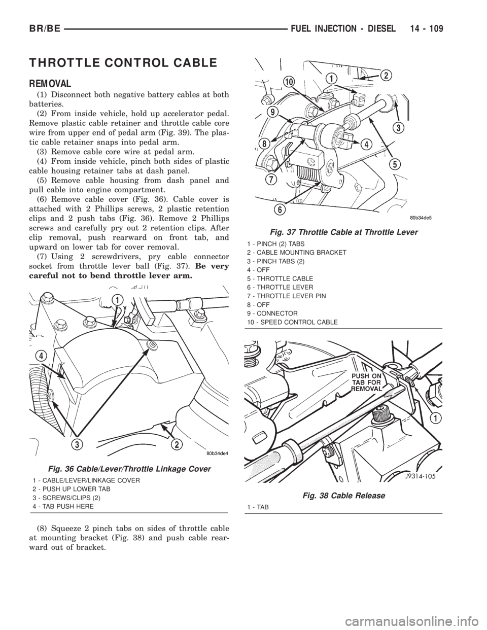
Remove plastic cable retainer and throttle cable core
wire from upper end of pedal arm (Fig. 39). The plas-
tic cable retainer snaps into pedal arm.
(3) Remove cable core wire at pedal arm.
(4) From inside vehicle, pinch both sides of plastic
cable housing retainer tabs at dash panel.
(5) Remove cable housing from dash panel and
pull cable into engine compartment.
(6) Remove cable cover (Fig. 36). Cable cover is
attached with 2 Phillips screws, 2 plastic retention
clips and 2 push tabs (Fig. 36). Remove 2 Phillips
screws and carefully pry out 2 retention clips. After
clip removal, push rearward on front tab, and
upward on lower tab for cover removal.
(7) Using 2 screwdrivers, pry cable connector
socket from throttle lever ball (Fig. 37).Be very
careful not to bend throttle lever arm.
(8) Squeeze 2 pinch tabs on sides of throttle cable
at mounting bracket (Fig. 38) and push cable rear-
ward out of bracket.
Fig. 36 Cable/Lever/Throttle Linkage Cover
1 - CABLE/LEVER/LINKAGE COVER
2 - PUSH UP LOWER TAB
3 - SCREWS/CLIPS (2)
4 - TAB PUSH HERE
Fig. 37 Throttle Cable at Throttle Lever
1 - PINCH (2) TABS
2 - CABLE MOUNTING BRACKET
3 - PINCH TABS (2)
4 - OFF
5 - THROTTLE CABLE
6 - THROTTLE LEVER
7 - THROTTLE LEVER PIN
8 - OFF
9 - CONNECTOR
10 - SPEED CONTROL CABLE
Fig. 38 Cable Release
1-TAB
BR/BEFUEL INJECTION - DIESEL 14 - 109
Page 1409 of 2255
INSTALLATION
(1) Install cable through mounting hole on cable
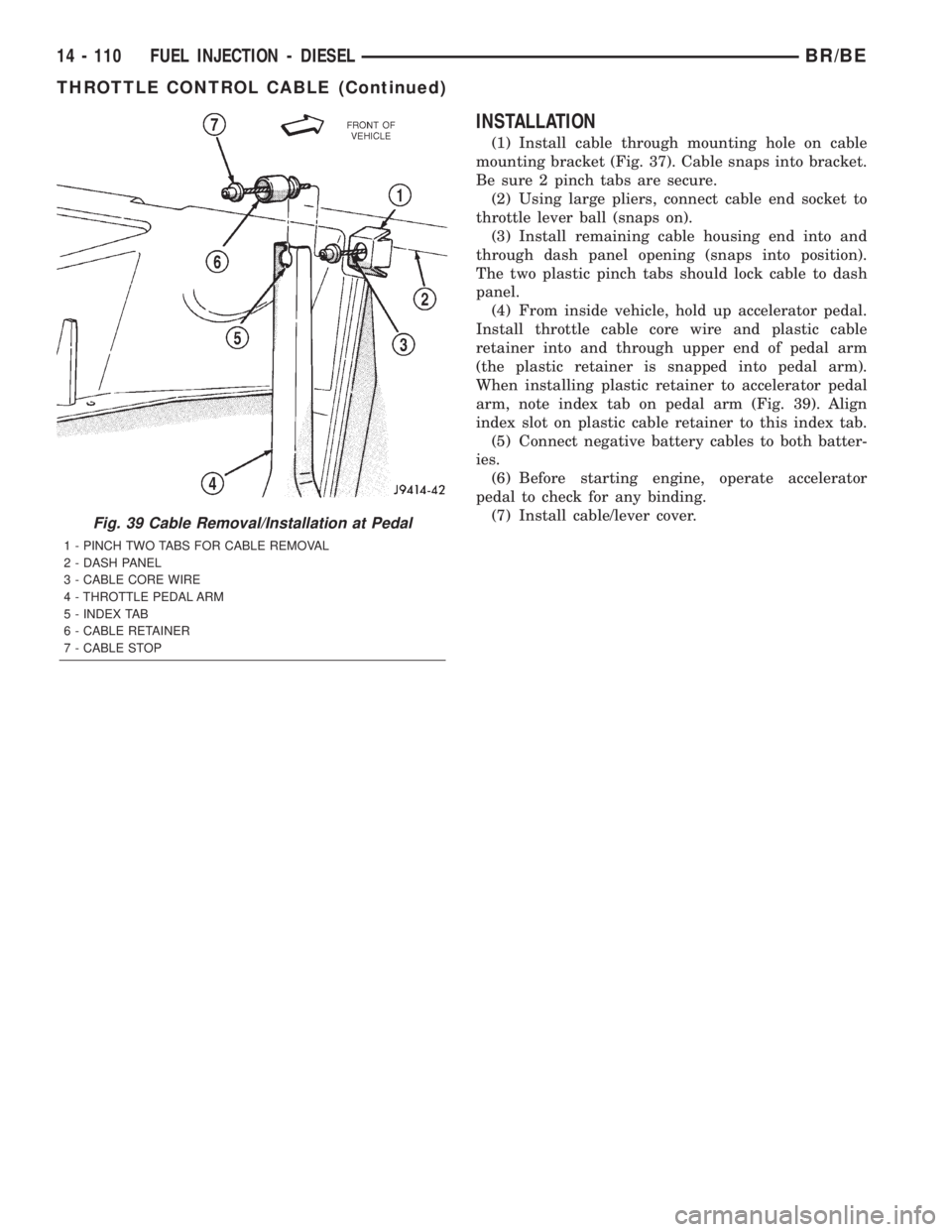
mounting bracket (Fig. 37). Cable snaps into bracket.
Be sure 2 pinch tabs are secure.
(2) Using large pliers, connect cable end socket to
throttle lever ball (snaps on).
(3) Install remaining cable housing end into and
through dash panel opening (snaps into position).
The two plastic pinch tabs should lock cable to dash
panel.
(4) From inside vehicle, hold up accelerator pedal.
Install throttle cable core wire and plastic cable
retainer into and through upper end of pedal arm
(the plastic retainer is snapped into pedal arm).
When installing plastic retainer to accelerator pedal
arm, note index tab on pedal arm (Fig. 39). Align
index slot on plastic cable retainer to this index tab.
(5) Connect negative battery cables to both batter-
ies.
(6) Before starting engine, operate accelerator
pedal to check for any binding.
(7) Install cable/lever cover.
Fig. 39 Cable Removal/Installation at Pedal
1 - PINCH TWO TABS FOR CABLE REMOVAL
2 - DASH PANEL
3 - CABLE CORE WIRE
4 - THROTTLE PEDAL ARM
5 - INDEX TAB
6 - CABLE RETAINER
7 - CABLE STOP
14 - 110 FUEL INJECTION - DIESELBR/BE
THROTTLE CONTROL CABLE (Continued)
Page 1415 of 2255
COLUMN
TABLE OF CONTENTS
page page
COLUMN
DESCRIPTION..........................6
OPERATION
SERVICE PRECAUTIONS................6
REMOVAL.............................6
INSTALLATION..........................8
SPECIFICATIONS
TORQUE CHART......................9
KEY-IN IGNITION SWITCH
DESCRIPTION..........................9
DIAGNOSIS AND TESTING - IGNITION
SWITCH AND KEY LOCK CYLINDER.......9
LOCK CYLINDER
REMOVAL.............................10INSTALLATION.........................10
IGNITION SWITCH
DESCRIPTION.........................11
OPERATION...........................11
DIAGNOSIS AND TESTING - IGNITION
SWITCH.............................11
REMOVAL.............................12
INSTALLATION.........................12
GEAR SHIFT LEVER
REMOVAL.............................14
INSTALLATION.........................15
STEERING WHEEL
REMOVAL.............................15
INSTALLATION.........................15
COLUMN
DESCRIPTION
The tilt and standard column (Fig. 1) has been
designed to be serviced as an assembly; less wiring,
switches, shrouds, steering wheel, etc. Most steering
column components can be serviced without remov-
ing the steering column from the vehicle.
OPERATION
SERVICE PRECAUTIONS
Safety goggles should be worn at all times when
working on steering columns.
To service the steering wheel, switches or the air-
bag, refer to the WARNINGS and CAUTIONS below.
WARNING: THE AIRBAG SYSTEM IS A SENSITIVE,
COMPLEX ELECTRO-MECHANICAL UNIT. BEFORE
ATTEMPTING TO DIAGNOSE, REMOVE OR INSTALL
THE AIRBAG SYSTEM COMPONENTS YOU MUST
FIRST DISCONNECT AND ISOLATE THE BATTERY
NEGATIVE (GROUND) CABLE. THEN WAIT TWO
MINUTES FOR THE SYSTEM CAPACITOR TO DIS-
CHARGE. FAILURE TO DO SO COULD RESULT IN
ACCIDENTAL DEPLOYMENT OF THE AIRBAG AND
POSSIBLE PERSONAL INJURY. THE FASTENERS,
SCREWS, AND BOLTS, ORIGINALLY USED FOR
THE AIRBAG COMPONENTS, HAVE SPECIAL COAT-INGS AND ARE SPECIFICALLY DESIGNED FOR THE
AIRBAG SYSTEM. THEY MUST NEVER BE
REPLACED WITH ANY SUBSTITUTES. ANYTIME A
NEW FASTENER IS NEEDED, REPLACE WITH THE
CORRECT FASTENERS PROVIDED IN THE SERVICE
PACKAGE OR FASTENERS LISTED IN THE PARTS
BOOKS.
CAUTION: Do not hammer on steering column shaft
or shift tube. This may cause the shaft/shift tube to
collapse or damage the bearing.
CAUTION: Do not attempt to remove the pivot pins
to disassemble the tilting mechanism. Do not
remove shaft lock plate, plate retainer, park lock
link or slider. This will damage the column (Fig. 2)
and (Fig. 3).
REMOVAL
(1) Position the front wheels straight ahead.
(2) Disconnect the negative (ground) cable from
the battery.
(3) Remove the airbag, (Refer to 8 - ELECTRICAL/
RESTRAINTS/DRIVER AIRBAG - REMOVAL).
(4) Remove the steering wheel with an appropriate
puller,(Refer to 19 - STEERING/COLUMN/STEER-
ING WHEEL - REMOVAL).
19 - 6 COLUMNBR/BE
Page 1418 of 2255
(3) Remove the shipping lock pin if necessary.
(4) Install the column through the floor pan.
(5) Position the column bracket breakaway cap-
sules on the mounting studs. Install, butloose
assemblethe two upper bracket nuts.
(6) With the front wheels in the straight-ahead
position. Align steering column shaft to the coupler.
Install anewpinch bolt and tighten to 49 N´m (36
ft. lbs.).
(7) Clip the wiring harness on the steering column.
Connect the multi- function switch wiring and
tighten with 7mm socket.
(8) Install the upper fixed shroud.
(9) Be sure both breakaway capsules are fully
seated in the slots in the column support bracket.
Pull the column rearward then tighten upper bracket
nuts to 12 N´m (105 in. lbs.).
(10) Tighten the toe plate to floor pan attaching
nuts to 22.5 N´m (200 in. lbs.).
(11) Install the wiring connections to the column.
Install the lower fixed shroud.
(12) Column shift vehicles, install the PRNDL
driver cable. Place shifter in Park position. If indica-tor needs adjusting, turn thumb screw on cable
retainer to adjust cable.
(13) Install the lock housing shrouds. Install the
tilt lever (if equipped).
(14) Install the knee blocker and steering column
opening cover, (Refer to 23 - BODY/INSTRUMENT
PANEL/STEERING COLUMN OPENING COVER -
INSTALLATION).
(15) Install steering wheel and tighten nut to 61
N´m (45 ft. lbs.), (Refer to 19 - STEERING/COL-
UMN/STEERING WHEEL - INSTALLATION).
(16) Install the airbag, (Refer to 8 - ELECTRICAL/
RESTRAINTS/DRIVER AIRBAG - INSTALLATION).
(17) Column shift vehicles, connect the shift link
rod to the transmission shift lever. Use multi-purpose
lubricant, or an equivalent product, to aid the instal-
lation.
(18) Install the battery ground (negative) cable.
(19) Verify operation of the automatic transmission
shift linkage and adjust as necessary, (Refer to 21 -
TRANSMISSION/TRANSAXLE/AUTOMATIC -
44RE/GEAR SHIFT CABLE - ADJUSTMENTS).
SPECIFICATIONS
TORQUE CHART
TORQUE SPECIFICATIONS
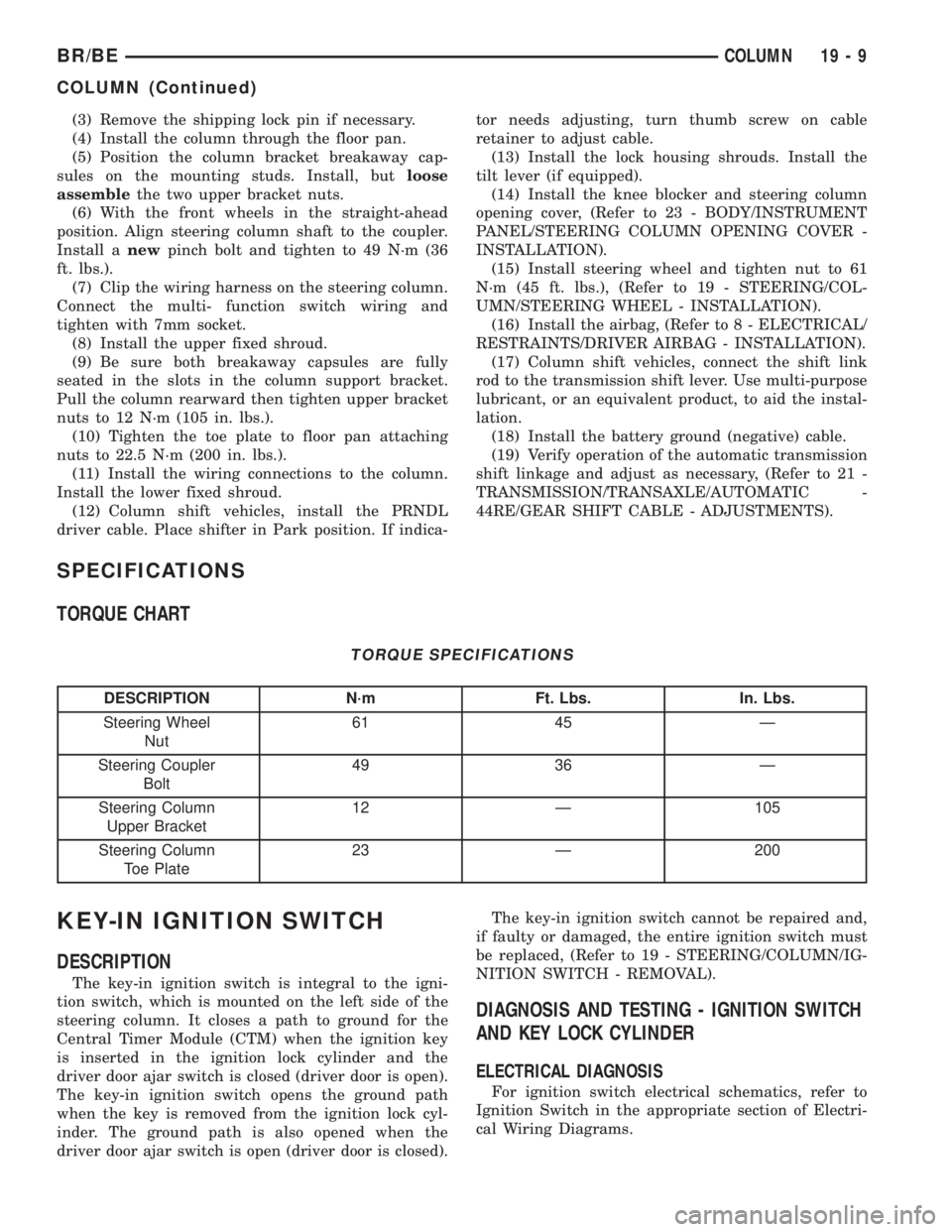
DESCRIPTION N´m Ft. Lbs. In. Lbs.
Steering Wheel
Nut61 45 Ð
Steering Coupler
Bolt49 36 Ð
Steering Column
Upper Bracket12 Ð 105
Steering Column
Toe Plate23 Ð 200
KEY-IN IGNITION SWITCH
DESCRIPTION
The key-in ignition switch is integral to the igni-
tion switch, which is mounted on the left side of the
steering column. It closes a path to ground for the
Central Timer Module (CTM) when the ignition key
is inserted in the ignition lock cylinder and the
driver door ajar switch is closed (driver door is open).
The key-in ignition switch opens the ground path
when the key is removed from the ignition lock cyl-
inder. The ground path is also opened when the
driver door ajar switch is open (driver door is closed).The key-in ignition switch cannot be repaired and,
if faulty or damaged, the entire ignition switch must
be replaced, (Refer to 19 - STEERING/COLUMN/IG-
NITION SWITCH - REMOVAL).
DIAGNOSIS AND TESTING - IGNITION SWITCH
AND KEY LOCK CYLINDER
ELECTRICAL DIAGNOSIS
For ignition switch electrical schematics, refer to
Ignition Switch in the appropriate section of Electri-
cal Wiring Diagrams.
BR/BECOLUMN 19 - 9
COLUMN (Continued)
Page 1419 of 2255
MECHANICAL DIAGNOSIS (KEY DIFFICULT TO
ROTATE)
Vehicles equipped with an automatic trans-
mission and a floor mounted shifter:a cable is
used to connect the interlock device in the steering
column assembly, to the transmission floor shift
lever. This interlock device is used to lock the trans-
mission shifter in the PARK position when the key
lock cylinder is rotated to the LOCKED or ACCES-
SORY position. The interlock device within the steer-
ing column is not serviceable. If repair is necessary,
the steering column assembly must be replaced.
(Refer to 19 - STEERING/COLUMN - REMOVAL).
If the ignition key is difficult to rotate to or from
the LOCK or ACCESSORY position, it may not be
the fault of the key cylinder or the steering column
components. The brake transmission shift interlock
cable may be out of adjustment. Refer to Brake
Transmission Shift Interlock Cable Adjustment in
Transmissions for adjustment procedures.
Vehicles equipped with an automatic trans-
mission and a steering column mounted shifter:
an interlock device is located within the steering col-
umn. This interlock device is used to lock the trans-
mission shifter in the PARK position when the key
lock cylinder is in the LOCKED or ACCESSORY
position. If it is difficult to rotate the key to or from
the LOCK or ACCESSORY position, the interlock
device within the steering column may be defective.
This device is not serviceable. If repair is necessary,
the steering column assembly must be replaced.
(Refer to 19 - STEERING/COLUMN - REMOVAL).
Vehicles equipped with a manual transmis-
sion and a floor mounted shifter:on certain mod-
els, a lever is located on the steering column behind
the ignition key lock cylinder. The lever must be
manually operated to allow rotation of the ignition
key lock cylinder to the LOCK or ACCESSORY posi-
tion. If it is difficult to rotate the key to the LOCK or
ACCESSORY position, the lever mechanism may be
defective. This mechanism is not serviceable. If
repair is necessary, the steering column assembly
must be replaced. (Refer to 19 - STEERING/COL-
UMN - REMOVAL).
On other models, the ignition key cylinder must be
depressed to allow it to be rotated into the LOCK or
ACCESSORY position. If it is difficult to rotate the
key to the LOCK or ACCESSORY position, the lock
mechanism within the steering column may be defec-
tive. This mechanism is not serviceable. If repair is
necessary, the steering column assembly must be
replaced. (Refer to 19 - STEERING/COLUMN -
REMOVAL).
LOCK CYLINDER
REMOVAL
The ignition key must be in the key cylinder for
cylinder removal.
(1) Disconnect negative cable from battery.
(2) If equipped with tilt column, remove tilt lever
by turning it counterclockwise.
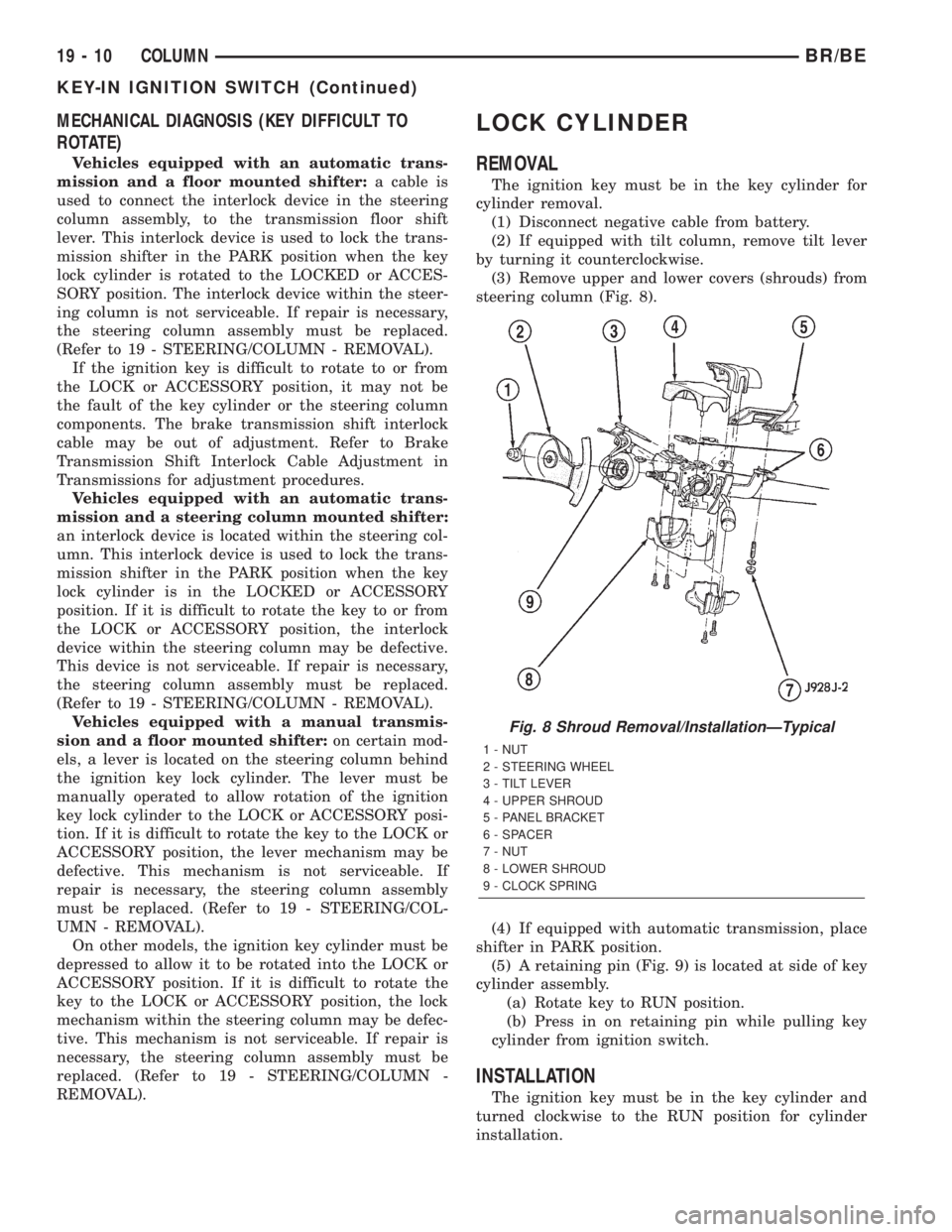
(3) Remove upper and lower covers (shrouds) from
steering column (Fig. 8).
(4) If equipped with automatic transmission, place
shifter in PARK position.
(5) A retaining pin (Fig. 9) is located at side of key
cylinder assembly.
(a) Rotate key to RUN position.
(b) Press in on retaining pin while pulling key
cylinder from ignition switch.
INSTALLATION
The ignition key must be in the key cylinder and
turned clockwise to the RUN position for cylinder
installation.
Fig. 8 Shroud Removal/InstallationÐTypical
1 - NUT
2 - STEERING WHEEL
3 - TILT LEVER
4 - UPPER SHROUD
5 - PANEL BRACKET
6 - SPACER
7 - NUT
8 - LOWER SHROUD
9 - CLOCK SPRING
19 - 10 COLUMNBR/BE
KEY-IN IGNITION SWITCH (Continued)
Page 1423 of 2255
(e) After installing the ignition switch rotate the
ignition key from the LOCK to the ON position.
Verify that the park lock slider moves in the slider
slot, allowing the gear shift lever to be moved out
of PARK (automatic transmissions only). If the
slider does not move , and the gear shift lever is
locked in PARK, the ignition switch park lock
dowel pin, on the rear of the ignition switch, is not
properly installed in the slot of the park lock slider
linkage. Remove the ignition switch and reinstall.
(11) Connect the electrical connectors for the igni-
tion switch and halo lamp.
(12) Install the steering column shrouds. Tighten
the screws to 2 N´m (17 in. lbs.).
(13) Install the tilt column lever. (if equipped).
(14) Connect the battery.
(15) Automatic Transmissions Only: The shifter
should lock in the PARK position when the key is in
the LOCK position (if equipped with a shift lock
device). The shifter should unlock when the key is
rotated to the ON position.
(16) Check for proper operation of the ignition
switch in ACCESSARY, LOCK, OFF, ON, RUN and
start positions.
(17) The steering wheel should lock when the key
is in the LOCK position. Rotate the steering wheel at
least 180É to verify. The steering wheel should unlock
when the key is rotated to the ON position.GEAR SHIFT LEVER
REMOVAL
(1) Remove the tilt lever.
(2) Remove the upper and lower shrouds.
(3) Remove the steering column opening cover
(Refer to 23 - BODY/INSTRUMENT PANEL/STEER-
ING COLUMN OPENING COVER - REMOVAL).
(4) Remove the steering column mounting nuts.
(5) Lower the steering column to remove the sec-
ondary shrouds.
(6) Raise the steering column back on the mount-
ing bolts and finger tighten the nuts.
(7) Disconnect over drive switch wiring.
(8) Using a drift of the appropriate size drive the
knurled pin out of the steering column and gear shift
lever. Remove the gear shift lever from the steering
column assembly.
CAUTION: The pin can only be removed from the
direction shown (Fig. 19).
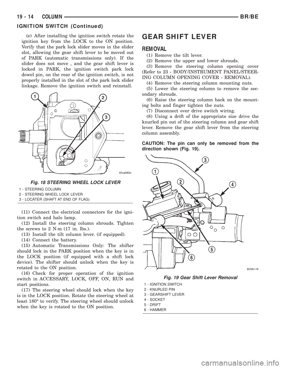
Fig. 18 STEERING WHEEL LOCK LEVER
1 - STEERING COLUMN
2 - STEERING WHEEL LOCK LEVER
3 - LOCATER (SHAFT AT END OF FLAG)
Fig. 19 Gear Shift Lever Removal
1 - IGNITION SWITCH
2 - KNURLED PIN
3 - GEARSHIFT LEVER
4 - SOCKET
5 - DRIFT
6 - HAMMER
19 - 14 COLUMNBR/BE
IGNITION SWITCH (Continued)