2002 DODGE RAM battery
[x] Cancel search: batteryPage 1256 of 2255
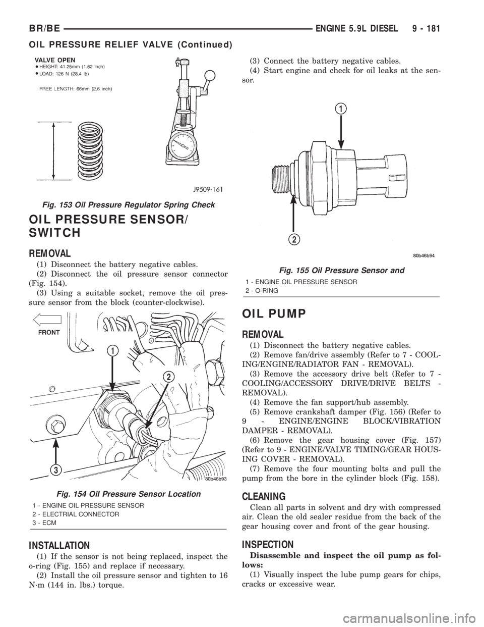
OIL PRESSURE SENSOR/
SWITCH
REMOVAL
(1) Disconnect the battery negative cables.
(2) Disconnect the oil pressure sensor connector
(Fig. 154).
(3) Using a suitable socket, remove the oil pres-
sure sensor from the block (counter-clockwise).
INSTALLATION
(1) If the sensor is not being replaced, inspect the
o-ring (Fig. 155) and replace if necessary.
(2) Install the oil pressure sensor and tighten to 16
N´m (144 in. lbs.) torque.(3) Connect the battery negative cables.
(4) Start engine and check for oil leaks at the sen-
sor.
OIL PUMP
REMOVAL
(1) Disconnect the battery negative cables.
(2) Remove fan/drive assembly (Refer to 7 - COOL-
ING/ENGINE/RADIATOR FAN - REMOVAL).
(3) Remove the accessory drive belt (Refer to 7 -
COOLING/ACCESSORY DRIVE/DRIVE BELTS -
REMOVAL).
(4) Remove the fan support/hub assembly.
(5) Remove crankshaft damper (Fig. 156) (Refer to
9 - ENGINE/ENGINE BLOCK/VIBRATION
DAMPER - REMOVAL).
(6) Remove the gear housing cover (Fig. 157)
(Refer to 9 - ENGINE/VALVE TIMING/GEAR HOUS-
ING COVER - REMOVAL).
(7) Remove the four mounting bolts and pull the
pump from the bore in the cylinder block (Fig. 158).
CLEANING
Clean all parts in solvent and dry with compressed
air. Clean the old sealer residue from the back of the
gear housing cover and front of the gear housing.
INSPECTION
Disassemble and inspect the oil pump as fol-
lows:
(1) Visually inspect the lube pump gears for chips,
cracks or excessive wear.
Fig. 155 Oil Pressure Sensor and
1 - ENGINE OIL PRESSURE SENSOR
2 - O-RING
Fig. 153 Oil Pressure Regulator Spring Check
Fig. 154 Oil Pressure Sensor Location
1 - ENGINE OIL PRESSURE SENSOR
2 - ELECTRIAL CONNECTOR
3 - ECM
BR/BEENGINE 5.9L DIESEL 9 - 181
OIL PRESSURE RELIEF VALVE (Continued)
Page 1259 of 2255
(7) Apply a bead of MopartSilicone Rubber Adhe-
sive Sealant or equivalent to the gear housing cover
sealing surface.
(8) Install the gear housing cover (Refer to 9 -
ENGINE/VALVE TIMING/GEAR HOUSING COVER
- INSTALLATION).
(9) Install the vibration damper (Refer to 9 -
ENGINE/ENGINE BLOCK/VIBRATION DAMPER -
INSTALLATION).
(10) Install the fan support/hub assembly and
torque bolts to 24 N´m (18 ft. lbs.).
(11) Install the accessory drive belt (Refer to 7 -
COOLING/ACCESSORY DRIVE/DRIVE BELTS -
INSTALLATION).
(12) Install the cooling fan (Refer to 7 - COOLING/
ENGINE/RADIATOR FAN - INSTALLATION).
(13) Connect battery negative cables.
(14) Start engine and check for oil leaks.
INTAKE MANIFOLD
REMOVAL
(1) Disconnect the battery negative cables.
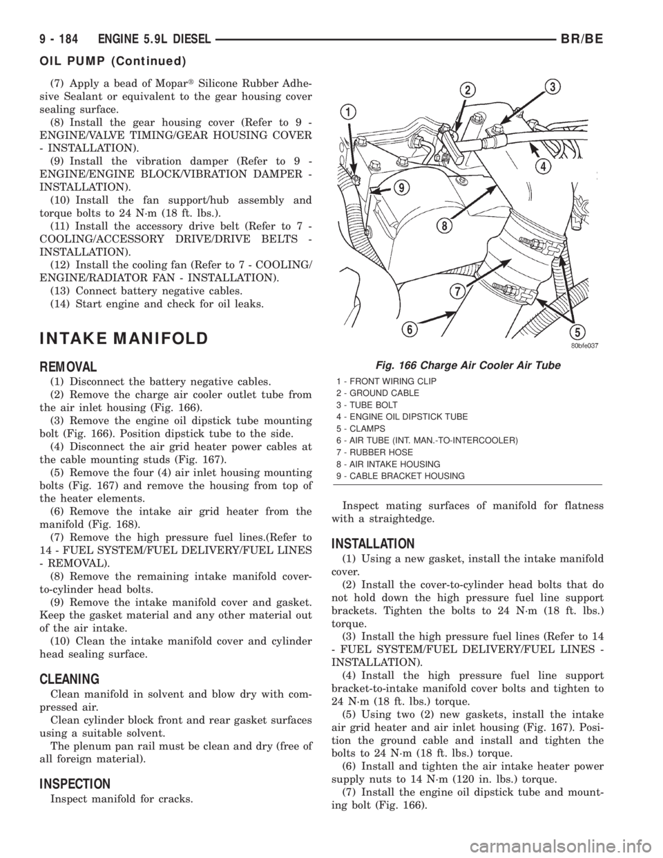
(2) Remove the charge air cooler outlet tube from
the air inlet housing (Fig. 166).
(3) Remove the engine oil dipstick tube mounting
bolt (Fig. 166). Position dipstick tube to the side.
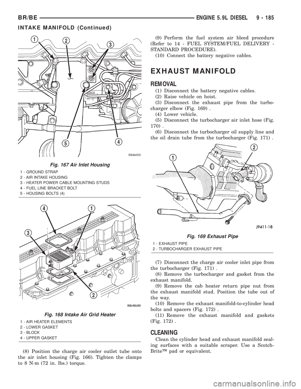
(4) Disconnect the air grid heater power cables at
the cable mounting studs (Fig. 167).
(5) Remove the four (4) air inlet housing mounting
bolts (Fig. 167) and remove the housing from top of
the heater elements.
(6) Remove the intake air grid heater from the
manifold (Fig. 168).
(7) Remove the high pressure fuel lines.(Refer to
14 - FUEL SYSTEM/FUEL DELIVERY/FUEL LINES
- REMOVAL).
(8) Remove the remaining intake manifold cover-
to-cylinder head bolts.
(9) Remove the intake manifold cover and gasket.
Keep the gasket material and any other material out
of the air intake.
(10) Clean the intake manifold cover and cylinder
head sealing surface.
CLEANING
Clean manifold in solvent and blow dry with com-
pressed air.
Clean cylinder block front and rear gasket surfaces
using a suitable solvent.
The plenum pan rail must be clean and dry (free of
all foreign material).
INSPECTION
Inspect manifold for cracks.Inspect mating surfaces of manifold for flatness
with a straightedge.
INSTALLATION
(1) Using a new gasket, install the intake manifold
cover.
(2) Install the cover-to-cylinder head bolts that do
not hold down the high pressure fuel line support
brackets. Tighten the bolts to 24 N´m (18 ft. lbs.)
torque.
(3) Install the high pressure fuel lines (Refer to 14
- FUEL SYSTEM/FUEL DELIVERY/FUEL LINES -
INSTALLATION).
(4) Install the high pressure fuel line support
bracket-to-intake manifold cover bolts and tighten to
24 N´m (18 ft. lbs.) torque.
(5) Using two (2) new gaskets, install the intake
air grid heater and air inlet housing (Fig. 167). Posi-
tion the ground cable and install and tighten the
bolts to 24 N´m (18 ft. lbs.) torque.
(6) Install and tighten the air intake heater power
supply nuts to 14 N´m (120 in. lbs.) torque.
(7) Install the engine oil dipstick tube and mount-
ing bolt (Fig. 166).
Fig. 166 Charge Air Cooler Air Tube
1 - FRONT WIRING CLIP
2 - GROUND CABLE
3 - TUBE BOLT
4 - ENGINE OIL DIPSTICK TUBE
5 - CLAMPS
6 - AIR TUBE (INT. MAN.-TO-INTERCOOLER)
7 - RUBBER HOSE
8 - AIR INTAKE HOUSING
9 - CABLE BRACKET HOUSING
9 - 184 ENGINE 5.9L DIESELBR/BE
OIL PUMP (Continued)
Page 1260 of 2255
(8) Position the charge air cooler outlet tube onto
the air inlet housing (Fig. 166). Tighten the clamps
to 8 N´m (72 in. lbs.) torque.(9) Perform the fuel system air bleed procedure
(Refer to 14 - FUEL SYSTEM/FUEL DELIVERY -
STANDARD PROCEDURE).
(10) Connect the battery negative cables.
EXHAUST MANIFOLD
REMOVAL
(1) Disconnect the battery negative cables.
(2) Raise vehicle on hoist.
(3) Disconnect the exhaust pipe from the turbo-
charger elbow (Fig. 169) .
(4) Lower vehicle.
(5) Disconnect the turbocharger air inlet hose (Fig.
170) .
(6) Disconnect the turbocharger oil supply line and
the oil drain tube from the turbocharger (Fig. 171) .
(7) Disconnect the charge air cooler inlet pipe from
the turbocharger (Fig. 171) .
(8) Remove the turbocharger and gasket from the
exhaust manifold.
(9) Remove the cab heater return pipe nut from
the exhaust manifold stud. Position the tube out of
the way.
(10) Remove the exhaust manifold-to-cylinder head
bolts and spacers (Fig. 172) .
(11) Remove the exhaust manifold and gaskets
(Fig. 172) .
CLEANING
Clean the cylinder head and exhaust manifold seal-
ing surfaces with a suitable scraper. Use a Scotch-
BriteŸ pad or equivalent.
Fig. 167 Air Inlet Housing
1 - GROUND STRAP
2 - AIR INTAKE HOUSING
3 - HEATER POWER CABLE MOUNTING STUDS
4 - FUEL LINE BRACKET BOLT
5 - HOUSING BOLTS (4)
Fig. 168 Intake Air Grid Heater
1 - AIR HEATER ELEMENTS
2 - LOWER GASKET
3 - BLOCK
4 - UPPER GASKET
Fig. 169 Exhaust Pipe
1 - EXHAUST PIPE
2 - TURBOCHARGER EXHAUST PIPE
BR/BEENGINE 5.9L DIESEL 9 - 185
INTAKE MANIFOLD (Continued)
Page 1262 of 2255
(7) Position the charge air cooler inlet pipe to the
turbocharger. With the clamp in position, tighten the
clamp nut to 8 N´m (72 in. lbs.) torque.
(8) Position the air inlet hose to the turbocharger
(Fig. 170). Tighten the clamp to 8 N´m (72 in. lbs.)
torque.
(9) Raise vehicle on hoist.
(10) Connect the exhaust pipe to the turbocharger
(Fig. 169) and tighten the bolts to 34 N´m (25 ft. lbs.)
torque.
(11) Lower the vehicle.
(12) Connect the battery negative cables.
(13) Start the engine to check for leaks.
VALVE TIMING
STANDARD PROCEDURE - TIMING
VERIFICATION
(1) Remove the cylinder head cover.
(2) Remove fuel injector from cylinder number 1.
(3) Remove the crankcase breather from the gear
housing cover.
(4) Using Special Tool 7471B rotate the engine
until the timing mark on the fuel pump gear is
aligned with the TDC mark on the gear housing
cover.
(5) Using a 8 in.x 1/4 in. dowel rod inserted into
cylinder number 1, rock the crankshaft back and
forth to verify piston number 1 is at TDC.
(6) With piston number 1 at TDC the timing mark
on the fuel pump gear should be aligned with the
TDC mark on the gear housing cover. If marks do not
line up, remove the gear housing cover.
(7) With cylinder number still at TDC, inspect the
keyway on the crankshaft gear for proper alignment
(12 o'clock position).
(8) If the keyway is not at 12 o'clock position
replace the crankshaft gear assembly.
(9) If the keyway is at 12 o'clock position, verify
timing mark alignment between the camshaft gear,
crankshaft gear and the fuel pump gear, if not
aligned inspect keyway on camshaft gear.
(10) Inspect keyway on camshaft gear for proper
alignment with the key in the camshaft, if alignment
is off replace the camshaft/gear assembly.
(11) If timing marks alignment is off and no dam-
age is found at either the crankshaft or camshaft
gear keyways, realign timing marks as necessary.
GEAR HOUSING
REMOVAL
(1) Disconnect the battery negative cables.
(2) Raise vehicle on hoist.(3) Partially drain engine coolant into container
suitable for re-use (Refer to 7 - COOLING - STAN-
DARD PROCEDURE).
(4) Lower vehicle.
(5) Remove radiator upper hose.
(6) Disconnect coolant recovery bottle hose from
radiator filler neck and lift bottle off of fan shroud.
(7) Disconnect windshield washer pump supply
hose and electrical connections and lift washer bottle
off of fan shroud.
(8) Remove the fan shroud-to-radiator mounting
bolts.
(9) Remove viscous fan/drive assembly (Refer to 7 -
COOLING/ENGINE/RADIATOR FAN - REMOVAL).
(10) Remove the accessory drive belt (Refer to 7 -
COOLING/ACCESSORY DRIVE/DRIVE BELTS -
REMOVAL).
(11) Remove the cooling fan support/hub from the
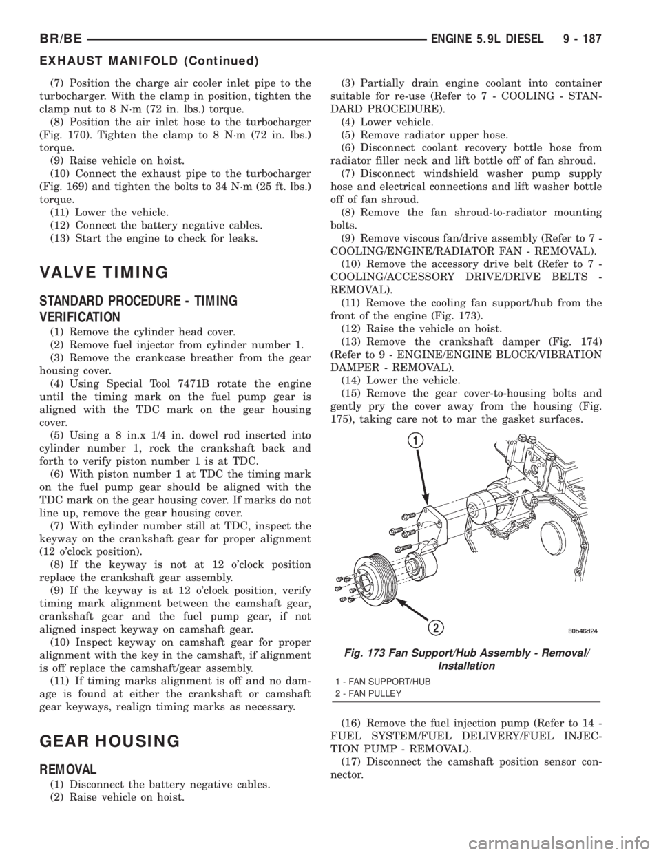
front of the engine (Fig. 173).
(12) Raise the vehicle on hoist.
(13) Remove the crankshaft damper (Fig. 174)
(Refer to 9 - ENGINE/ENGINE BLOCK/VIBRATION
DAMPER - REMOVAL).
(14) Lower the vehicle.
(15) Remove the gear cover-to-housing bolts and
gently pry the cover away from the housing (Fig.
175), taking care not to mar the gasket surfaces.
(16) Remove the fuel injection pump (Refer to 14 -
FUEL SYSTEM/FUEL DELIVERY/FUEL INJEC-
TION PUMP - REMOVAL).
(17) Disconnect the camshaft position sensor con-
nector.
Fig. 173 Fan Support/Hub Assembly - Removal/
Installation
1 - FAN SUPPORT/HUB
2 - FAN PULLEY
BR/BEENGINE 5.9L DIESEL 9 - 187
EXHAUST MANIFOLD (Continued)
Page 1264 of 2255
(8) Install and tighten the gear housing bolts to 24
N´m (18 ft. lbs.) torque.
(9) Install and tighten the oil pan bolts to 24 N´m
(18 ft. lbs.) torque.
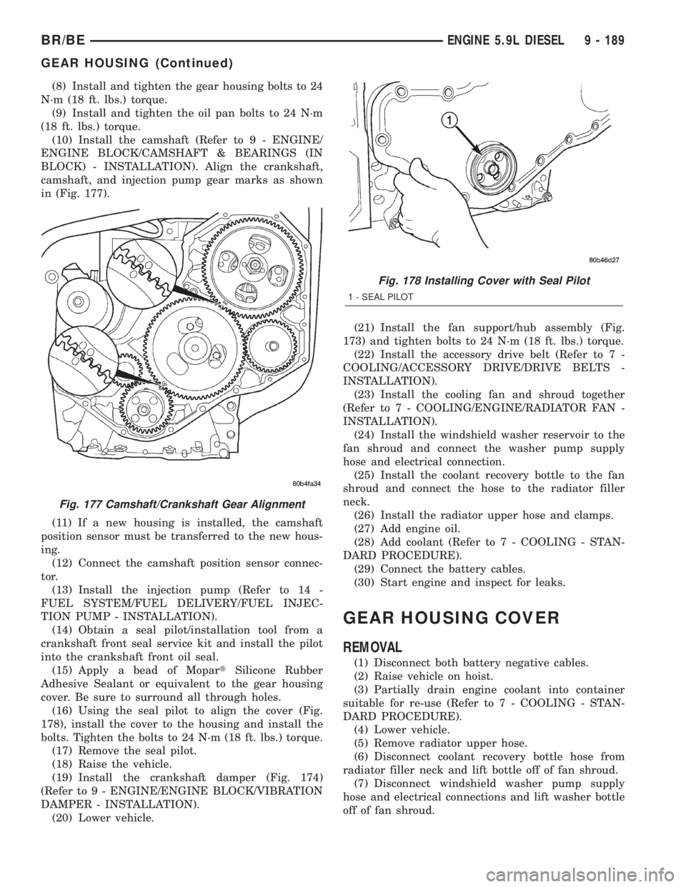
(10) Install the camshaft (Refer to 9 - ENGINE/
ENGINE BLOCK/CAMSHAFT & BEARINGS (IN
BLOCK) - INSTALLATION). Align the crankshaft,
camshaft, and injection pump gear marks as shown
in (Fig. 177).
(11) If a new housing is installed, the camshaft
position sensor must be transferred to the new hous-
ing.
(12) Connect the camshaft position sensor connec-
tor.
(13) Install the injection pump (Refer to 14 -
FUEL SYSTEM/FUEL DELIVERY/FUEL INJEC-
TION PUMP - INSTALLATION).
(14) Obtain a seal pilot/installation tool from a
crankshaft front seal service kit and install the pilot
into the crankshaft front oil seal.
(15) Apply a bead of MopartSilicone Rubber
Adhesive Sealant or equivalent to the gear housing
cover. Be sure to surround all through holes.
(16) Using the seal pilot to align the cover (Fig.
178), install the cover to the housing and install the
bolts. Tighten the bolts to 24 N´m (18 ft. lbs.) torque.
(17) Remove the seal pilot.
(18) Raise the vehicle.
(19) Install the crankshaft damper (Fig. 174)
(Refer to 9 - ENGINE/ENGINE BLOCK/VIBRATION
DAMPER - INSTALLATION).
(20) Lower vehicle.(21) Install the fan support/hub assembly (Fig.
173) and tighten bolts to 24 N´m (18 ft. lbs.) torque.
(22) Install the accessory drive belt (Refer to 7 -
COOLING/ACCESSORY DRIVE/DRIVE BELTS -
INSTALLATION).
(23) Install the cooling fan and shroud together
(Refer to 7 - COOLING/ENGINE/RADIATOR FAN -
INSTALLATION).
(24) Install the windshield washer reservoir to the
fan shroud and connect the washer pump supply
hose and electrical connection.
(25) Install the coolant recovery bottle to the fan
shroud and connect the hose to the radiator filler
neck.
(26) Install the radiator upper hose and clamps.
(27) Add engine oil.
(28) Add coolant (Refer to 7 - COOLING - STAN-
DARD PROCEDURE).
(29) Connect the battery cables.
(30) Start engine and inspect for leaks.
GEAR HOUSING COVER
REMOVAL
(1) Disconnect both battery negative cables.
(2) Raise vehicle on hoist.
(3) Partially drain engine coolant into container
suitable for re-use (Refer to 7 - COOLING - STAN-
DARD PROCEDURE).
(4) Lower vehicle.
(5) Remove radiator upper hose.
(6) Disconnect coolant recovery bottle hose from
radiator filler neck and lift bottle off of fan shroud.
(7) Disconnect windshield washer pump supply
hose and electrical connections and lift washer bottle
off of fan shroud.
Fig. 177 Camshaft/Crankshaft Gear Alignment
Fig. 178 Installing Cover with Seal Pilot
1 - SEAL PILOT
BR/BEENGINE 5.9L DIESEL 9 - 189
GEAR HOUSING (Continued)
Page 1266 of 2255
(8) Install the fan support/hub assy. (Fig. 179) and
tighten bolts to 24 N´m (18 ft. lbs.) torque.
(9) Install the accessory drive belt (Refer to 7 -
COOLING/ACCESSORY DRIVE/DRIVE BELTS -
INSTALLATION).
(10) Install the cooling fan and shroud together
(Refer to 7 - COOLING/ENGINE/RADIATOR FAN -
INSTALLATION).
(11) Install the windshield washer reservoir to the
fan shroud and connect the washer pump supply
hose and electrical connection.(12) Install the coolant recovery bottle to the fan
shroud and connect the hose to the radiator filler
neck.
(13) Install the radiator upper hose and clamps.
(14) Add coolant (Refer to 7 - COOLING - STAN-
DARD PROCEDURE).
(15) Connect the battery cables.
(16) Start engine and inspect for leaks.
BR/BEENGINE 5.9L DIESEL 9 - 191
GEAR HOUSING COVER (Continued)
Page 1276 of 2255
EXHAUST PIPE - 5.9L DIESEL
REMOVAL
(1) Disconnect the battery negative cables.
(2) Raise and support the vehicle on a hoist.
(3) Saturate the bolts and nuts with heat valve
lubricant. Allow 5 minutes for penetration.
(4) Remove the exhaust pipe-to-extension pipe
clamp. Separate the exhaust pipe and extension pipe.
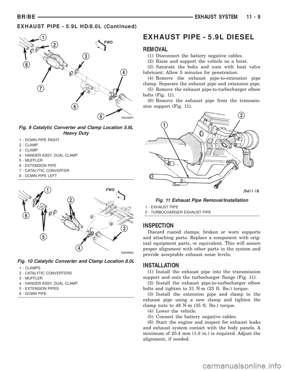
(5) Remove the exhaust pipe-to-turbocharger elbow
bolts (Fig. 11).
(6) Remove the exhaust pipe from the transmis-
sion support (Fig. 11).
INSPECTION
Discard rusted clamps, broken or worn supports
and attaching parts. Replace a component with orig-
inal equipment parts, or equivalent. This will assure
proper alignment with other parts in the system and
provide acceptable exhaust noise levels.
INSTALLATION
(1) Install the exhaust pipe into the transmission
support and onto the turbocharger flange (Fig. 11).
(2) Install the exhaust pipe-to-turbocharger elbow
bolts and tighten to 31 N´m (23 ft. lbs.) torque.
(3) Install the extension pipe and clamp to the
exhaust pipe using a new clamp and tighten the
clamp nuts to 48 N´m (35 ft. lbs.) torque.
(4) Lower the vehicle.
(5) Connect the battery negative cables.
(6) Start the engine and inspect for exhaust leaks
and exhaust system contact with the body panels. A
minimum of 25.4 mm (1.0 in.) is required. Adjust the
alignment, if needed.
Fig. 9 Catalytic Converter and Clamp Location 5.9L
Heavy Duty
1 - DOWN PIPE RIGHT
2 - CLAMP
3 - CLAMP
4 - HANGER ASSY. DUAL CLAMP
5 - MUFFLER
6 - EXTENSION PIPE
7 - CATALYTIC CONVERTER
8 - DOWN PIPE LEFT
Fig. 10 Catalytic Converter and Clamp Location 8.0L
1 - CLAMPS
2 - CATALYTIC CONVERTERS
3 - MUFFLER
4 - HANGER ASSY. DUAL CLAMP
5 - EXTENSION PIPES
6 - DOWN PIPE
Fig. 11 Exhaust Pipe Removal/Installation
1 - EXHAUST PIPE
2 - TURBOCHARGER EXHAUST PIPE
BR/BEEXHAUST SYSTEM 11 - 9
EXHAUST PIPE - 5.9L HD/8.0L (Continued)
Page 1278 of 2255
MUFFLER - 5.9L DIESEL
REMOVAL
(1) Disconnect the battery negative cables.
(2) Raise and support the vehicle.
(3) Remove the muffler to tail pipe and extension
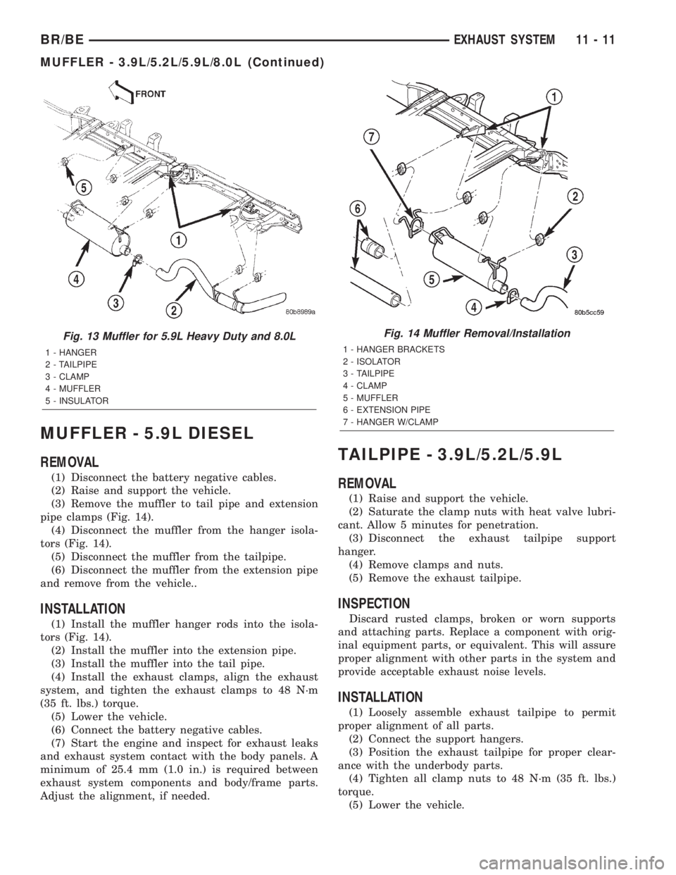
pipe clamps (Fig. 14).
(4) Disconnect the muffler from the hanger isola-
tors (Fig. 14).
(5) Disconnect the muffler from the tailpipe.
(6) Disconnect the muffler from the extension pipe
and remove from the vehicle..
INSTALLATION
(1) Install the muffler hanger rods into the isola-
tors (Fig. 14).
(2) Install the muffler into the extension pipe.
(3) Install the muffler into the tail pipe.
(4) Install the exhaust clamps, align the exhaust
system, and tighten the exhaust clamps to 48 N´m
(35 ft. lbs.) torque.
(5) Lower the vehicle.
(6) Connect the battery negative cables.
(7) Start the engine and inspect for exhaust leaks
and exhaust system contact with the body panels. A
minimum of 25.4 mm (1.0 in.) is required between
exhaust system components and body/frame parts.
Adjust the alignment, if needed.
TAILPIPE - 3.9L/5.2L/5.9L
REMOVAL
(1) Raise and support the vehicle.
(2) Saturate the clamp nuts with heat valve lubri-
cant. Allow 5 minutes for penetration.
(3) Disconnect the exhaust tailpipe support
hanger.
(4) Remove clamps and nuts.
(5) Remove the exhaust tailpipe.
INSPECTION
Discard rusted clamps, broken or worn supports
and attaching parts. Replace a component with orig-
inal equipment parts, or equivalent. This will assure
proper alignment with other parts in the system and
provide acceptable exhaust noise levels.
INSTALLATION
(1) Loosely assemble exhaust tailpipe to permit
proper alignment of all parts.
(2) Connect the support hangers.
(3) Position the exhaust tailpipe for proper clear-
ance with the underbody parts.
(4) Tighten all clamp nuts to 48 N´m (35 ft. lbs.)
torque.
(5) Lower the vehicle.
Fig. 13 Muffler for 5.9L Heavy Duty and 8.0L
1 - HANGER
2 - TAILPIPE
3 - CLAMP
4 - MUFFLER
5 - INSULATOR
Fig. 14 Muffler Removal/Installation
1 - HANGER BRACKETS
2 - ISOLATOR
3 - TAILPIPE
4 - CLAMP
5 - MUFFLER
6 - EXTENSION PIPE
7 - HANGER W/CLAMP
BR/BEEXHAUST SYSTEM 11 - 11
MUFFLER - 3.9L/5.2L/5.9L/8.0L (Continued)