2002 DODGE RAM battery
[x] Cancel search: batteryPage 1167 of 2255
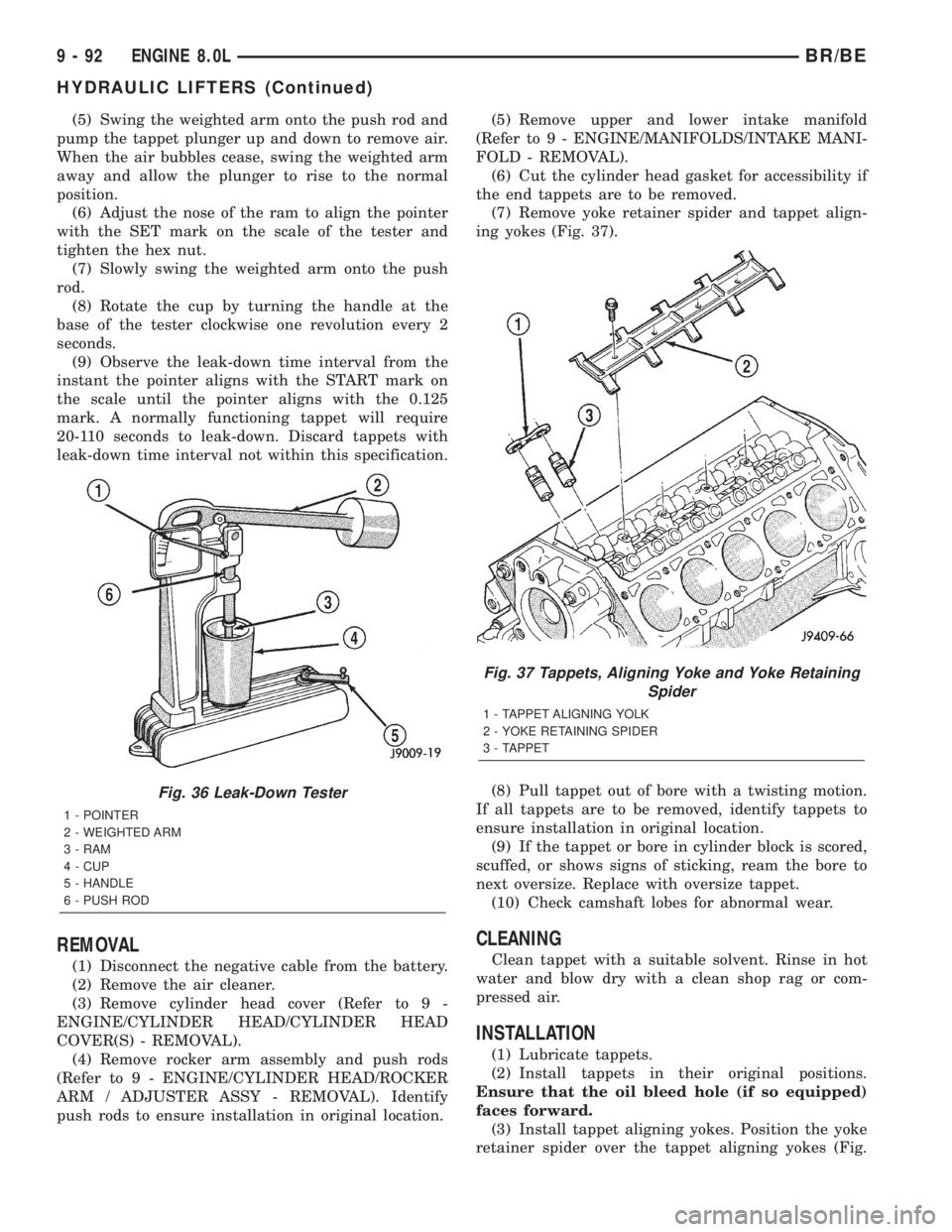
(5) Swing the weighted arm onto the push rod and
pump the tappet plunger up and down to remove air.
When the air bubbles cease, swing the weighted arm
away and allow the plunger to rise to the normal
position.
(6) Adjust the nose of the ram to align the pointer
with the SET mark on the scale of the tester and
tighten the hex nut.
(7) Slowly swing the weighted arm onto the push
rod.
(8) Rotate the cup by turning the handle at the
base of the tester clockwise one revolution every 2
seconds.
(9) Observe the leak-down time interval from the
instant the pointer aligns with the START mark on
the scale until the pointer aligns with the 0.125
mark. A normally functioning tappet will require
20-110 seconds to leak-down. Discard tappets with
leak-down time interval not within this specification.
REMOVAL
(1) Disconnect the negative cable from the battery.
(2) Remove the air cleaner.
(3) Remove cylinder head cover (Refer to 9 -
ENGINE/CYLINDER HEAD/CYLINDER HEAD
COVER(S) - REMOVAL).
(4) Remove rocker arm assembly and push rods
(Refer to 9 - ENGINE/CYLINDER HEAD/ROCKER
ARM / ADJUSTER ASSY - REMOVAL). Identify
push rods to ensure installation in original location.(5) Remove upper and lower intake manifold
(Refer to 9 - ENGINE/MANIFOLDS/INTAKE MANI-
FOLD - REMOVAL).
(6) Cut the cylinder head gasket for accessibility if
the end tappets are to be removed.
(7) Remove yoke retainer spider and tappet align-
ing yokes (Fig. 37).
(8) Pull tappet out of bore with a twisting motion.
If all tappets are to be removed, identify tappets to
ensure installation in original location.
(9) If the tappet or bore in cylinder block is scored,
scuffed, or shows signs of sticking, ream the bore to
next oversize. Replace with oversize tappet.
(10) Check camshaft lobes for abnormal wear.
CLEANING
Clean tappet with a suitable solvent. Rinse in hot
water and blow dry with a clean shop rag or com-
pressed air.
INSTALLATION
(1) Lubricate tappets.
(2) Install tappets in their original positions.
Ensure that the oil bleed hole (if so equipped)
faces forward.
(3) Install tappet aligning yokes. Position the yoke
retainer spider over the tappet aligning yokes (Fig.
Fig. 36 Leak-Down Tester
1 - POINTER
2 - WEIGHTED ARM
3 - RAM
4 - CUP
5 - HANDLE
6 - PUSH ROD
Fig. 37 Tappets, Aligning Yoke and Yoke Retaining
Spider
1 - TAPPET ALIGNING YOLK
2 - YOKE RETAINING SPIDER
3 - TAPPET
9 - 92 ENGINE 8.0LBR/BE
HYDRAULIC LIFTERS (Continued)
Page 1168 of 2255
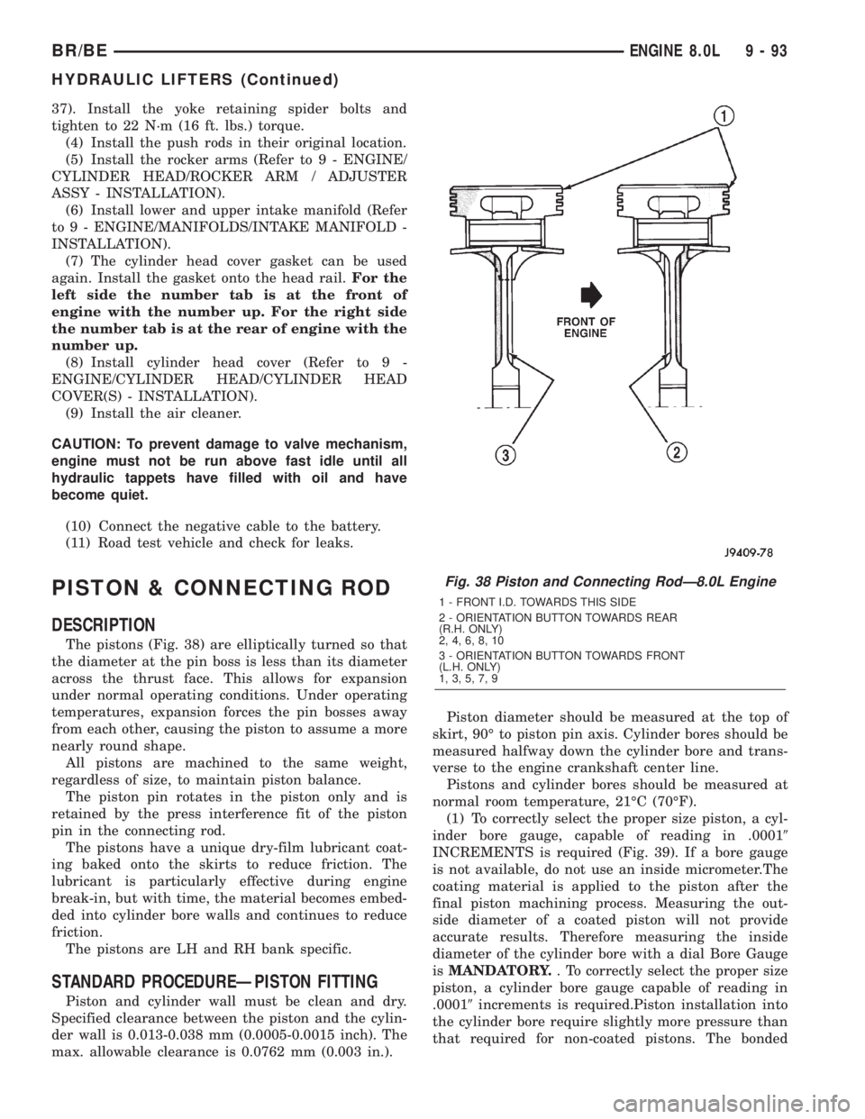
37). Install the yoke retaining spider bolts and
tighten to 22 N´m (16 ft. lbs.) torque.
(4) Install the push rods in their original location.
(5) Install the rocker arms (Refer to 9 - ENGINE/
CYLINDER HEAD/ROCKER ARM / ADJUSTER
ASSY - INSTALLATION).
(6) Install lower and upper intake manifold (Refer
to 9 - ENGINE/MANIFOLDS/INTAKE MANIFOLD -
INSTALLATION).
(7) The cylinder head cover gasket can be used
again. Install the gasket onto the head rail.For the
left side the number tab is at the front of
engine with the number up. For the right side
the number tab is at the rear of engine with the
number up.
(8) Install cylinder head cover (Refer to 9 -
ENGINE/CYLINDER HEAD/CYLINDER HEAD
COVER(S) - INSTALLATION).
(9) Install the air cleaner.
CAUTION: To prevent damage to valve mechanism,
engine must not be run above fast idle until all
hydraulic tappets have filled with oil and have
become quiet.
(10) Connect the negative cable to the battery.
(11) Road test vehicle and check for leaks.
PISTON & CONNECTING ROD
DESCRIPTION
The pistons (Fig. 38) are elliptically turned so that
the diameter at the pin boss is less than its diameter
across the thrust face. This allows for expansion
under normal operating conditions. Under operating
temperatures, expansion forces the pin bosses away
from each other, causing the piston to assume a more
nearly round shape.
All pistons are machined to the same weight,
regardless of size, to maintain piston balance.
The piston pin rotates in the piston only and is
retained by the press interference fit of the piston
pin in the connecting rod.
The pistons have a unique dry-film lubricant coat-
ing baked onto the skirts to reduce friction. The
lubricant is particularly effective during engine
break-in, but with time, the material becomes embed-
ded into cylinder bore walls and continues to reduce
friction.
The pistons are LH and RH bank specific.
STANDARD PROCEDUREÐPISTON FITTING
Piston and cylinder wall must be clean and dry.
Specified clearance between the piston and the cylin-
der wall is 0.013-0.038 mm (0.0005-0.0015 inch). The
max. allowable clearance is 0.0762 mm (0.003 in.).Piston diameter should be measured at the top of
skirt, 90É to piston pin axis. Cylinder bores should be
measured halfway down the cylinder bore and trans-
verse to the engine crankshaft center line.
Pistons and cylinder bores should be measured at
normal room temperature, 21ÉC (70ÉF).
(1) To correctly select the proper size piston, a cyl-
inder bore gauge, capable of reading in .00019
INCREMENTS is required (Fig. 39). If a bore gauge
is not available, do not use an inside micrometer.The
coating material is applied to the piston after the
final piston machining process. Measuring the out-
side diameter of a coated piston will not provide
accurate results. Therefore measuring the inside
diameter of the cylinder bore with a dial Bore Gauge
isMANDATORY.. To correctly select the proper size
piston, a cylinder bore gauge capable of reading in
.00019increments is required.Piston installation into
the cylinder bore require slightly more pressure than
that required for non-coated pistons. The bonded
Fig. 38 Piston and Connecting RodÐ8.0L Engine
1 - FRONT I.D. TOWARDS THIS SIDE
2 - ORIENTATION BUTTON TOWARDS REAR
(R.H. ONLY)
2, 4, 6, 8, 10
3 - ORIENTATION BUTTON TOWARDS FRONT
(L.H. ONLY)
1, 3, 5, 7, 9
BR/BEENGINE 8.0L 9 - 93
HYDRAULIC LIFTERS (Continued)
Page 1171 of 2255
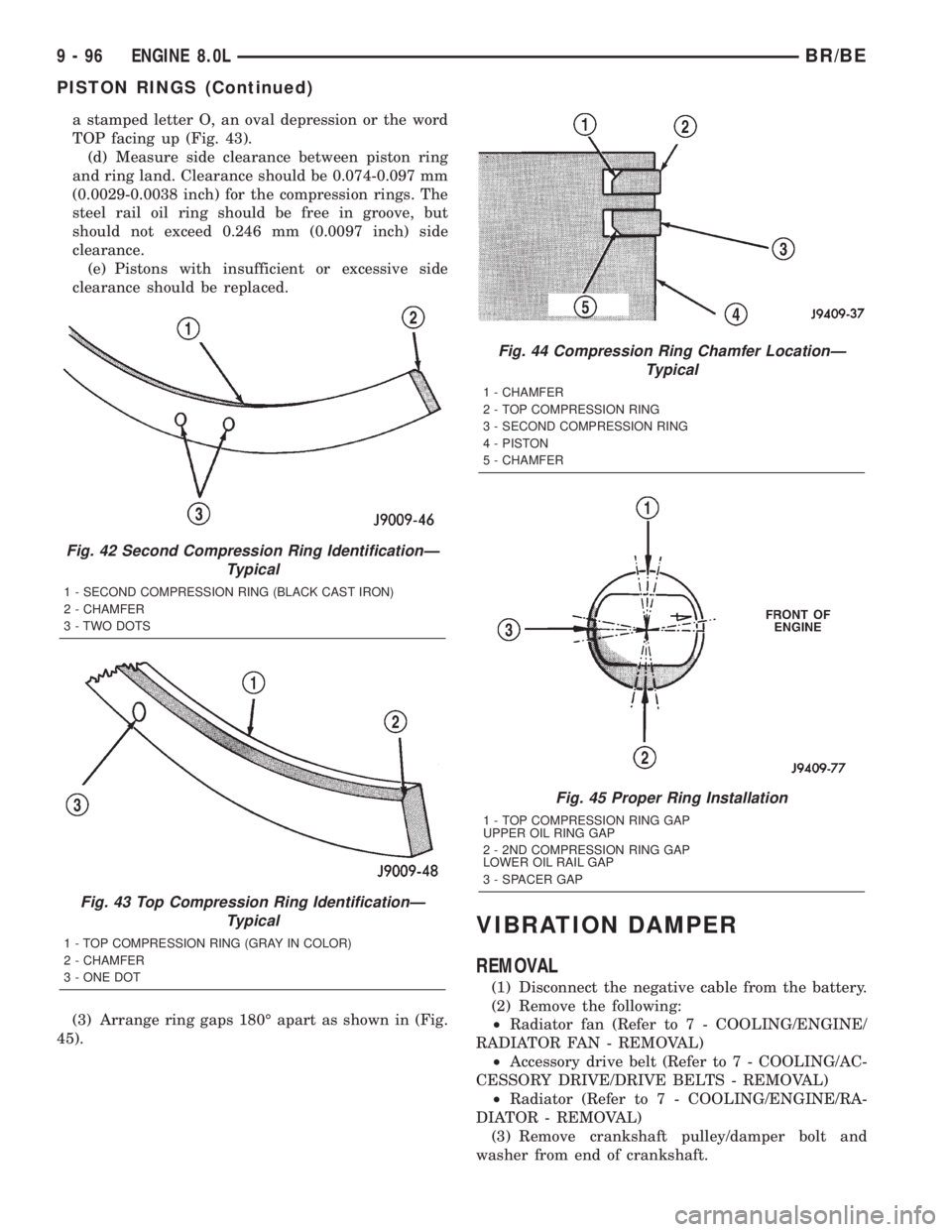
a stamped letter O, an oval depression or the word
TOP facing up (Fig. 43).
(d) Measure side clearance between piston ring
and ring land. Clearance should be 0.074-0.097 mm
(0.0029-0.0038 inch) for the compression rings. The
steel rail oil ring should be free in groove, but
should not exceed 0.246 mm (0.0097 inch) side
clearance.
(e) Pistons with insufficient or excessive side
clearance should be replaced.
(3) Arrange ring gaps 180É apart as shown in (Fig.
45).
VIBRATION DAMPER
REMOVAL
(1) Disconnect the negative cable from the battery.
(2) Remove the following:
²Radiator fan (Refer to 7 - COOLING/ENGINE/
RADIATOR FAN - REMOVAL)
²Accessory drive belt (Refer to 7 - COOLING/AC-
CESSORY DRIVE/DRIVE BELTS - REMOVAL)
²Radiator (Refer to 7 - COOLING/ENGINE/RA-
DIATOR - REMOVAL)
(3) Remove crankshaft pulley/damper bolt and
washer from end of crankshaft.
Fig. 42 Second Compression Ring IdentificationÐ
Typical
1 - SECOND COMPRESSION RING (BLACK CAST IRON)
2 - CHAMFER
3 - TWO DOTS
Fig. 43 Top Compression Ring IdentificationÐ
Typical
1 - TOP COMPRESSION RING (GRAY IN COLOR)
2 - CHAMFER
3 - ONE DOT
Fig. 44 Compression Ring Chamfer LocationÐ
Typical
1 - CHAMFER
2 - TOP COMPRESSION RING
3 - SECOND COMPRESSION RING
4 - PISTON
5 - CHAMFER
Fig. 45 Proper Ring Installation
1 - TOP COMPRESSION RING GAP
UPPER OIL RING GAP
2 - 2ND COMPRESSION RING GAP
LOWER OIL RAIL GAP
3 - SPACER GAP
9 - 96 ENGINE 8.0LBR/BE
PISTON RINGS (Continued)
Page 1172 of 2255
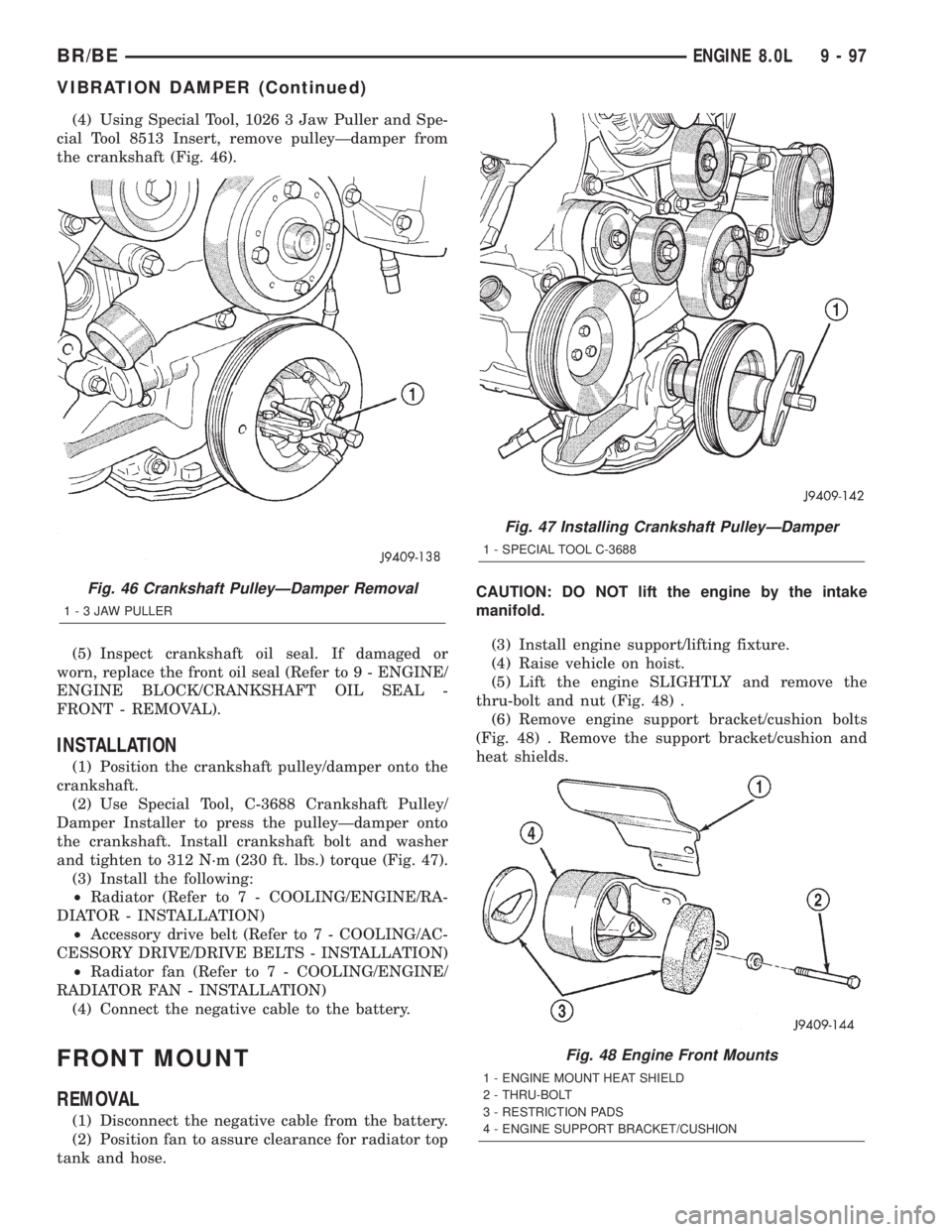
(4) Using Special Tool, 1026 3 Jaw Puller and Spe-
cial Tool 8513 Insert, remove pulleyÐdamper from
the crankshaft (Fig. 46).
(5) Inspect crankshaft oil seal. If damaged or
worn, replace the front oil seal (Refer to 9 - ENGINE/
ENGINE BLOCK/CRANKSHAFT OIL SEAL -
FRONT - REMOVAL).
INSTALLATION
(1) Position the crankshaft pulley/damper onto the
crankshaft.
(2) Use Special Tool, C-3688 Crankshaft Pulley/
Damper Installer to press the pulleyÐdamper onto
the crankshaft. Install crankshaft bolt and washer
and tighten to 312 N´m (230 ft. lbs.) torque (Fig. 47).
(3) Install the following:
²Radiator (Refer to 7 - COOLING/ENGINE/RA-
DIATOR - INSTALLATION)
²Accessory drive belt (Refer to 7 - COOLING/AC-
CESSORY DRIVE/DRIVE BELTS - INSTALLATION)
²Radiator fan (Refer to 7 - COOLING/ENGINE/
RADIATOR FAN - INSTALLATION)
(4) Connect the negative cable to the battery.
FRONT MOUNT
REMOVAL
(1) Disconnect the negative cable from the battery.
(2) Position fan to assure clearance for radiator top
tank and hose.CAUTION: DO NOT lift the engine by the intake
manifold.
(3) Install engine support/lifting fixture.
(4) Raise vehicle on hoist.
(5) Lift the engine SLIGHTLY and remove the
thru-bolt and nut (Fig. 48) .
(6) Remove engine support bracket/cushion bolts
(Fig. 48) . Remove the support bracket/cushion and
heat shields.
Fig. 46 Crankshaft PulleyÐDamper Removal
1-3JAWPULLER
Fig. 47 Installing Crankshaft PulleyÐDamper
1 - SPECIAL TOOL C-3688
Fig. 48 Engine Front Mounts
1 - ENGINE MOUNT HEAT SHIELD
2 - THRU-BOLT
3 - RESTRICTION PADS
4 - ENGINE SUPPORT BRACKET/CUSHION
BR/BEENGINE 8.0L 9 - 97
VIBRATION DAMPER (Continued)
Page 1177 of 2255
The acceptable levels are indicated between the ADD
and SAFE marks on the engine oil dipstick.
(1) Position vehicle on level surface.
(2) With engine OFF, allow approximately ten min-
utes for oil to settle to bottom of crankcase, remove
engine oil dipstick.
(3) Wipe dipstick clean.
(4) Install dipstick and verify it is seated in the
tube.
(5) Remove dipstick, with handle held above the
tip, take oil level reading.
(6) Add oil only if level is below the ADD mark on
dipstick.
ENGINE OIL CHANGE
Change engine oil at mileage and time intervals
described in the Maintenance Schedule. This infor-
mation can be found in the owner's manual.
TO CHANGE ENGINE OIL
Run engine until achieving normal operating tem-
perature.
(1) Position the vehicle on a level surface and turn
engine off.
(2) Hoist vehicle.
(3) Remove oil fill cap.
(4) Place a suitable drain pan under crankcase
drain.
(5) Remove drain plug from crankcase and allow
oil to drain into pan. Inspect drain plug threads for
stretching or other damage. Replace drain plug and
gasket if damaged.
(6) Install drain plug in crankcase.
(7) Change oil filter (Refer to 9 - ENGINE/LUBRI-
CATION/OIL FILTER - REMOVAL).
(8) Lower vehicle and fill crankcase with specified
type (Refer to LUBRICATION & MAINTENANCE/
FLUID TYPES - DESCRIPTION) and amount of
engine oil (Refer to LUBRICATION & MAINTE-
NANCE - SPECIFICATIONS).
(9) Install oil fill cap.
(10) Start engine and inspect for leaks.
(11) Stop engine and inspect oil level.
OIL FILTER
REMOVAL
All engines are equipped with a high quality full-
flow, disposable type oil filter. DaimlerChrysler Cor-
poration recommends a Mopartor equivalent oil
filter be used.
(1) Position a drain pan under the oil filter.
(2) Using a suitable oil filter wrench loosen filter.
(3) Rotate the oil filter counterclockwise to remove
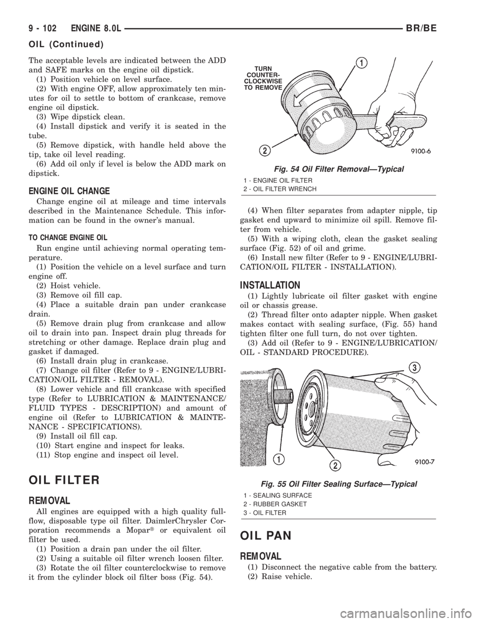
it from the cylinder block oil filter boss (Fig. 54).(4) When filter separates from adapter nipple, tip
gasket end upward to minimize oil spill. Remove fil-
ter from vehicle.
(5) With a wiping cloth, clean the gasket sealing
surface (Fig. 52) of oil and grime.
(6) Install new filter (Refer to 9 - ENGINE/LUBRI-
CATION/OIL FILTER - INSTALLATION).
INSTALLATION
(1) Lightly lubricate oil filter gasket with engine
oil or chassis grease.
(2) Thread filter onto adapter nipple. When gasket
makes contact with sealing surface, (Fig. 55) hand
tighten filter one full turn, do not over tighten.
(3) Add oil (Refer to 9 - ENGINE/LUBRICATION/
OIL - STANDARD PROCEDURE).
OIL PAN
REMOVAL
(1) Disconnect the negative cable from the battery.
(2) Raise vehicle.
Fig. 54 Oil Filter RemovalÐTypical
1 - ENGINE OIL FILTER
2 - OIL FILTER WRENCH
Fig. 55 Oil Filter Sealing SurfaceÐTypical
1 - SEALING SURFACE
2 - RUBBER GASKET
3 - OIL FILTER
9 - 102 ENGINE 8.0LBR/BE
OIL (Continued)
Page 1178 of 2255
(3) Drain engine oil.
(4) Remove left engine to transmission strut.
(5) Remove oil pan mounting bolts, pan and one-
piece gasket. The engine may have to be raised
slightly on 2WD vehicles.
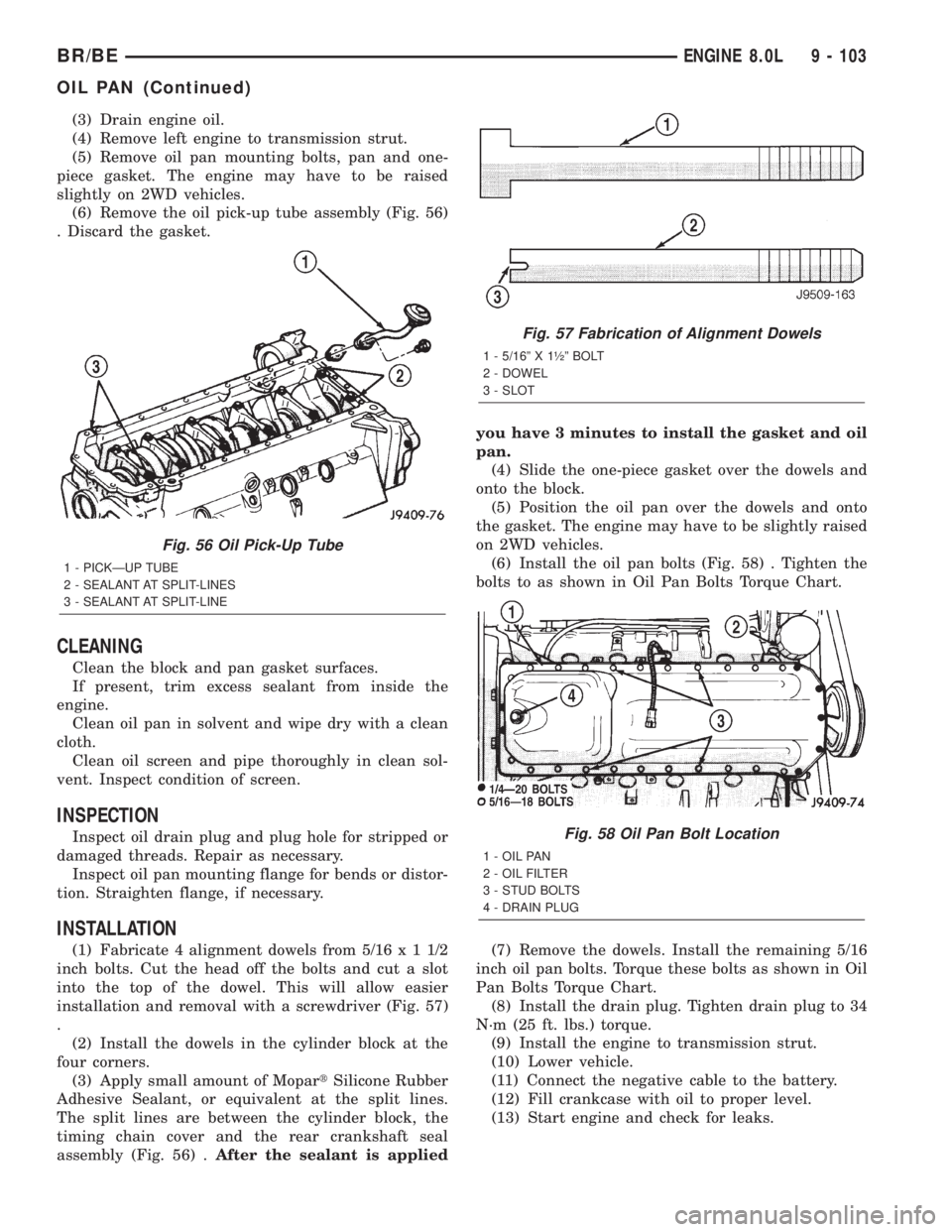
(6) Remove the oil pick-up tube assembly (Fig. 56)
. Discard the gasket.
CLEANING
Clean the block and pan gasket surfaces.
If present, trim excess sealant from inside the
engine.
Clean oil pan in solvent and wipe dry with a clean
cloth.
Clean oil screen and pipe thoroughly in clean sol-
vent. Inspect condition of screen.
INSPECTION
Inspect oil drain plug and plug hole for stripped or
damaged threads. Repair as necessary.
Inspect oil pan mounting flange for bends or distor-
tion. Straighten flange, if necessary.
INSTALLATION
(1) Fabricate 4 alignment dowels from 5/16x11/2
inch bolts. Cut the head off the bolts and cut a slot
into the top of the dowel. This will allow easier
installation and removal with a screwdriver (Fig. 57)
.
(2) Install the dowels in the cylinder block at the
four corners.
(3) Apply small amount of MopartSilicone Rubber
Adhesive Sealant, or equivalent at the split lines.
The split lines are between the cylinder block, the
timing chain cover and the rear crankshaft seal
assembly (Fig. 56) .After the sealant is appliedyou have 3 minutes to install the gasket and oil
pan.
(4) Slide the one-piece gasket over the dowels and
onto the block.
(5) Position the oil pan over the dowels and onto
the gasket. The engine may have to be slightly raised
on 2WD vehicles.
(6) Install the oil pan bolts (Fig. 58) . Tighten the
bolts to as shown in Oil Pan Bolts Torque Chart.
(7) Remove the dowels. Install the remaining 5/16
inch oil pan bolts. Torque these bolts as shown in Oil
Pan Bolts Torque Chart.
(8) Install the drain plug. Tighten drain plug to 34
N´m (25 ft. lbs.) torque.
(9) Install the engine to transmission strut.
(10) Lower vehicle.
(11) Connect the negative cable to the battery.
(12) Fill crankcase with oil to proper level.
(13) Start engine and check for leaks.
Fig. 56 Oil Pick-Up Tube
1 - PICKÐUP TUBE
2 - SEALANT AT SPLIT-LINES
3 - SEALANT AT SPLIT-LINE
Fig. 57 Fabrication of Alignment Dowels
1 - 5/16º X 1óº BOLT
2 - DOWEL
3 - SLOT
Fig. 58 Oil Pan Bolt Location
1 - OIL PAN
2 - OIL FILTER
3 - STUD BOLTS
4 - DRAIN PLUG
BR/BEENGINE 8.0L 9 - 103
OIL PAN (Continued)
Page 1182 of 2255
REMOVAL
(1) Disconnect the negative cable from the battery.
(2) Drain the cooling system (Refer to 7 - COOL-
ING - STANDARD PROCEDURE).
(3) Remove the accessory drive belt (Refer to 7 -
COOLING/ACCESSORY DRIVE/DRIVE BELTS -
REMOVAL).
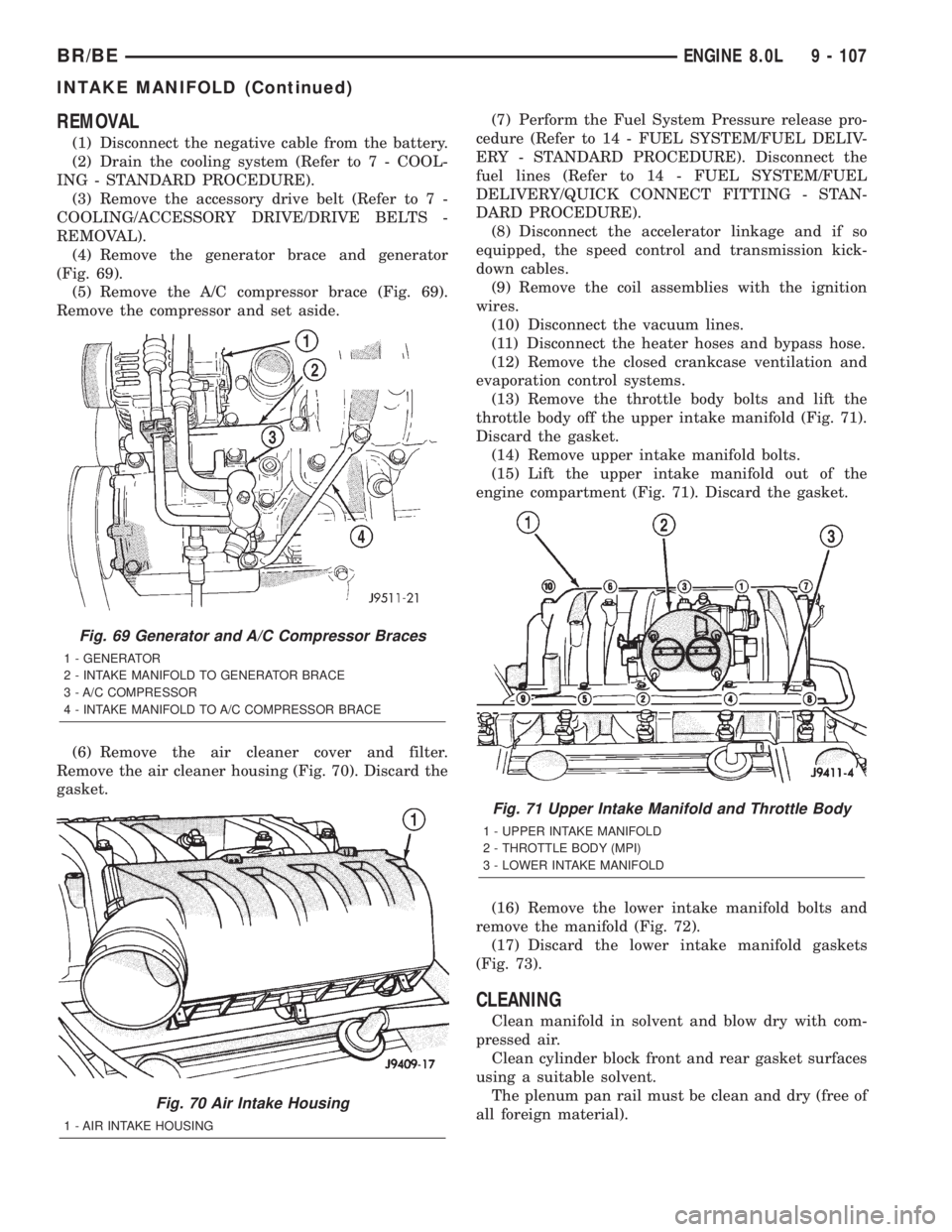
(4) Remove the generator brace and generator
(Fig. 69).
(5) Remove the A/C compressor brace (Fig. 69).
Remove the compressor and set aside.
(6) Remove the air cleaner cover and filter.
Remove the air cleaner housing (Fig. 70). Discard the
gasket.(7) Perform the Fuel System Pressure release pro-
cedure (Refer to 14 - FUEL SYSTEM/FUEL DELIV-
ERY - STANDARD PROCEDURE). Disconnect the
fuel lines (Refer to 14 - FUEL SYSTEM/FUEL
DELIVERY/QUICK CONNECT FITTING - STAN-
DARD PROCEDURE).
(8) Disconnect the accelerator linkage and if so
equipped, the speed control and transmission kick-
down cables.
(9) Remove the coil assemblies with the ignition
wires.
(10) Disconnect the vacuum lines.
(11) Disconnect the heater hoses and bypass hose.
(12) Remove the closed crankcase ventilation and
evaporation control systems.
(13) Remove the throttle body bolts and lift the
throttle body off the upper intake manifold (Fig. 71).
Discard the gasket.
(14) Remove upper intake manifold bolts.
(15) Lift the upper intake manifold out of the
engine compartment (Fig. 71). Discard the gasket.
(16) Remove the lower intake manifold bolts and
remove the manifold (Fig. 72).
(17) Discard the lower intake manifold gaskets
(Fig. 73).
CLEANING
Clean manifold in solvent and blow dry with com-
pressed air.
Clean cylinder block front and rear gasket surfaces
using a suitable solvent.
The plenum pan rail must be clean and dry (free of
all foreign material).
Fig. 69 Generator and A/C Compressor Braces
1 - GENERATOR
2 - INTAKE MANIFOLD TO GENERATOR BRACE
3 - A/C COMPRESSOR
4 - INTAKE MANIFOLD TO A/C COMPRESSOR BRACE
Fig. 70 Air Intake Housing
1 - AIR INTAKE HOUSING
Fig. 71 Upper Intake Manifold and Throttle Body
1 - UPPER INTAKE MANIFOLD
2 - THROTTLE BODY (MPI)
3 - LOWER INTAKE MANIFOLD
BR/BEENGINE 8.0L 9 - 107
INTAKE MANIFOLD (Continued)
Page 1184 of 2255
(15) Install the fuel lines (Refer to 14 - FUEL SYS-
TEM/FUEL DELIVERY/QUICK CONNECT FIT-
TING - STANDARD PROCEDURE).
(16) Using a new gasket, install the air cleaner
housing. Tighten the nuts to 11 N´m (96 in. lbs.)
torque. Install the air cleaner filter and cover.
(17) Install the A/C compressor (Refer to 24 -
HEATING & AIR CONDITIONING/PLUMBING/A/C
COMPRESSOR - INSTALLATION). Position the com-
pressor brace and install the bolts. Tighten the brace
bolts to 41 N´m (30 ft. lbs.) torque.
(18) Install the generator (Refer to 8 - ELECTRI-
CAL/CHARGING/GENERATOR - INSTALLATION).
Position the generator brace and install the bolts.
Tighten the brace bolts to 41 N´m (30 ft. lbs.) torque.
(19) Install the accessory drive belt (Refer to 7 -
COOLING/ACCESSORY DRIVE/DRIVE BELTS -
INSTALLATION).
(20) Fill cooling system (Refer to 7 - COOLING -
STANDARD PROCEDURE).
(21) Connect the negative cable to the battery.
(22) Start engine check for leaks.
EXHAUST MANIFOLD
DESCRIPTION
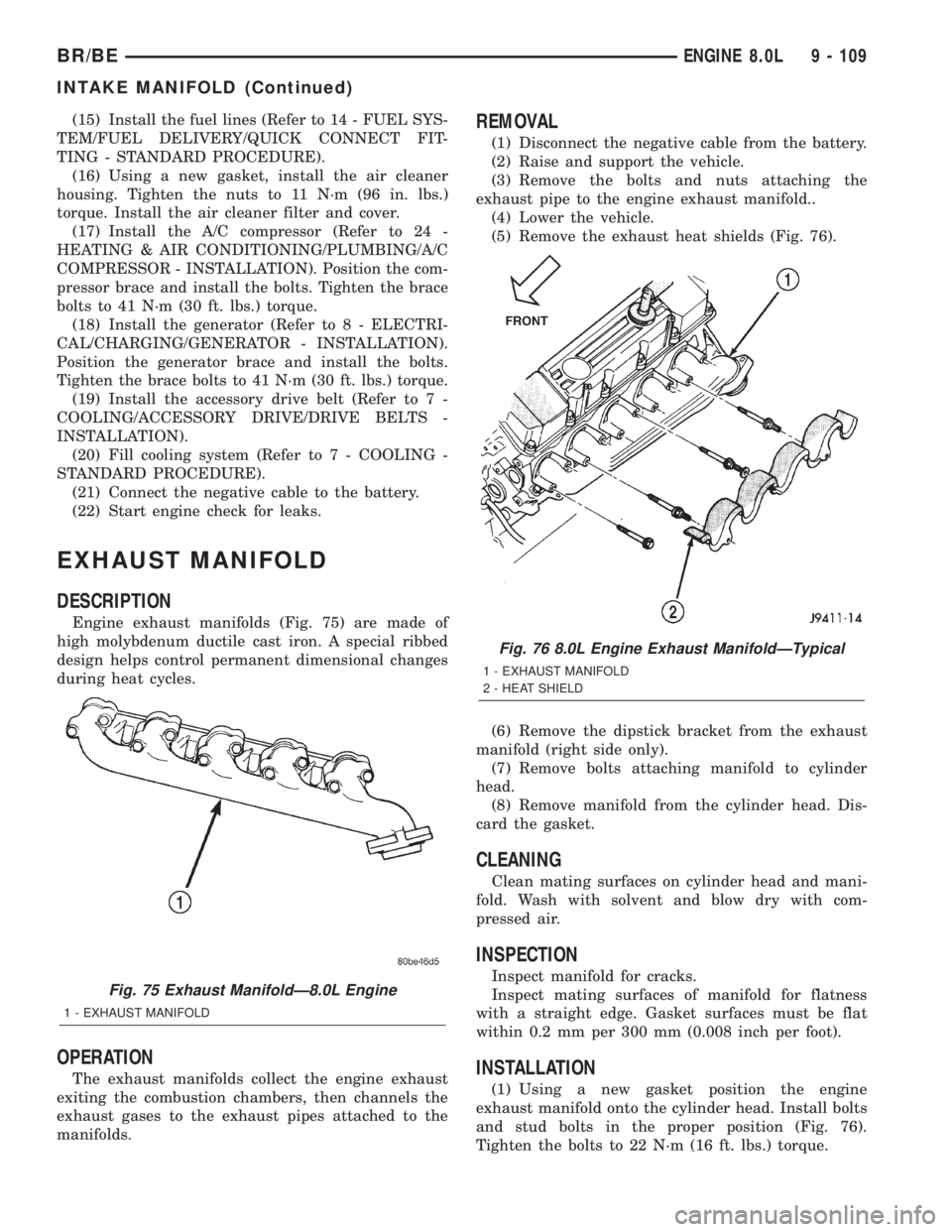
Engine exhaust manifolds (Fig. 75) are made of
high molybdenum ductile cast iron. A special ribbed
design helps control permanent dimensional changes
during heat cycles.
OPERATION
The exhaust manifolds collect the engine exhaust
exiting the combustion chambers, then channels the
exhaust gases to the exhaust pipes attached to the
manifolds.
REMOVAL
(1) Disconnect the negative cable from the battery.
(2) Raise and support the vehicle.
(3) Remove the bolts and nuts attaching the
exhaust pipe to the engine exhaust manifold..
(4) Lower the vehicle.
(5) Remove the exhaust heat shields (Fig. 76).
(6) Remove the dipstick bracket from the exhaust
manifold (right side only).
(7) Remove bolts attaching manifold to cylinder
head.
(8) Remove manifold from the cylinder head. Dis-
card the gasket.
CLEANING
Clean mating surfaces on cylinder head and mani-
fold. Wash with solvent and blow dry with com-
pressed air.
INSPECTION
Inspect manifold for cracks.
Inspect mating surfaces of manifold for flatness
with a straight edge. Gasket surfaces must be flat
within 0.2 mm per 300 mm (0.008 inch per foot).
INSTALLATION
(1) Using a new gasket position the engine
exhaust manifold onto the cylinder head. Install bolts
and stud bolts in the proper position (Fig. 76).
Tighten the bolts to 22 N´m (16 ft. lbs.) torque.
Fig. 75 Exhaust ManifoldÐ8.0L Engine
1 - EXHAUST MANIFOLD
Fig. 76 8.0L Engine Exhaust ManifoldÐTypical
1 - EXHAUST MANIFOLD
2 - HEAT SHIELD
BR/BEENGINE 8.0L 9 - 109
INTAKE MANIFOLD (Continued)