2002 DODGE RAM clutch
[x] Cancel search: clutchPage 1941 of 2255
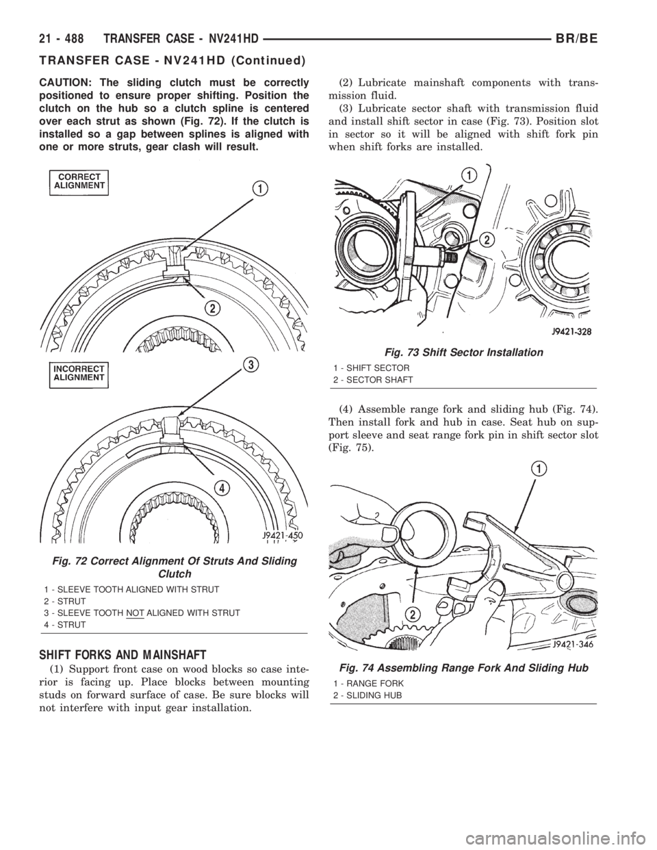
CAUTION: The sliding clutch must be correctly
positioned to ensure proper shifting. Position the
clutch on the hub so a clutch spline is centered
over each strut as shown (Fig. 72). If the clutch is
installed so a gap between splines is aligned with
one or more struts, gear clash will result.
SHIFT FORKS AND MAINSHAFT
(1) Support front case on wood blocks so case inte-
rior is facing up. Place blocks between mounting
studs on forward surface of case. Be sure blocks will
not interfere with input gear installation.(2) Lubricate mainshaft components with trans-
mission fluid.
(3) Lubricate sector shaft with transmission fluid
and install shift sector in case (Fig. 73). Position slot
in sector so it will be aligned with shift fork pin
when shift forks are installed.
(4) Assemble range fork and sliding hub (Fig. 74).
Then install fork and hub in case. Seat hub on sup-
port sleeve and seat range fork pin in shift sector slot
(Fig. 75).
Fig. 72 Correct Alignment Of Struts And Sliding
Clutch
1 - SLEEVE TOOTH ALIGNED WITH STRUT
2 - STRUT
3 - SLEEVE TOOTH NOT ALIGNED WITH STRUT
4 - STRUT
Fig. 73 Shift Sector Installation
1 - SHIFT SECTOR
2 - SECTOR SHAFT
Fig. 74 Assembling Range Fork And Sliding Hub
1 - RANGE FORK
2 - SLIDING HUB
21 - 488 TRANSFER CASE - NV241HDBR/BE
TRANSFER CASE - NV241HD (Continued)
Page 1942 of 2255
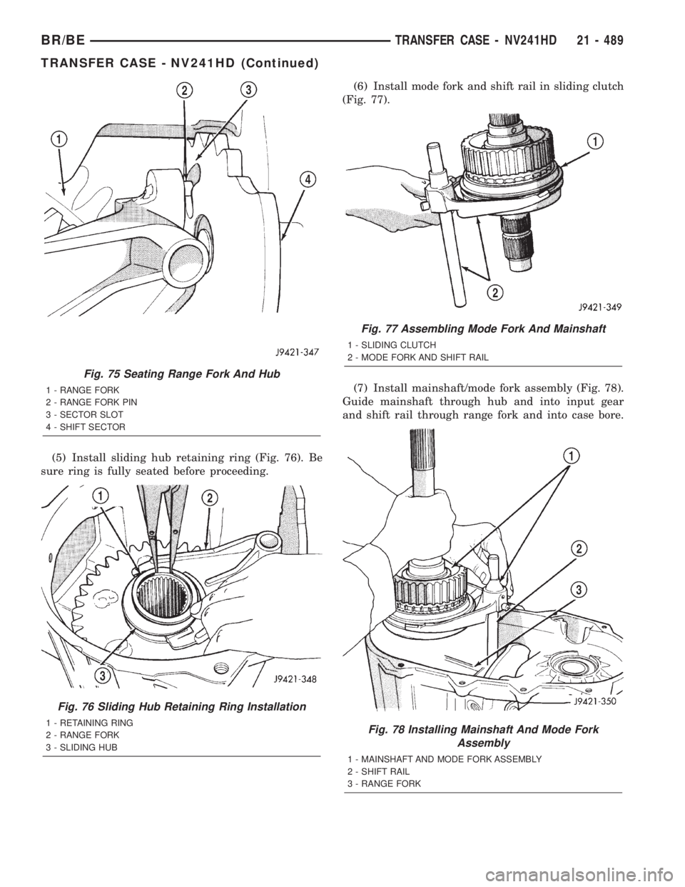
(5) Install sliding hub retaining ring (Fig. 76). Be
sure ring is fully seated before proceeding.(6) Install mode fork and shift rail in sliding clutch
(Fig. 77).
(7) Install mainshaft/mode fork assembly (Fig. 78).
Guide mainshaft through hub and into input gear
and shift rail through range fork and into case bore.
Fig. 75 Seating Range Fork And Hub
1 - RANGE FORK
2 - RANGE FORK PIN
3 - SECTOR SLOT
4 - SHIFT SECTOR
Fig. 76 Sliding Hub Retaining Ring Installation
1 - RETAINING RING
2 - RANGE FORK
3 - SLIDING HUB
Fig. 77 Assembling Mode Fork And Mainshaft
1 - SLIDING CLUTCH
2 - MODE FORK AND SHIFT RAIL
Fig. 78 Installing Mainshaft And Mode Fork
Assembly
1 - MAINSHAFT AND MODE FORK ASSEMBLY
2 - SHIFT RAIL
3 - RANGE FORK
BR/BETRANSFER CASE - NV241HD 21 - 489
TRANSFER CASE - NV241HD (Continued)
Page 1944 of 2255
FRONT OUTPUT SHAFT AND DRIVE CHAIN
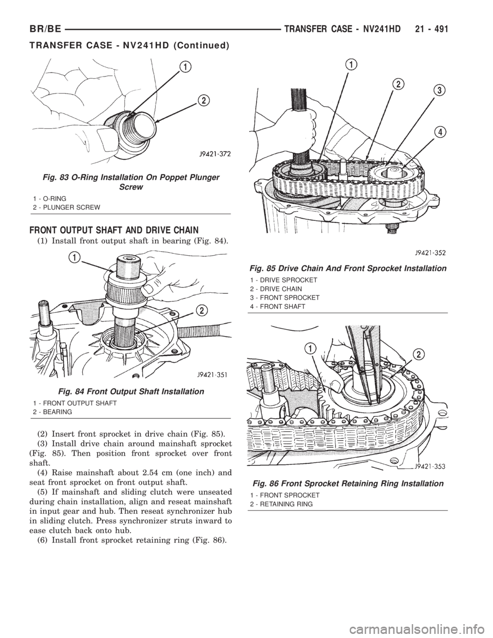
(1) Install front output shaft in bearing (Fig. 84).
(2) Insert front sprocket in drive chain (Fig. 85).
(3) Install drive chain around mainshaft sprocket
(Fig. 85). Then position front sprocket over front
shaft.
(4) Raise mainshaft about 2.54 cm (one inch) and
seat front sprocket on front output shaft.
(5) If mainshaft and sliding clutch were unseated
during chain installation, align and reseat mainshaft
in input gear and hub. Then reseat synchronizer hub
in sliding clutch. Press synchronizer struts inward to
ease clutch back onto hub.
(6) Install front sprocket retaining ring (Fig. 86).
Fig. 83 O-Ring Installation On Poppet Plunger
Screw
1 - O-RING
2 - PLUNGER SCREW
Fig. 84 Front Output Shaft Installation
1 - FRONT OUTPUT SHAFT
2 - BEARING
Fig. 85 Drive Chain And Front Sprocket Installation
1 - DRIVE SPROCKET
2 - DRIVE CHAIN
3 - FRONT SPROCKET
4 - FRONT SHAFT
Fig. 86 Front Sprocket Retaining Ring Installation
1 - FRONT SPROCKET
2 - RETAINING RING
BR/BETRANSFER CASE - NV241HD 21 - 491
TRANSFER CASE - NV241HD (Continued)
Page 1945 of 2255
(7) Realign sliding clutch on synchronizer hub if
necessary. Press synchronizer struts inward to ease
realignment. Be sure mainshaft is fully seated before
proceeding.
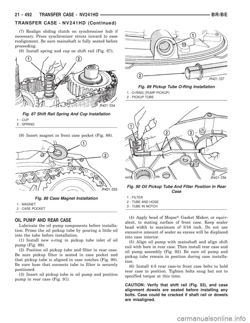
(8) Install spring and cup on shift rail (Fig. 87).
(9) Insert magnet in front case pocket (Fig. 88).
OIL PUMP AND REAR CASE
Lubricate the oil pump components before installa-
tion. Prime the oil pickup tube by pouring a little oil
into the tube before installation.
(1) Install new o-ring in pickup tube inlet of oil
pump (Fig. 89).
(2) Position oil pickup tube and filter in rear case.
Be sure pickup filter is seated in case pocket and
that pickup tube is aligned in case notches (Fig. 90).
Be sure hose that connects tube to filter is securely
positioned.
(3) Insert oil pickup tube in oil pump and position
pump in rear case (Fig. 91).(4) Apply bead of MopartGasket Maker, or equiv-
alent, to mating surface of front case. Keep sealer
bead width to maximum of 3/16 inch. Do not use
excessive amount of sealer as excess will be displaced
into case interior.
(5) Align oil pump with mainshaft and align shift
rail with bore in rear case. Then install rear case and
oil pump assembly (Fig. 92). Be sure oil pump and
pickup tube remain in position during case installa-
tion.
(6) Install 4-5 rear case-to front case bolts to hold
rear case in position. Tighten bolts snug but not to
specified torque at this time.
CAUTION: Verify that shift rail (Fig. 93), and case
alignment dowels are seated before installing any
bolts. Case could be cracked if shaft rail or dowels
are misaligned.
Fig. 87 Shift Rail Spring And Cup Installation
1 - CUP
2 - SPRING
Fig. 88 Case Magnet Installation
1 - MAGNET
2 - CASE POCKET
Fig. 89 Pickup Tube O-Ring Installation
1 - O-RING (PUMP PICKUP)
2 - PICKUP TUBE
Fig. 90 Oil Pickup Tube And Filter Position In Rear
Case
1 - FILTER
2 - TUBE AND HOSE
3 - TUBE IN NOTCH
21 - 492 TRANSFER CASE - NV241HDBR/BE
TRANSFER CASE - NV241HD (Continued)
Page 2123 of 2255
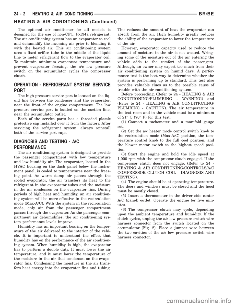
The optional air conditioner for all models is
designed for the use of non-CFC, R-134a refrigerant.
The air conditioning system has an evaporator to cool
and dehumidify the incoming air prior to blending it
with the heated air. This air conditioning system
uses a fixed orifice tube in the middle of the liquid
line to meter refrigerant flow to the evaporator coil.
To maintain minimum evaporator temperature and
prevent evaporator freezing, the a/c low pressure
switch on the accumulator cycles the compressor
clutch.
OPERATION - REFRIGERANT SYSTEM SERVICE
PORT
The high pressure service port is located on the liq-
uid line between the condenser and the evaporator,
near the front of the engine compartment. The low
pressure service port is located on the suction line,
near the accumulator outlet.
Each of the service ports has a threaded plastic
protective cap installed over it from the factory. After
servicing the refrigerant system, always reinstall
both of the service port caps.
DIAGNOSIS AND TESTING - A/C
PERFORMANCE
The air conditioning system is designed to provide
the passenger compartment with low temperature
and low humidity air. The evaporator, located in the
HVAC housing on the dash panel below the instru-
ment panel, is cooled to temperatures near the freez-
ing point. As warm damp air passes through the
cooled evaporator, the air transfers its heat to the
refrigerant in the evaporator tubes and the moisture
in the air condenses on the evaporator fins. During
periods of high heat and humidity, an air condition-
ing system will be more effective in the recirculation
mode (Max-A/C). With the system in the recirculation
mode, only air from the passenger compartment
passes through the evaporator. As the passenger com-
partment air dehumidifies, the air conditioning sys-
tem performance levels improve.
Humidity has an important bearing on the temper-
ature of the air delivered to the interior of the vehi-
cle. It is important to understand the effect that
humidity has on the performance of the air condition-
ing system. When humidity is high, the evaporator
has to perform a double duty. It must lower the air
temperature, and it must lower the temperature of
the moisture in the air that condenses on the evapo-
rator fins. Condensing the moisture in the air trans-
fers heat energy into the evaporator fins and tubing.This reduces the amount of heat the evaporator can
absorb from the air. High humidity greatly reduces
the ability of the evaporator to lower the temperature
of the air.
However, evaporator capacity used to reduce the
amount of moisture in the air is not wasted. Wring-
ing some of the moisture out of the air entering the
vehicle adds to the comfort of the passengers.
Although, an owner may expect too much from their
air conditioning system on humid days. A perfor-
mance test is the best way to determine whether the
system is performing up to standard. This test also
provides valuable clues as to the possible cause of
trouble with the air conditioning system.
Before proceeding, (Refer to 24 - HEATING & AIR
CONDITIONING/PLUMBING - WARNING) and
(Refer to 24 - HEATING & AIR CONDITIONING/
PLUMBING - CAUTION). The air temperature in
the test room and in the vehicle must be a minimum
of 21É C (70É F) for this test.
(1) Connect a tachometer and a manifold gauge
set.
(2) Set the a/c heater mode control switch knob to
the recirculation mode (Max-A/C) position, the tem-
perature control knob to the full cool position, and
the blower motor switch to the highest speed posi-
tion.
(3) Start the engine and hold the idle speed at
1,000 rpm with the compressor clutch engaged. If the
compressor clutch does not engage, (Refer to 24 -
HEATING & AIR CONDITIONING/CONTROLS/A/C
COMPRESSOR CLUTCH COIL - DIAGNOSIS AND
TESTING).
(4) The engine should be at operating temperature.
The doors and windows must be closed and the hood
must be mostly closed.
(5) Insert a thermometer in the driver side center
A/C (panel) outlet. Operate the engine for five min-
utes.
(6) The compressor clutch may cycle, depending
upon the ambient temperature and humidity. If the
clutch cycles, unplug the a/c low pressure switch wire
harness connector from the switch located on the
accumulator (Fig. 2). Place a jumper wire between
the two cavities of the a/c low pressure switch wire
harness connector.
24 - 2 HEATING & AIR CONDITIONINGBR/BE
HEATING & AIR CONDITIONING (Continued)
Page 2124 of 2255
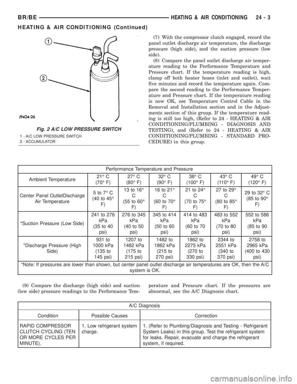
(7) With the compressor clutch engaged, record the
panel outlet discharge air temperature, the discharge
pressure (high side), and the suction pressure (low
side).
(8) Compare the panel outlet discharge air temper-
ature reading to the Performance Temperature and
Pressure chart. If the temperature reading is high,
clamp off both heater hoses (inlet and outlet), wait
five minutes and record the temperature again. Com-
pare the second reading to the Performance Temper-
ature and Pressure chart. If the temperature reading
is now OK, see Temperature Control Cable in the
Removal and Installation section and in the Adjust-
ments section of this group. If the temperature read-
ing is still too high, (Refer to 24 - HEATING & AIR
CONDITIONING/PLUMBING - DIAGNOSIS AND
TESTING), and (Refer to 24 - HEATING & AIR
CONDITIONING/PLUMBING - STANDARD PRO-
CEDURE) in this group.
Performance Temperature and Pressure
Ambient Temperature21É C
(70É F)27É C
(80É F)32É C
(90É F)38É C
(100É F)43É C
(110É F)49É C
(120É F)
Center Panel OutletDischarge
Air Temperature5to7ÉC
(40 to 45É
F)13 to 16É
C
(55 to 60É
F)16 to 21É
C
(60 to 70É
F)21 to 24É
C
(70 to 75É
F)27 to 29É
C
(80 to 85É
F)29 to 32É C
(85 to 90É
F)
*Suction Pressure (Low Side)241 to 276
kPa
(35 to 40
psi)276 to 345
kPa
(40 to 50
psi)345 to 414
kPa
(50 to 60
psi)414 to 483
kPa
(60 to 70
psi)483 to 552
kPa
(70 to 80
psi)552 to 586
kPa
(85 to 90
psi)
*Discharge Pressure (High
Side)931 to
1000 kPa
(135 to
145 psi)1207 to
1482 kPa
(175 to
215 psi)1482 to
1862 kPa
(215 to
270 psi)1862 to
2275 kPa
(270 to
330 psi)2344 to
2551 kPa
(340 to
370 psi)2758 to
2965 kPa
(400 to 430
psi)
*Note: If pressures are lower than shown, but center panel outlet discharge air temperatures are OK, then the A/C
system is OK.
(9) Compare the discharge (high side) and suction
(low side) pressure readings to the Performance Tem-perature and Pressure chart. If the pressures are
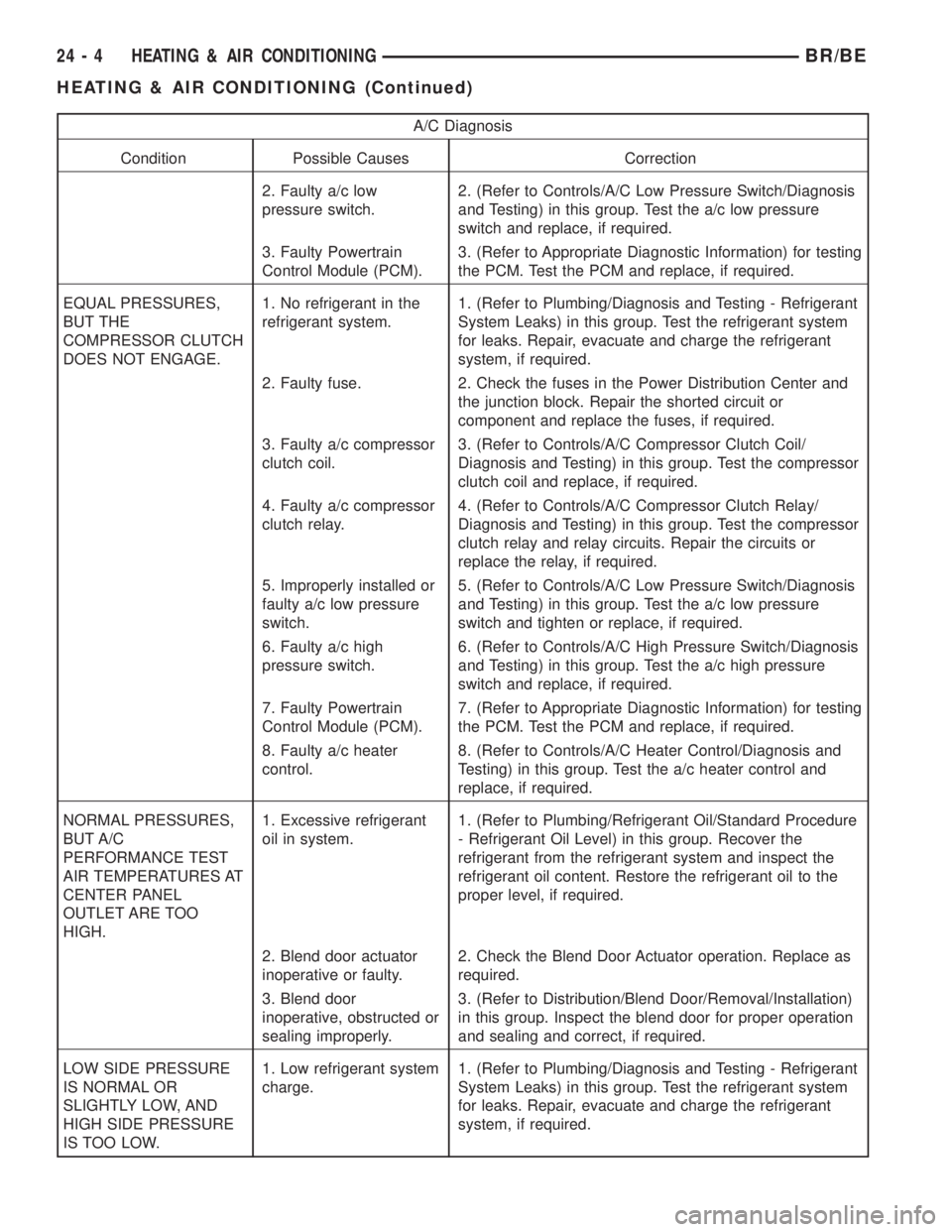
abnormal, see the A/C Diagnosis chart.
A/C Diagnosis
Condition Possible Causes Correction
RAPID COMPRESSOR
CLUTCH CYCLING (TEN
OR MORE CYCLES PER
MINUTE).1. Low refrigerant system
charge.1. (Refer to Plumbing/Diagnosis and Testing - Refrigerant
System Leaks) in this group. Test the refrigerant system
for leaks. Repair, evacuate and charge the refrigerant
system, if required.
Fig. 2 A/C LOW PRESSURE SWITCH
1 - A/C LOW PRESSURE SWITCH
2 - ACCUMULATOR
BR/BEHEATING & AIR CONDITIONING 24 - 3
HEATING & AIR CONDITIONING (Continued)
Page 2125 of 2255
A/C Diagnosis
Condition Possible Causes Correction
2. Faulty a/c low
pressure switch.2. (Refer to Controls/A/C Low Pressure Switch/Diagnosis
and Testing) in this group. Test the a/c low pressure
switch and replace, if required.
3. Faulty Powertrain
Control Module (PCM).3. (Refer to Appropriate Diagnostic Information) for testing
the PCM. Test the PCM and replace, if required.
EQUAL PRESSURES,
BUT THE
COMPRESSOR CLUTCH
DOES NOT ENGAGE.1. No refrigerant in the
refrigerant system.1. (Refer to Plumbing/Diagnosis and Testing - Refrigerant
System Leaks) in this group. Test the refrigerant system
for leaks. Repair, evacuate and charge the refrigerant
system, if required.
2. Faulty fuse. 2. Check the fuses in the Power Distribution Center and
the junction block. Repair the shorted circuit or
component and replace the fuses, if required.
3. Faulty a/c compressor
clutch coil.3. (Refer to Controls/A/C Compressor Clutch Coil/
Diagnosis and Testing) in this group. Test the compressor
clutch coil and replace, if required.
4. Faulty a/c compressor
clutch relay.4. (Refer to Controls/A/C Compressor Clutch Relay/
Diagnosis and Testing) in this group. Test the compressor
clutch relay and relay circuits. Repair the circuits or
replace the relay, if required.
5. Improperly installed or
faulty a/c low pressure
switch.5. (Refer to Controls/A/C Low Pressure Switch/Diagnosis
and Testing) in this group. Test the a/c low pressure
switch and tighten or replace, if required.
6. Faulty a/c high
pressure switch.6. (Refer to Controls/A/C High Pressure Switch/Diagnosis
and Testing) in this group. Test the a/c high pressure
switch and replace, if required.
7. Faulty Powertrain
Control Module (PCM).7. (Refer to Appropriate Diagnostic Information) for testing
the PCM. Test the PCM and replace, if required.
8. Faulty a/c heater
control.8. (Refer to Controls/A/C Heater Control/Diagnosis and
Testing) in this group. Test the a/c heater control and
replace, if required.
NORMAL PRESSURES,
BUT A/C
PERFORMANCE TEST
AIR TEMPERATURES AT
CENTER PANEL
OUTLET ARE TOO
HIGH.1. Excessive refrigerant
oil in system.1. (Refer to Plumbing/Refrigerant Oil/Standard Procedure
- Refrigerant Oil Level) in this group. Recover the
refrigerant from the refrigerant system and inspect the
refrigerant oil content. Restore the refrigerant oil to the
proper level, if required.
2. Blend door actuator
inoperative or faulty.2. Check the Blend Door Actuator operation. Replace as
required.
3. Blend door
inoperative, obstructed or
sealing improperly.3. (Refer to Distribution/Blend Door/Removal/Installation)
in this group. Inspect the blend door for proper operation
and sealing and correct, if required.
LOW SIDE PRESSURE
IS NORMAL OR
SLIGHTLY LOW, AND
HIGH SIDE PRESSURE
IS TOO LOW.1. Low refrigerant system
charge.1. (Refer to Plumbing/Diagnosis and Testing - Refrigerant
System Leaks) in this group. Test the refrigerant system
for leaks. Repair, evacuate and charge the refrigerant
system, if required.
24 - 4 HEATING & AIR CONDITIONINGBR/BE
HEATING & AIR CONDITIONING (Continued)
Page 2129 of 2255
Item Description Notes
Blower Motor hardwired to
control headresistor block
Cooling Fan viscous fan
Clutch
Control relay PCM
Draw 2 - 3.9 amps @
12V 0.5V @ 70É
FItem Description Notes
Gap 0.0169- 0.0319
DRB IIIT
Reads TPS, RPM, A/C
switch test
Actuators clutch relay
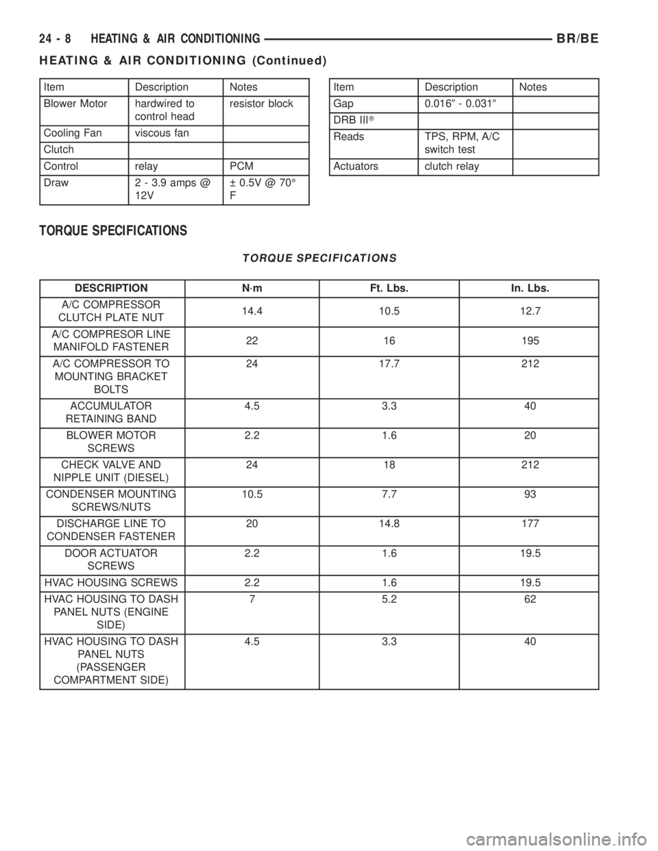
TORQUE SPECIFICATIONS
TORQUE SPECIFICATIONS
DESCRIPTION N´m Ft. Lbs. In. Lbs.
A/C COMPRESSOR
CLUTCH PLATE NUT14.4 10.5 12.7
A/C COMPRESOR LINE
MANIFOLD FASTENER22 16 195
A/C COMPRESSOR TO
MOUNTING BRACKET
BOLTS24 17.7 212
ACCUMULATOR
RETAINING BAND4.5 3.3 40
BLOWER MOTOR
SCREWS2.2 1.6 20
CHECK VALVE AND
NIPPLE UNIT (DIESEL)24 18 212
CONDENSER MOUNTING
SCREWS/NUTS10.5 7.7 93
DISCHARGE LINE TO
CONDENSER FASTENER20 14.8 177
DOOR ACTUATOR
SCREWS2.2 1.6 19.5
HVAC HOUSING SCREWS 2.2 1.6 19.5
HVAC HOUSING TO DASH
PANEL NUTS (ENGINE
SIDE)7 5.2 62
HVAC HOUSING TO DASH
PANEL NUTS
(PASSENGER
COMPARTMENT SIDE)4.5 3.3 40
24 - 8 HEATING & AIR CONDITIONINGBR/BE
HEATING & AIR CONDITIONING (Continued)