Page 1918 of 2255
TRANSFER CASE - NV241HD
TABLE OF CONTENTS
page page
TRANSFER CASE - NV241HD
DESCRIPTION........................465
OPERATION..........................467
DIAGNOSIS AND TESTING - TRANSFER
CASE..............................467
REMOVAL............................469
DISASSEMBLY........................469
CLEANING...........................476
INSPECTION.........................476
ASSEMBLY...........................480
INSTALLATION........................494
SPECIFICATIONS
TRANSFER CASE....................495
SPECIAL TOOLS
TRANSFER CASE - NV241HD...........495EXTENSION HOUSING BUSHING AND SEAL
REMOVAL............................497
INSTALLATION........................497
FLUID
STANDARD PROCEDURE - FLUID DRAIN/
REFILL............................497
FRONT OUTPUT SHAFT SEAL
REMOVAL............................498
INSTALLATION........................498
SHIFT LEVER
REMOVAL............................499
INSTALLATION........................500
ADJUSTMENTS
ADJUSTMENT - SHIFT LEVER..........500
TRANSFER CASE - NV241HD
DESCRIPTION
The NV241HD is a part-time transfer case with a
low-range gear system. The transfer case provides
three operating ranges plus a NEUTRAL position.
The low range position provides a gear reduction
ratio of 2.72:1 for increased low speed torque capabil-
ity. Operating ranges are: 2H, 4H, and 4LO.
The synchronizer mechanism consists of a brass
stop ring, synchronizer hub, and the sliding clutch
(Fig. 1). The synchronizer components allow the
transfer case to be shifted between the 2H and 4H
operating ranges while the vehicle is in motion.The gear cases, retainer and extension are all of
aluminum. Drive sprockets and an interconnecting
drive chain are used to transmit engine torque to the
front/rear propeller shafts. The mainshaft, input gear
and front output shaft are supported by ball and nee-
dle bearings.
PTO CAPABILITY
The NV241HD transfer case has power take-off
capability. A PTO gear permanently attached to the
planetary carrier, and a removable PTO cover are
provided for this purpose.
BR/BETRANSFER CASE - NV241HD 21 - 465
Page 1920 of 2255
IDENTIFICATION
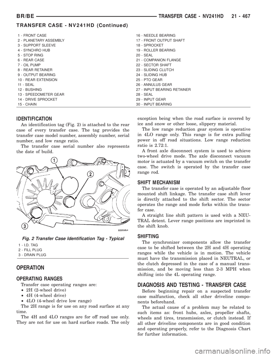
An identification tag (Fig. 2) is attached to the rear
case of every transfer case. The tag provides the
transfer case model number, assembly number, serial
number, and low range ratio.
The transfer case serial number also represents
the date of build.
OPERATION
OPERATING RANGES
Transfer case operating ranges are:
²2H (2-wheel drive)
²4H (4-wheel drive)
²4LO (4-wheel drive low range)
The 2H range is for use on any road surface at any
time.
The 4H and 4LO ranges are for off road use only.
They are not for use on hard surface roads. The onlyexception being when the road surface is covered by
ice and snow or other loose, slippery material.
The low range reduction gear system is operative
in 4LO range only. This range is for extra pulling
power in off road situations. Low range reduction
ratio is 2.72:1.
A front axle disconnect system is used to achieve
two-wheel drive mode. The axle disconnect vacuum
motor is actuated by a vacuum switch on the transfer
case. The switch is operated by the transfer case
range rod.
SHIFT MECHANISM
The transfer case is operated by an adjustable floor
mounted shift linkage. The transfer case shift lever
is directly attached to the shift sector. The sector
operates the range and mode forks within the trans-
fer case.
A straight line shift pattern is used with a NEU-
TRAL detent. Lever range positions are imprinted in
the shift knob.
SHIFTING
The synchronizer components allow the transfer
case to be shifted between the 2H and 4H operating
ranges while the vehicle is in motion. The vehicle
must have the transmission placed in NEUTRAL, or
the clutch depressed in the case of a manual trans-
mission, and be moving less than 2-3 MPH when
shifting into the 4L operating range.
DIAGNOSIS AND TESTING - TRANSFER CASE
Before beginning repair on a suspected transfer
case malfunction, check all other driveline compo-
nents beforehand.
The actual cause of a problem may be related to
such items as: front hubs, axles, propeller shafts,
wheels and tires, transmission, or clutch instead. If
all other driveline components are in good condition
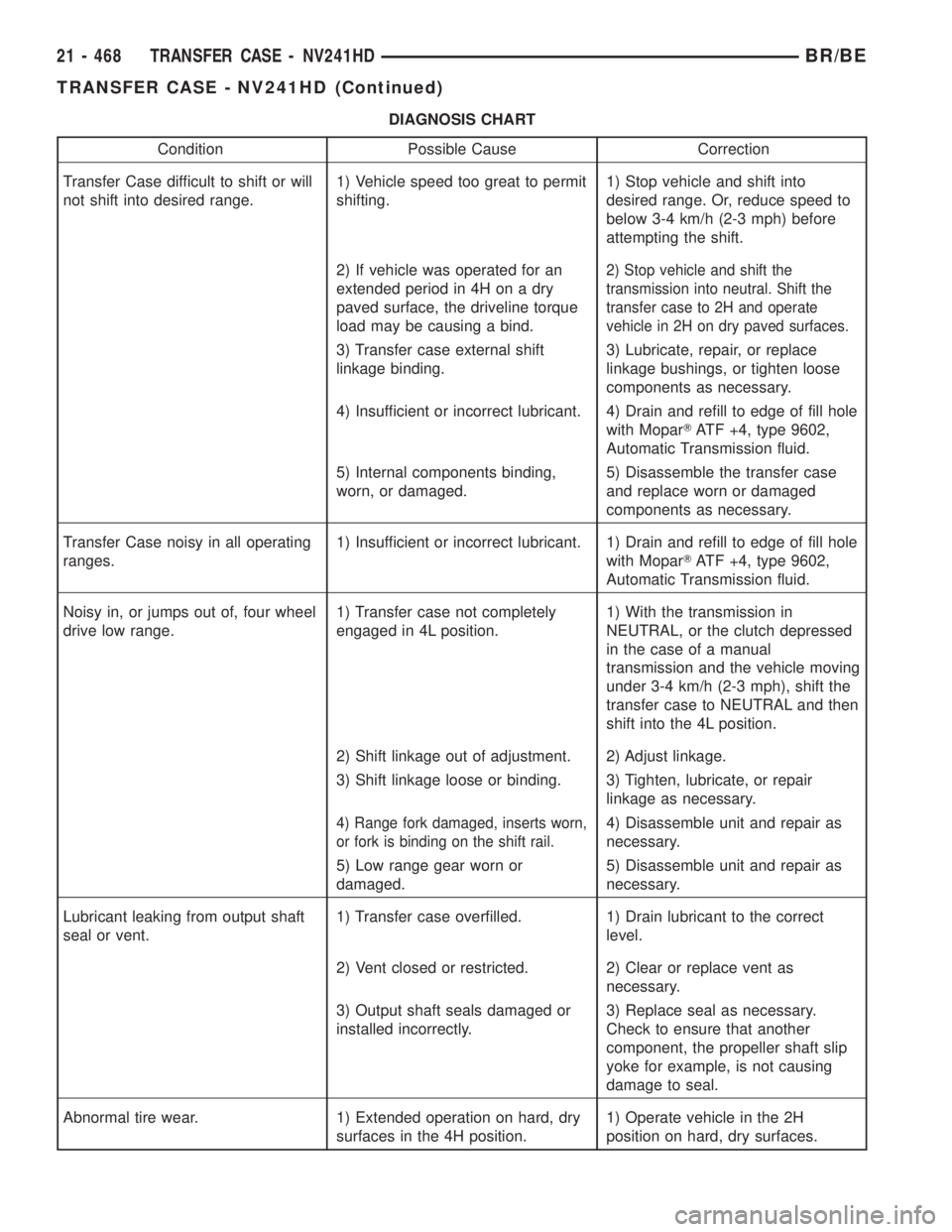
and operating properly, refer to the Diagnosis Chart
for further information.
1 - FRONT CASE 16 - NEEDLE BEARING
2 - PLANETARY ASSEMBLY 17 - FRONT OUTPUT SHAFT
3 - SUPPORT SLEEVE 18 - SPROCKET
4 - SYNCHRO HUB 19 - ROLLER BEARING
5 - STOP RING 20 - SEAL
6 - REAR CASE 21 - COMPANION FLANGE
7 - OIL PUMP 22 - SECTOR SHAFT
8 - REAR RETAINER 23 - SLIDING CLUTCH
9 - OUTPUT BEARING 24 - SLIDING HUB
10 - REAR EXTENSION 25 - PTO GEAR
11 - SEAL 26 - ANNULUS GEAR
12 - BUSHING 27 - INPUT BEARING RETAINER
13 - SPEEDOMETER GEAR 28 - SEAL
14 - DRIVE SPROCKET 29 - INPUT GEAR
15 - CHAIN 30 - INPUT BEARING
Fig. 2 Transfer Case Identification Tag - Typical
1 - I.D. TAG
2 - FILL PLUG
3 - DRAIN PLUG
BR/BETRANSFER CASE - NV241HD 21 - 467
TRANSFER CASE - NV241HD (Continued)
Page 1921 of 2255
DIAGNOSIS CHART
Condition Possible Cause Correction
Transfer Case difficult to shift or will
not shift into desired range.1) Vehicle speed too great to permit
shifting.1) Stop vehicle and shift into
desired range. Or, reduce speed to
below 3-4 km/h (2-3 mph) before
attempting the shift.
2) If vehicle was operated for an
extended period in 4H on a dry
paved surface, the driveline torque
load may be causing a bind.
2) Stop vehicle and shift the
transmission into neutral. Shift the
transfer case to 2H and operate
vehicle in 2H on dry paved surfaces.
3) Transfer case external shift
linkage binding.3) Lubricate, repair, or replace
linkage bushings, or tighten loose
components as necessary.
4) Insufficient or incorrect lubricant. 4) Drain and refill to edge of fill hole
with MoparTATF +4, type 9602,
Automatic Transmission fluid.
5) Internal components binding,
worn, or damaged.5) Disassemble the transfer case
and replace worn or damaged
components as necessary.
Transfer Case noisy in all operating
ranges.1) Insufficient or incorrect lubricant. 1) Drain and refill to edge of fill hole
with MoparTATF +4, type 9602,
Automatic Transmission fluid.
Noisy in, or jumps out of, four wheel
drive low range.1) Transfer case not completely
engaged in 4L position.1) With the transmission in
NEUTRAL, or the clutch depressed
in the case of a manual
transmission and the vehicle moving
under 3-4 km/h (2-3 mph), shift the
transfer case to NEUTRAL and then
shift into the 4L position.
2) Shift linkage out of adjustment. 2) Adjust linkage.
3) Shift linkage loose or binding. 3) Tighten, lubricate, or repair
linkage as necessary.
4) Range fork damaged, inserts worn,
or fork is binding on the shift rail.4) Disassemble unit and repair as
necessary.
5) Low range gear worn or
damaged.5) Disassemble unit and repair as
necessary.
Lubricant leaking from output shaft
seal or vent.1) Transfer case overfilled. 1) Drain lubricant to the correct
level.
2) Vent closed or restricted. 2) Clear or replace vent as
necessary.
3) Output shaft seals damaged or
installed incorrectly.3) Replace seal as necessary.
Check to ensure that another
component, the propeller shaft slip
yoke for example, is not causing
damage to seal.
Abnormal tire wear. 1) Extended operation on hard, dry
surfaces in the 4H position.1) Operate vehicle in the 2H
position on hard, dry surfaces.
21 - 468 TRANSFER CASE - NV241HDBR/BE
TRANSFER CASE - NV241HD (Continued)
Page 1925 of 2255
(4) Remove poppet plunger with magnet (Fig. 15).
(5) Remove front output shaft from bearing in case
(Fig. 16).(6) Pull mainshaft assembly out of input gear, slid-
ing clutch and case (Fig. 17).
(7) Remove mode fork, sliding clutch and shift rail
as assembly (Fig. 18). Note which way clutch fits in
fork (long side of clutch goes to front).
Fig. 15 Poppet Plunger Removal
1 - MAGNET
2 - POPPET PLUNGER
Fig. 16 Front Output Shaft Removal
1 - BALL BEARING
2 - FRONT OUTPUT SHAFT
Fig. 17 Mainshaft Assembly Removal
1 - SLIDING CLUTCH
2 - MODE FORK
3 - MAINSHAFT ASSEMBLY
Fig. 18 Mode Fork, Shift Rail And Sliding Clutch
Removal
1 - MODE FORK
2 - SHIFT RAIL
3 - SLIDING CLUTCH
21 - 472 TRANSFER CASE - NV241HDBR/BE
TRANSFER CASE - NV241HD (Continued)
Page 1931 of 2255
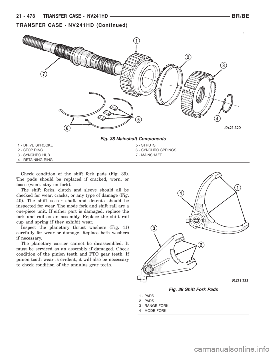
Check condition of the shift fork pads (Fig. 39).
The pads should be replaced if cracked, worn, or
loose (won't stay on fork).
The shift forks, clutch and sleeve should all be
checked for wear, cracks, or any type of damage (Fig.
40). The shift sector shaft and detents should be
inspected for wear. The mode fork and shift rail are a
one-piece unit. If either part is damaged, replace the
fork and rail as an assembly. Replace the shift rail
cup and spring if they exhibit wear.
Inspect the planetary thrust washers (Fig. 41)
carefully for wear or damage. Replace both washers
if necessary.
The planetary carrier cannot be disassembled. It
must be serviced as an assembly if damaged. Check
condition of the pinion teeth and PTO gear teeth. If
pinion tooth wear is evident, it will also be necessary
to check condition of the annulus gear teeth.
Fig. 38 Mainshaft Components
1 - DRIVE SPROCKET 5 - STRUTS
2 - STOP RING 6 - SYNCHRO SPRINGS
3 - SYNCHRO HUB 7 - MAINSHAFT
4 - RETAINING RING
Fig. 39 Shift Fork Pads
1-PADS
2-PADS
3 - RANGE FORK
4 - MODE FORK
21 - 478 TRANSFER CASE - NV241HDBR/BE
TRANSFER CASE - NV241HD (Continued)
Page 1932 of 2255
Fig. 40 Shift Fork Components
1 - SUPPORT SLEEVE 5 - MODE FORK AND SHIFT RAIL
2 - RANGE FORK 6 - SPRING
3 - SHIFT SECTOR 7 - CUP
4 - POPPET PLUNGER, SPRING, SCREW 8 - SLIDING CLUTCH
Fig. 41 Planetary And Input Gear Components
1 - LOCK RING 6 - RETAINING RING
2 - THRUST WASHERS 7 - SUPPORT SLEEVE
3 - PLANETARY CARRIER 8 - INPUT GEAR
4 - PTO GEAR 9 - RETAINING RING
5 - BEARING
BR/BETRANSFER CASE - NV241HD 21 - 479
TRANSFER CASE - NV241HD (Continued)
Page 1939 of 2255
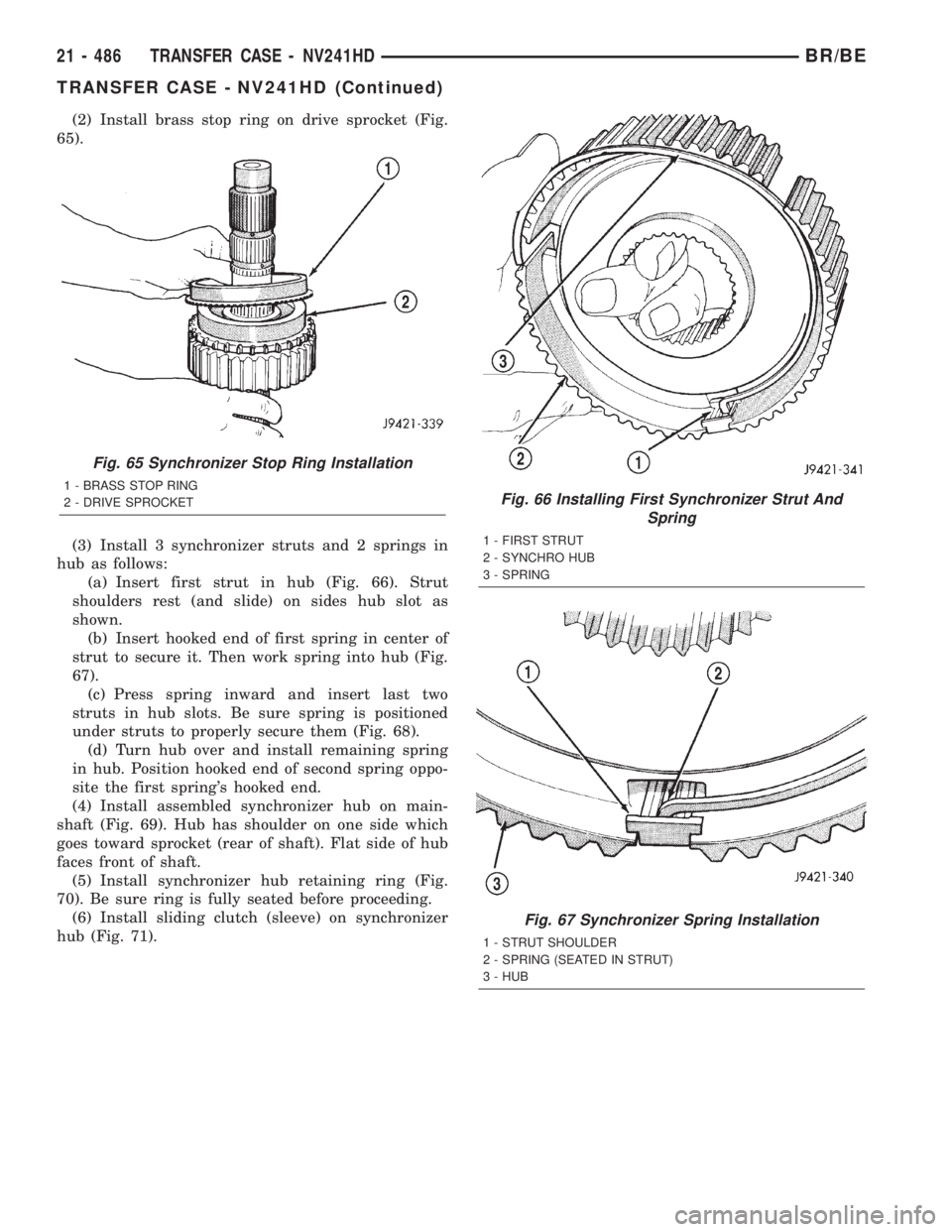
(2) Install brass stop ring on drive sprocket (Fig.
65).
(3) Install 3 synchronizer struts and 2 springs in
hub as follows:
(a) Insert first strut in hub (Fig. 66). Strut
shoulders rest (and slide) on sides hub slot as
shown.
(b) Insert hooked end of first spring in center of
strut to secure it. Then work spring into hub (Fig.
67).
(c) Press spring inward and insert last two
struts in hub slots. Be sure spring is positioned
under struts to properly secure them (Fig. 68).
(d) Turn hub over and install remaining spring
in hub. Position hooked end of second spring oppo-
site the first spring's hooked end.
(4) Install assembled synchronizer hub on main-
shaft (Fig. 69). Hub has shoulder on one side which
goes toward sprocket (rear of shaft). Flat side of hub
faces front of shaft.
(5) Install synchronizer hub retaining ring (Fig.
70). Be sure ring is fully seated before proceeding.
(6) Install sliding clutch (sleeve) on synchronizer
hub (Fig. 71).
Fig. 65 Synchronizer Stop Ring Installation
1 - BRASS STOP RING
2 - DRIVE SPROCKETFig. 66 Installing First Synchronizer Strut And
Spring
1 - FIRST STRUT
2 - SYNCHRO HUB
3 - SPRING
Fig. 67 Synchronizer Spring Installation
1 - STRUT SHOULDER
2 - SPRING (SEATED IN STRUT)
3 - HUB
21 - 486 TRANSFER CASE - NV241HDBR/BE
TRANSFER CASE - NV241HD (Continued)
Page 1940 of 2255
Fig. 68 Correct Position Of Struts And Springs
1 - STRUTS
2 - SPRING
Fig. 69 Synchronizer Hub Installation
1 - SYNCHRO HUB (SHOULDER SIDE DOWN)
2 - STOP RING AND SPROCKET
Fig. 70 Synchronizer Hub Retaining Ring
Installation
1 - SNAP-RING PLIERS
2 - SYNCHRO HUB
3 - HUB RETAINING RING
Fig. 71 Sliding Clutch Installation
1 - SLIDING CLUTCH
2 - SYNCHRO HUB
BR/BETRANSFER CASE - NV241HD 21 - 487
TRANSFER CASE - NV241HD (Continued)