2002 DODGE RAM clutch
[x] Cancel search: clutchPage 1863 of 2255
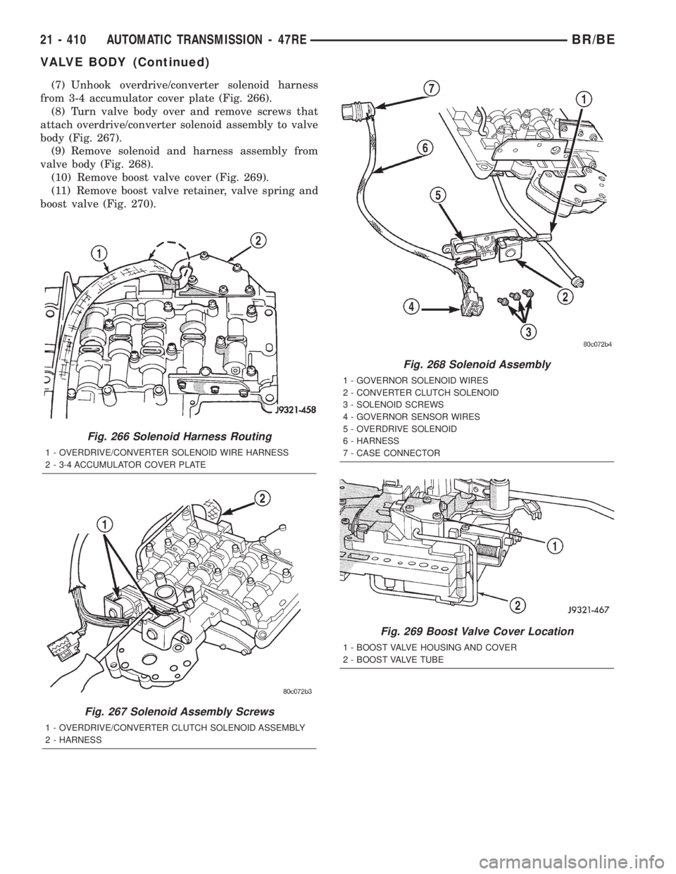
(7) Unhook overdrive/converter solenoid harness
from 3-4 accumulator cover plate (Fig. 266).
(8) Turn valve body over and remove screws that
attach overdrive/converter solenoid assembly to valve
body (Fig. 267).
(9) Remove solenoid and harness assembly from
valve body (Fig. 268).
(10) Remove boost valve cover (Fig. 269).
(11) Remove boost valve retainer, valve spring and
boost valve (Fig. 270).
Fig. 266 Solenoid Harness Routing
1 - OVERDRIVE/CONVERTER SOLENOID WIRE HARNESS
2 - 3-4 ACCUMULATOR COVER PLATE
Fig. 267 Solenoid Assembly Screws
1 - OVERDRIVE/CONVERTER CLUTCH SOLENOID ASSEMBLY
2 - HARNESS
Fig. 268 Solenoid Assembly
1 - GOVERNOR SOLENOID WIRES
2 - CONVERTER CLUTCH SOLENOID
3 - SOLENOID SCREWS
4 - GOVERNOR SENSOR WIRES
5 - OVERDRIVE SOLENOID
6 - HARNESS
7 - CASE CONNECTOR
Fig. 269 Boost Valve Cover Location
1 - BOOST VALVE HOUSING AND COVER
2 - BOOST VALVE TUBE
21 - 410 AUTOMATIC TRANSMISSION - 47REBR/BE
VALVE BODY (Continued)
Page 1867 of 2255
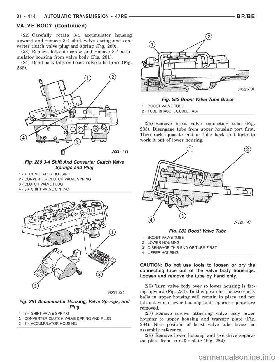
(22) Carefully rotate 3-4 accumulator housing
upward and remove 3-4 shift valve spring and con-
verter clutch valve plug and spring (Fig. 280).
(23) Remove left-side screw and remove 3-4 accu-
mulator housing from valve body (Fig. 281).
(24) Bend back tabs on boost valve tube brace (Fig.
282).
(25) Remove boost valve connecting tube (Fig.
283). Disengage tube from upper housing port first.
Then rock opposite end of tube back and forth to
work it out of lower housing.
CAUTION: Do not use tools to loosen or pry the
connecting tube out of the valve body housings.
Loosen and remove the tube by hand only.
(26) Turn valve body over so lower housing is fac-
ing upward (Fig. 284). In this position, the two check
balls in upper housing will remain in place and not
fall out when lower housing and separator plate are
removed.
(27) Remove screws attaching valve body lower
housing to upper housing and transfer plate (Fig.
284). Note position of boost valve tube brace for
assembly reference.
(28) Remove lower housing and overdrive separa-
tor plate from transfer plate (Fig. 284).
Fig. 280 3-4 Shift And Converter Clutch Valve
Springs and Plug
1 - ACCUMULATOR HOUSING
2 - CONVERTER CLUTCH VALVE SPRING
3 - CLUTCH VALVE PLUG
4 - 3-4 SHIFT VALVE SPRING
Fig. 281 Accumulator Housing, Valve Springs, and
Plug
1 - 3-4 SHIFT VALVE SPRING
2 - CONVERTER CLUTCH VALVE SPRING AND PLUG
3 - 3-4 ACCUMULATOR HOUSING
Fig. 282 Boost Valve Tube Brace
1 - BOOST VALVE TUBE
2 - TUBE BRACE (DOUBLE TAB)
Fig. 283 Boost Valve Tube
1 - BOOST VALVE TUBE
2 - LOWER HOUSING
3 - DISENGAGE THIS END OF TUBE FIRST
4 - UPPER HOUSING
21 - 414 AUTOMATIC TRANSMISSION - 47REBR/BE
VALVE BODY (Continued)
Page 1868 of 2255
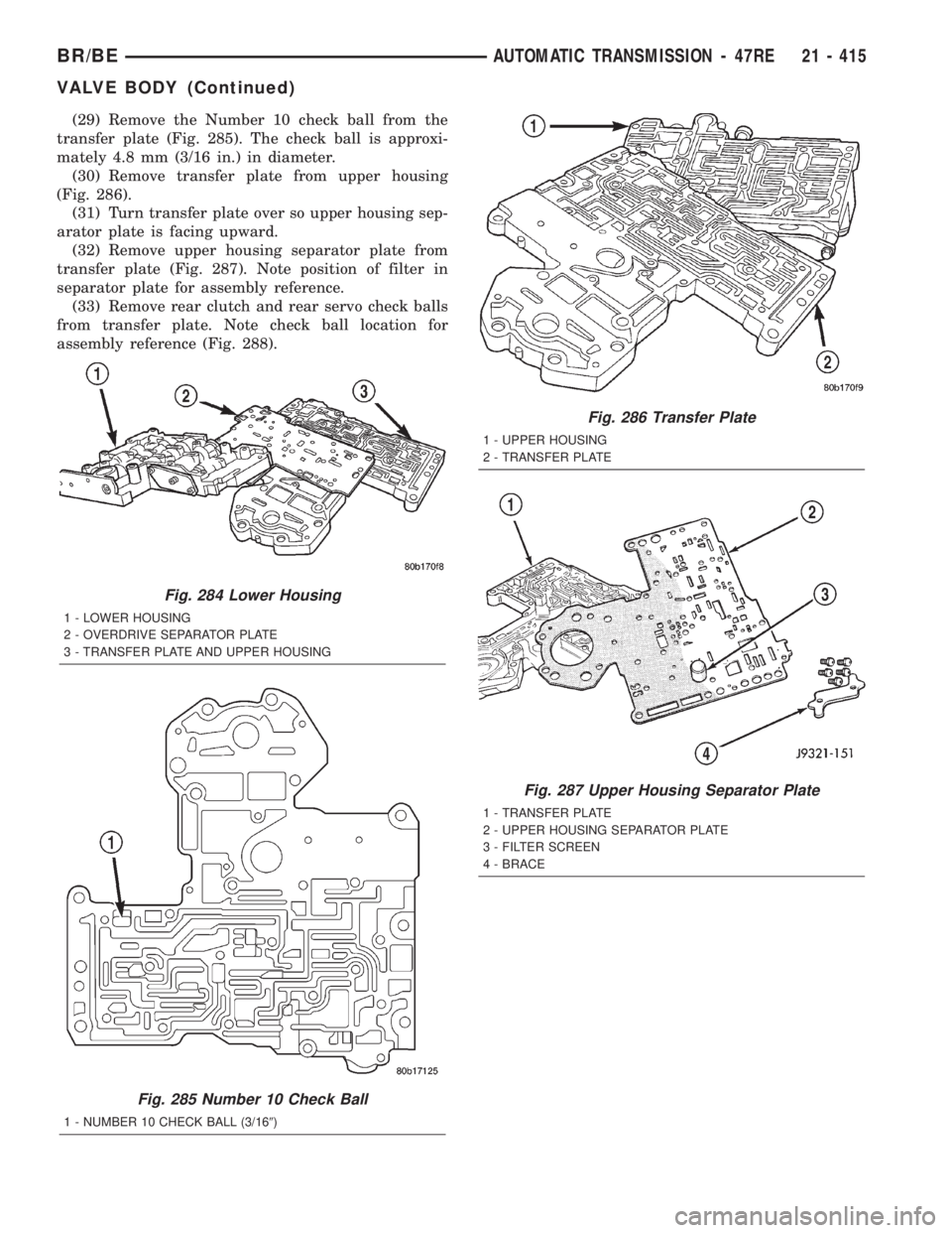
(29) Remove the Number 10 check ball from the
transfer plate (Fig. 285). The check ball is approxi-
mately 4.8 mm (3/16 in.) in diameter.
(30) Remove transfer plate from upper housing
(Fig. 286).
(31) Turn transfer plate over so upper housing sep-
arator plate is facing upward.
(32) Remove upper housing separator plate from
transfer plate (Fig. 287). Note position of filter in
separator plate for assembly reference.
(33) Remove rear clutch and rear servo check balls
from transfer plate. Note check ball location for
assembly reference (Fig. 288).
Fig. 284 Lower Housing
1 - LOWER HOUSING
2 - OVERDRIVE SEPARATOR PLATE
3 - TRANSFER PLATE AND UPPER HOUSING
Fig. 285 Number 10 Check Ball
1 - NUMBER 10 CHECK BALL (3/169)
Fig. 286 Transfer Plate
1 - UPPER HOUSING
2 - TRANSFER PLATE
Fig. 287 Upper Housing Separator Plate
1 - TRANSFER PLATE
2 - UPPER HOUSING SEPARATOR PLATE
3 - FILTER SCREEN
4 - BRACE
BR/BEAUTOMATIC TRANSMISSION - 47RE 21 - 415
VALVE BODY (Continued)
Page 1869 of 2255
VALVE BODY UPPER HOUSING
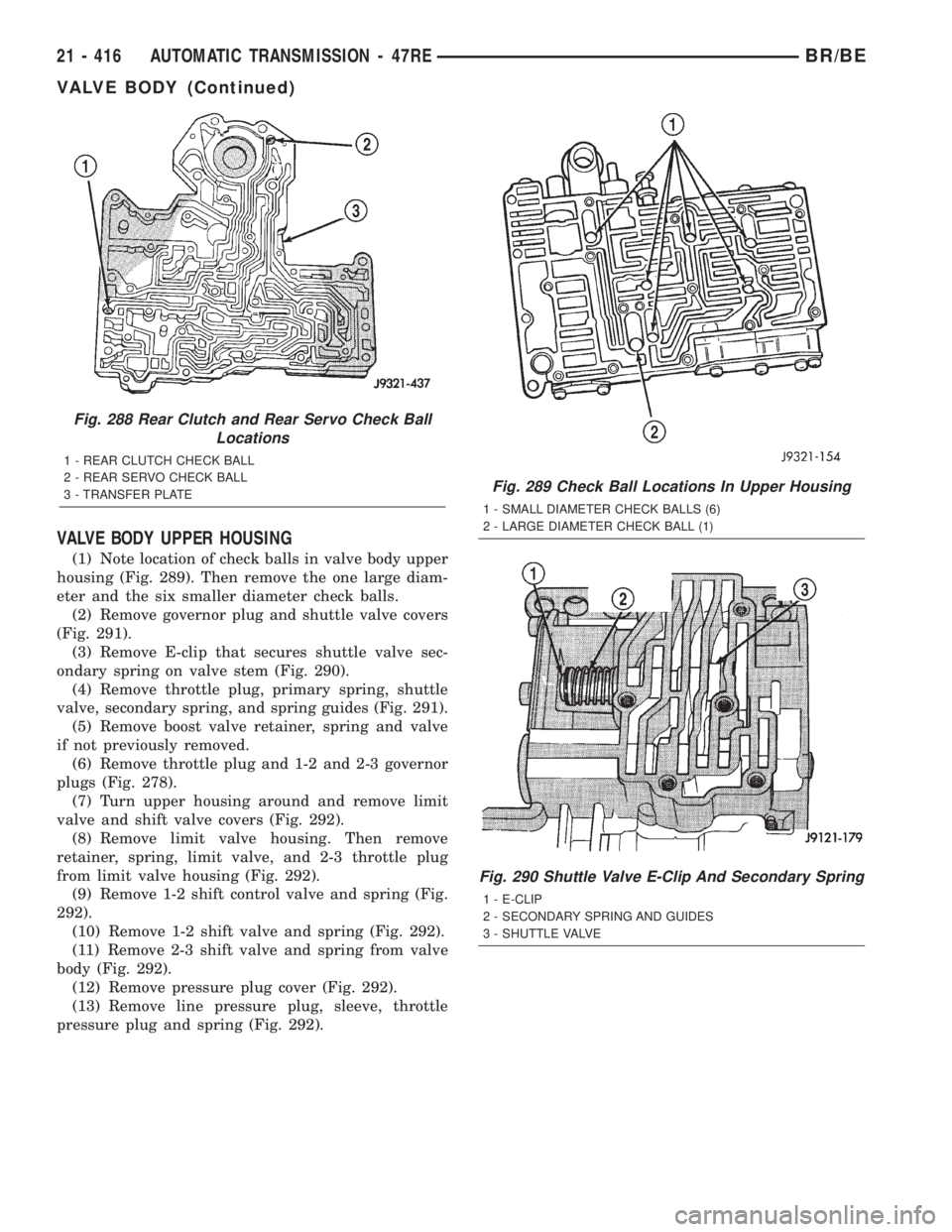
(1) Note location of check balls in valve body upper
housing (Fig. 289). Then remove the one large diam-
eter and the six smaller diameter check balls.
(2) Remove governor plug and shuttle valve covers
(Fig. 291).
(3) Remove E-clip that secures shuttle valve sec-
ondary spring on valve stem (Fig. 290).
(4) Remove throttle plug, primary spring, shuttle
valve, secondary spring, and spring guides (Fig. 291).
(5) Remove boost valve retainer, spring and valve
if not previously removed.
(6) Remove throttle plug and 1-2 and 2-3 governor
plugs (Fig. 278).
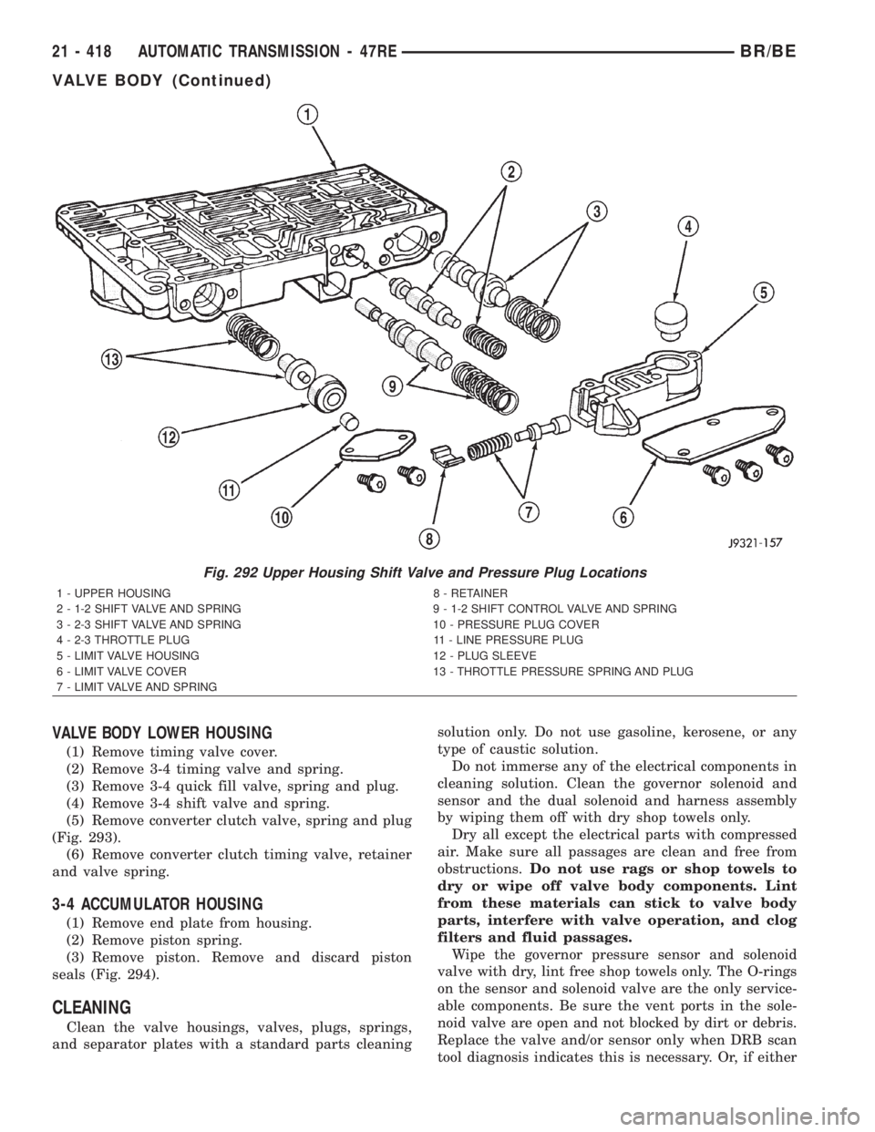
(7) Turn upper housing around and remove limit
valve and shift valve covers (Fig. 292).
(8) Remove limit valve housing. Then remove
retainer, spring, limit valve, and 2-3 throttle plug
from limit valve housing (Fig. 292).
(9) Remove 1-2 shift control valve and spring (Fig.
292).
(10) Remove 1-2 shift valve and spring (Fig. 292).
(11) Remove 2-3 shift valve and spring from valve
body (Fig. 292).
(12) Remove pressure plug cover (Fig. 292).
(13) Remove line pressure plug, sleeve, throttle
pressure plug and spring (Fig. 292).
Fig. 288 Rear Clutch and Rear Servo Check Ball
Locations
1 - REAR CLUTCH CHECK BALL
2 - REAR SERVO CHECK BALL
3 - TRANSFER PLATE
Fig. 289 Check Ball Locations In Upper Housing
1 - SMALL DIAMETER CHECK BALLS (6)
2 - LARGE DIAMETER CHECK BALL (1)
Fig. 290 Shuttle Valve E-Clip And Secondary Spring
1 - E-CLIP
2 - SECONDARY SPRING AND GUIDES
3 - SHUTTLE VALVE
21 - 416 AUTOMATIC TRANSMISSION - 47REBR/BE
VALVE BODY (Continued)
Page 1871 of 2255
VALVE BODY LOWER HOUSING
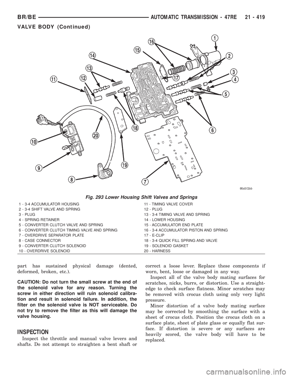
(1) Remove timing valve cover.
(2) Remove 3-4 timing valve and spring.
(3) Remove 3-4 quick fill valve, spring and plug.
(4) Remove 3-4 shift valve and spring.
(5) Remove converter clutch valve, spring and plug
(Fig. 293).
(6) Remove converter clutch timing valve, retainer
and valve spring.
3-4 ACCUMULATOR HOUSING
(1) Remove end plate from housing.
(2) Remove piston spring.
(3) Remove piston. Remove and discard piston
seals (Fig. 294).
CLEANING
Clean the valve housings, valves, plugs, springs,
and separator plates with a standard parts cleaningsolution only. Do not use gasoline, kerosene, or any
type of caustic solution.
Do not immerse any of the electrical components in
cleaning solution. Clean the governor solenoid and
sensor and the dual solenoid and harness assembly
by wiping them off with dry shop towels only.
Dry all except the electrical parts with compressed
air. Make sure all passages are clean and free from
obstructions.Do not use rags or shop towels to
dry or wipe off valve body components. Lint
from these materials can stick to valve body
parts, interfere with valve operation, and clog
filters and fluid passages.
Wipe the governor pressure sensor and solenoid
valve with dry, lint free shop towels only. The O-rings
on the sensor and solenoid valve are the only service-
able components. Be sure the vent ports in the sole-
noid valve are open and not blocked by dirt or debris.
Replace the valve and/or sensor only when DRB scan
tool diagnosis indicates this is necessary. Or, if either
Fig. 292 Upper Housing Shift Valve and Pressure Plug Locations
1 - UPPER HOUSING 8 - RETAINER
2 - 1-2 SHIFT VALVE AND SPRING 9 - 1-2 SHIFT CONTROL VALVE AND SPRING
3 - 2-3 SHIFT VALVE AND SPRING 10 - PRESSURE PLUG COVER
4 - 2-3 THROTTLE PLUG 11 - LINE PRESSURE PLUG
5 - LIMIT VALVE HOUSING 12 - PLUG SLEEVE
6 - LIMIT VALVE COVER 13 - THROTTLE PRESSURE SPRING AND PLUG
7 - LIMIT VALVE AND SPRING
21 - 418 AUTOMATIC TRANSMISSION - 47REBR/BE
VALVE BODY (Continued)
Page 1872 of 2255
part has sustained physical damage (dented,
deformed, broken, etc.).
CAUTION: Do not turn the small screw at the end of
the solenoid valve for any reason. Turning the
screw in either direction will ruin solenoid calibra-
tion and result in solenoid failure. In addition, the
filter on the solenoid valve is NOT serviceable. Do
not try to remove the filter as this will damage the
valve housing.
INSPECTION
Inspect the throttle and manual valve levers and
shafts. Do not attempt to straighten a bent shaft orcorrect a loose lever. Replace these components if
worn, bent, loose or damaged in any way.
Inspect all of the valve body mating surfaces for
scratches, nicks, burrs, or distortion. Use a straight-
edge to check surface flatness. Minor scratches may
be removed with crocus cloth using only very light
pressure.
Minor distortion of a valve body mating surface
may be corrected by smoothing the surface with a
sheet of crocus cloth. Position the crocus cloth on a
surface plate, sheet of plate glass or equally flat sur-
face. If distortion is severe or any surfaces are
heavily scored, the valve body will have to be
replaced.
Fig. 293 Lower Housing Shift Valves and Springs
1 - 3-4 ACCUMULATOR HOUSING 11 - TIMING VALVE COVER
2 - 3-4 SHIFT VALVE AND SPRING 12 - PLUG
3 - PLUG 13 - 3-4 TIMING VALVE AND SPRING
4 - SPRING RETAINER 14 - LOWER HOUSING
5 - CONVERTER CLUTCH VALVE AND SPRING 15 - ACCUMULATOR END PLATE
6 - CONVERTER CLUTCH TIMING VALVE AND SPRING 16 - 3-4 ACCUMULATOR PISTON AND SPRING
7 - OVERDRIVE SEPARATOR PLATE 17 - E-CLIP
8 - CASE CONNECTOR 18 - 3-4 QUICK FILL SPRING AND VALVE
9 - CONVERTER CLUTCH SOLENOID 19 - SOLENOID GASKET
10 - OVERDRIVE SOLENOID 20 - HARNESS
BR/BEAUTOMATIC TRANSMISSION - 47RE 21 - 419
VALVE BODY (Continued)
Page 1874 of 2255
3-4 ACCUMULATOR
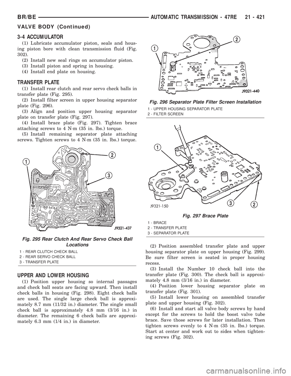
(1) Lubricate accumulator piston, seals and hous-
ing piston bore with clean transmission fluid (Fig.
302).
(2) Install new seal rings on accumulator piston.
(3) Install piston and spring in housing.
(4) Install end plate on housing.
TRANSFER PLATE
(1) Install rear clutch and rear servo check balls in
transfer plate (Fig. 295).
(2) Install filter screen in upper housing separator
plate (Fig. 296).
(3) Align and position upper housing separator
plate on transfer plate (Fig. 297).
(4) Install brace plate (Fig. 297). Tighten brace
attaching screws to 4 N´m (35 in. lbs.) torque.
(5) Install remaining separator plate attaching
screws. Tighten screws to 4 N´m (35 in. lbs.) torque.
UPPER AND LOWER HOUSING
(1) Position upper housing so internal passages
and check ball seats are facing upward. Then install
check balls in housing (Fig. 298). Eight check balls
are used. The single large check ball is approxi-
mately 8.7 mm (11/32 in.) diameter. The single small
check ball is approximately 4.8 mm (3/16 in.) in
diameter. The remaining 6 check balls are approxi-
mately 6.3 mm (1/4 in.) in diameter.(2) Position assembled transfer plate and upper
housing separator plate on upper housing (Fig. 299).
Be sure filter screen is seated in proper housing
recess.
(3) Install the Number 10 check ball into the
transfer plate (Fig. 300). The check ball is approxi-
mately 4.8 mm (3/16 in.) in diameter.
(4) Position lower housing separator plate on
transfer plate (Fig. 301).
(5) Install lower housing on assembled transfer
plate and upper housing (Fig. 302).
(6) Install and start all valve body screws by hand
except for the screws to hold the boost valve tube
brace. Save those screws for later installation. Then
tighten screws evenly to 4 N´m (35 in. lbs.) torque.
Start at center and work out to sides when tighten-
ing screws (Fig. 302).
Fig. 295 Rear Clutch And Rear Servo Check Ball
Locations
1 - REAR CLUTCH CHECK BALL
2 - REAR SERVO CHECK BALL
3 - TRANSFER PLATE
Fig. 296 Separator Plate Filter Screen Installation
1 - UPPER HOUSING SEPARATOR PLATE
2 - FILTER SCREEN
Fig. 297 Brace Plate
1 - BRACE
2 - TRANSFER PLATE
3 - SEPARATOR PLATE
BR/BEAUTOMATIC TRANSMISSION - 47RE 21 - 421
VALVE BODY (Continued)
Page 1879 of 2255
3-4 ACCUMULATOR
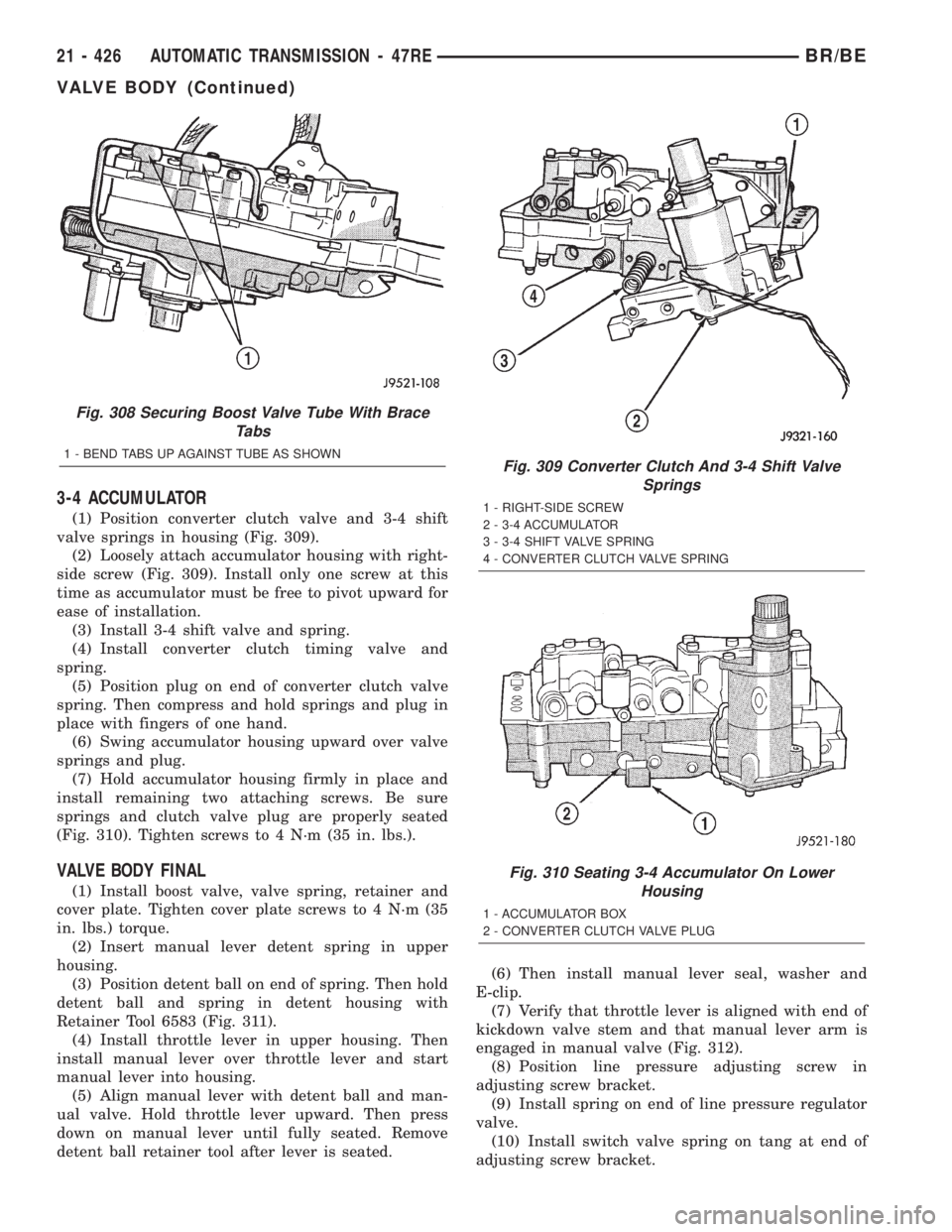
(1) Position converter clutch valve and 3-4 shift
valve springs in housing (Fig. 309).
(2) Loosely attach accumulator housing with right-
side screw (Fig. 309). Install only one screw at this
time as accumulator must be free to pivot upward for
ease of installation.
(3) Install 3-4 shift valve and spring.
(4) Install converter clutch timing valve and
spring.
(5) Position plug on end of converter clutch valve
spring. Then compress and hold springs and plug in
place with fingers of one hand.
(6) Swing accumulator housing upward over valve
springs and plug.
(7) Hold accumulator housing firmly in place and
install remaining two attaching screws. Be sure
springs and clutch valve plug are properly seated
(Fig. 310). Tighten screws to 4 N´m (35 in. lbs.).
VALVE BODY FINAL
(1) Install boost valve, valve spring, retainer and
cover plate. Tighten cover plate screws to 4 N´m (35
in. lbs.) torque.
(2) Insert manual lever detent spring in upper
housing.
(3) Position detent ball on end of spring. Then hold
detent ball and spring in detent housing with
Retainer Tool 6583 (Fig. 311).
(4) Install throttle lever in upper housing. Then
install manual lever over throttle lever and start
manual lever into housing.
(5) Align manual lever with detent ball and man-
ual valve. Hold throttle lever upward. Then press
down on manual lever until fully seated. Remove
detent ball retainer tool after lever is seated.(6) Then install manual lever seal, washer and
E-clip.
(7) Verify that throttle lever is aligned with end of
kickdown valve stem and that manual lever arm is
engaged in manual valve (Fig. 312).
(8) Position line pressure adjusting screw in
adjusting screw bracket.
(9) Install spring on end of line pressure regulator
valve.
(10) Install switch valve spring on tang at end of
adjusting screw bracket.
Fig. 308 Securing Boost Valve Tube With Brace
Tabs
1 - BEND TABS UP AGAINST TUBE AS SHOWNFig. 309 Converter Clutch And 3-4 Shift Valve
Springs
1 - RIGHT-SIDE SCREW
2 - 3-4 ACCUMULATOR
3 - 3-4 SHIFT VALVE SPRING
4 - CONVERTER CLUTCH VALVE SPRING
Fig. 310 Seating 3-4 Accumulator On Lower
Housing
1 - ACCUMULATOR BOX
2 - CONVERTER CLUTCH VALVE PLUG
21 - 426 AUTOMATIC TRANSMISSION - 47REBR/BE
VALVE BODY (Continued)