2002 DODGE RAM clutch
[x] Cancel search: clutchPage 2180 of 2255
EMISSIONS CONTROL
TABLE OF CONTENTS
page page
EMISSIONS CONTROL
DESCRIPTION
DESCRIPTION - DIESEL.................1
DESCRIPTION - STATE DISPLAY TEST
MODE...............................1
DESCRIPTION - CIRCUIT ACTUATION TEST
MODE...............................2
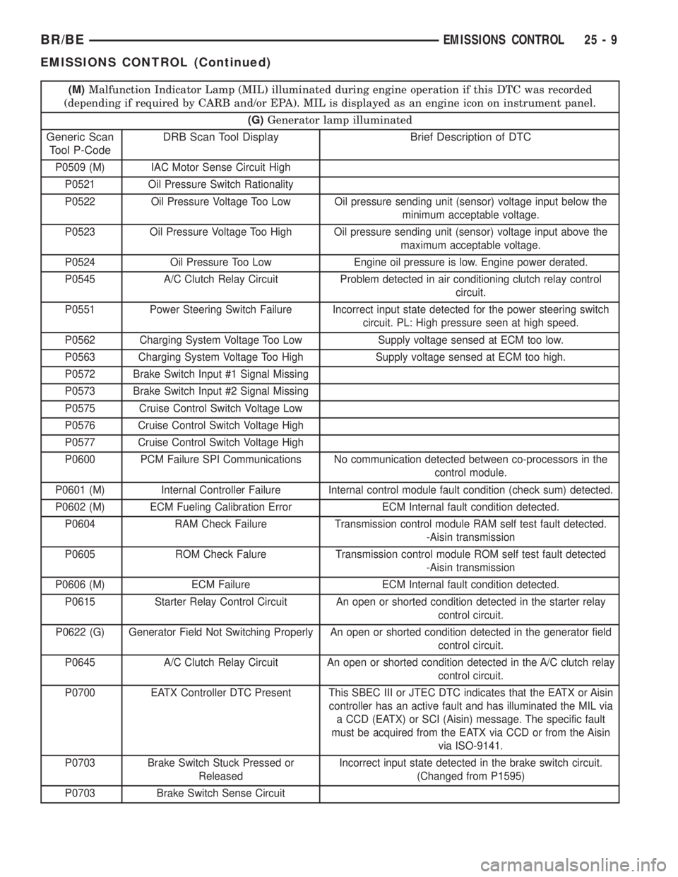
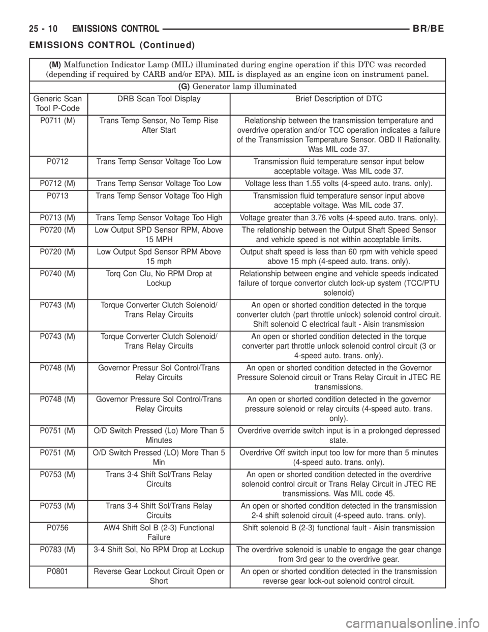
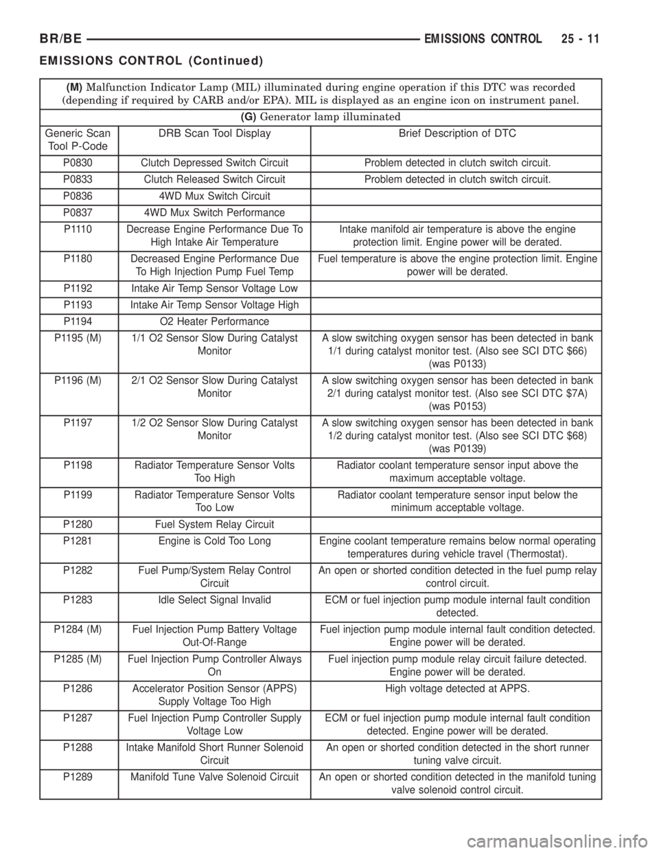
DESCRIPTION - DIAGNOSTIC TROUBLE
CODES..............................2
DESCRIPTION - TASK MANAGER.........17
DESCRIPTION - MONITORED SYSTEMS . . . 17
DESCRIPTION - TRIP DEFINITION........19
DESCRIPTION - COMPONENT MONITORS -
GAS ENGINES.......................19DESCRIPTION - COMPONENT MONITORS -
DIESEL ENGINES.....................20
OPERATION
OPERATION - GAS ENGINES............20
OPERATION - DIESEL..................20
OPERATION - TASK MANAGER..........21
OPERATION - NON-MONITORED
CIRCUITS - GAS ENGINES..............24
OPERATION - NON-MONITORED
CIRCUITS - DIESEL....................24
AIR INJECTION.........................26
EVAPORATIVE EMISSIONS................32
EMISSIONS CONTROL
DESCRIPTION
DESCRIPTION - DIESEL
Two different modules are used for powertrain con-
trol with the diesel engine. The Powertrain Control
Module (PCM) is used primarily for charging system,
transmission, A/C compressor clutch operation and
speed control functions. The Engine Control Module
(ECM) is used to control thefuel and emissions
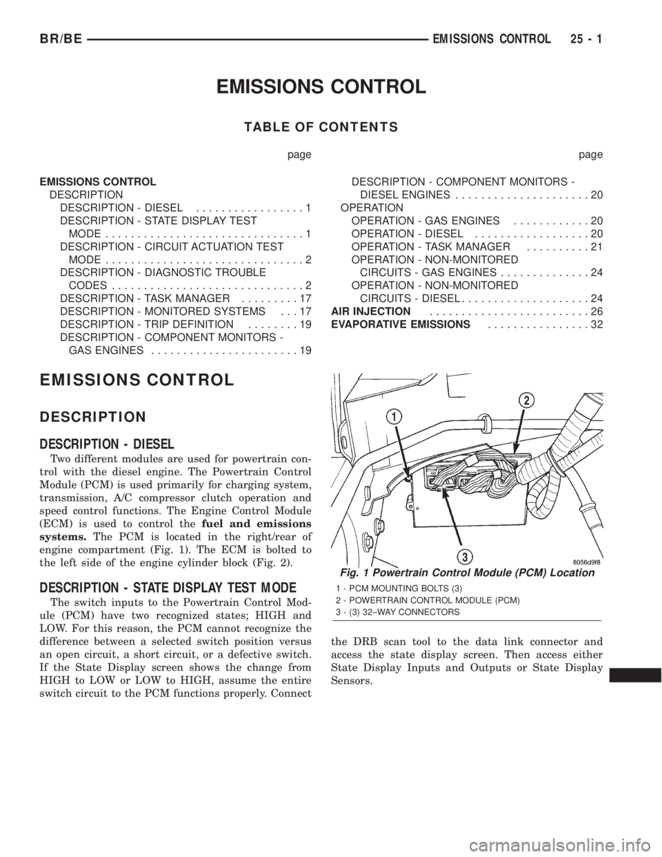
systems.The PCM is located in the right/rear of
engine compartment (Fig. 1). The ECM is bolted to
the left side of the engine cylinder block (Fig. 2).
DESCRIPTION - STATE DISPLAY TEST MODE
The switch inputs to the Powertrain Control Mod-
ule (PCM) have two recognized states; HIGH and
LOW. For this reason, the PCM cannot recognize the
difference between a selected switch position versus
an open circuit, a short circuit, or a defective switch.
If the State Display screen shows the change from
HIGH to LOW or LOW to HIGH, assume the entire
switch circuit to the PCM functions properly. Connectthe DRB scan tool to the data link connector and
access the state display screen. Then access either
State Display Inputs and Outputs or State Display
Sensors.
Fig. 1 Powertrain Control Module (PCM) Location
1 - PCM MOUNTING BOLTS (3)
2 - POWERTRAIN CONTROL MODULE (PCM)
3 - (3) 32±WAY CONNECTORS
BR/BEEMISSIONS CONTROL 25 - 1
Page 2188 of 2255
(M)Malfunction Indicator Lamp (MIL) illuminated during engine operation if this DTC was recorded
(depending if required by CARB and/or EPA). MIL is displayed as an engine icon on instrument panel.
(G)Generator lamp illuminated
Generic Scan
Tool P-CodeDRB Scan Tool Display Brief Description of DTC
P0509 (M) IAC Motor Sense Circuit High
P0521 Oil Pressure Switch Rationality
P0522 Oil Pressure Voltage Too Low Oil pressure sending unit (sensor) voltage input below the
minimum acceptable voltage.
P0523 Oil Pressure Voltage Too High Oil pressure sending unit (sensor) voltage input above the
maximum acceptable voltage.
P0524 Oil Pressure Too Low Engine oil pressure is low. Engine power derated.
P0545 A/C Clutch Relay Circuit Problem detected in air conditioning clutch relay control
circuit.
P0551 Power Steering Switch Failure Incorrect input state detected for the power steering switch
circuit. PL: High pressure seen at high speed.
P0562 Charging System Voltage Too Low Supply voltage sensed at ECM too low.
P0563 Charging System Voltage Too High Supply voltage sensed at ECM too high.
P0572 Brake Switch Input #1 Signal Missing
P0573 Brake Switch Input #2 Signal Missing
P0575 Cruise Control Switch Voltage Low
P0576 Cruise Control Switch Voltage High
P0577 Cruise Control Switch Voltage High
P0600 PCM Failure SPI Communications No communication detected between co-processors in the
control module.
P0601 (M) Internal Controller Failure Internal control module fault condition (check sum) detected.
P0602 (M) ECM Fueling Calibration Error ECM Internal fault condition detected.
P0604 RAM Check Failure Transmission control module RAM self test fault detected.
-Aisin transmission
P0605 ROM Check Falure Transmission control module ROM self test fault detected
-Aisin transmission
P0606 (M) ECM Failure ECM Internal fault condition detected.
P0615 Starter Relay Control Circuit An open or shorted condition detected in the starter relay
control circuit.
P0622 (G) Generator Field Not Switching Properly An open or shorted condition detected in the generator field
control circuit.
P0645 A/C Clutch Relay Circuit An open or shorted condition detected in the A/C clutch relay
control circuit.
P0700 EATX Controller DTC Present This SBEC III or JTEC DTC indicates that the EATX or Aisin
controller has an active fault and has illuminated the MIL via
a CCD (EATX) or SCI (Aisin) message. The specific fault
must be acquired from the EATX via CCD or from the Aisin
via ISO-9141.
P0703 Brake Switch Stuck Pressed or
ReleasedIncorrect input state detected in the brake switch circuit.
(Changed from P1595)
P0703 Brake Switch Sense Circuit
BR/BEEMISSIONS CONTROL 25 - 9
EMISSIONS CONTROL (Continued)
Page 2189 of 2255
(M)Malfunction Indicator Lamp (MIL) illuminated during engine operation if this DTC was recorded
(depending if required by CARB and/or EPA). MIL is displayed as an engine icon on instrument panel.
(G)Generator lamp illuminated
Generic Scan
Tool P-CodeDRB Scan Tool Display Brief Description of DTC
P0711 (M) Trans Temp Sensor, No Temp Rise
After StartRelationship between the transmission temperature and
overdrive operation and/or TCC operation indicates a failure
of the Transmission Temperature Sensor. OBD II Rationality.
Was MIL code 37.
P0712 Trans Temp Sensor Voltage Too Low Transmission fluid temperature sensor input below
acceptable voltage. Was MIL code 37.
P0712 (M) Trans Temp Sensor Voltage Too Low Voltage less than 1.55 volts (4-speed auto. trans. only).
P0713 Trans Temp Sensor Voltage Too High Transmission fluid temperature sensor input above
acceptable voltage. Was MIL code 37.
P0713 (M) Trans Temp Sensor Voltage Too High Voltage greater than 3.76 volts (4-speed auto. trans. only).
P0720 (M) Low Output SPD Sensor RPM, Above
15 MPHThe relationship between the Output Shaft Speed Sensor
and vehicle speed is not within acceptable limits.
P0720 (M) Low Output Spd Sensor RPM Above
15 mphOutput shaft speed is less than 60 rpm with vehicle speed
above 15 mph (4-speed auto. trans. only).
P0740 (M) Torq Con Clu, No RPM Drop at
LockupRelationship between engine and vehicle speeds indicated
failure of torque convertor clutch lock-up system (TCC/PTU
solenoid)
P0743 (M) Torque Converter Clutch Solenoid/
Trans Relay CircuitsAn open or shorted condition detected in the torque
converter clutch (part throttle unlock) solenoid control circuit.
Shift solenoid C electrical fault - Aisin transmission
P0743 (M) Torque Converter Clutch Solenoid/
Trans Relay CircuitsAn open or shorted condition detected in the torque
converter part throttle unlock solenoid control circuit (3 or
4-speed auto. trans. only).
P0748 (M) Governor Pressur Sol Control/Trans
Relay CircuitsAn open or shorted condition detected in the Governor
Pressure Solenoid circuit or Trans Relay Circuit in JTEC RE
transmissions.
P0748 (M) Governor Pressure Sol Control/Trans
Relay CircuitsAn open or shorted condition detected in the governor
pressure solenoid or relay circuits (4-speed auto. trans.
only).
P0751 (M) O/D Switch Pressed (Lo) More Than 5
MinutesOverdrive override switch input is in a prolonged depressed
state.
P0751 (M) O/D Switch Pressed (LO) More Than 5
MinOverdrive Off switch input too low for more than 5 minutes
(4-speed auto. trans. only).
P0753 (M) Trans 3-4 Shift Sol/Trans Relay
CircuitsAn open or shorted condition detected in the overdrive
solenoid control circuit or Trans Relay Circuit in JTEC RE
transmissions. Was MIL code 45.
P0753 (M) Trans 3-4 Shift Sol/Trans Relay
CircuitsAn open or shorted condition detected in the transmission
2-4 shift solenoid circuit (4-speed auto. trans. only).
P0756 AW4 Shift Sol B (2-3) Functional
FailureShift solenoid B (2-3) functional fault - Aisin transmission
P0783 (M) 3-4 Shift Sol, No RPM Drop at Lockup The overdrive solenoid is unable to engage the gear change
from 3rd gear to the overdrive gear.
P0801 Reverse Gear Lockout Circuit Open or
ShortAn open or shorted condition detected in the transmission
reverse gear lock-out solenoid control circuit.
25 - 10 EMISSIONS CONTROLBR/BE
EMISSIONS CONTROL (Continued)
Page 2190 of 2255
(M)Malfunction Indicator Lamp (MIL) illuminated during engine operation if this DTC was recorded
(depending if required by CARB and/or EPA). MIL is displayed as an engine icon on instrument panel.
(G)Generator lamp illuminated
Generic Scan
Tool P-CodeDRB Scan Tool Display Brief Description of DTC
P0830 Clutch Depressed Switch Circuit Problem detected in clutch switch circuit.
P0833 Clutch Released Switch Circuit Problem detected in clutch switch circuit.
P0836 4WD Mux Switch Circuit
P0837 4WD Mux Switch Performance
P1110 Decrease Engine Performance Due To
High Intake Air TemperatureIntake manifold air temperature is above the engine
protection limit. Engine power will be derated.
P1180 Decreased Engine Performance Due
To High Injection Pump Fuel TempFuel temperature is above the engine protection limit. Engine
power will be derated.
P1192 Intake Air Temp Sensor Voltage Low
P1193 Intake Air Temp Sensor Voltage High
P1194 O2 Heater Performance
P1195 (M) 1/1 O2 Sensor Slow During Catalyst
MonitorA slow switching oxygen sensor has been detected in bank
1/1 during catalyst monitor test. (Also see SCI DTC $66)
(was P0133)
P1196 (M) 2/1 O2 Sensor Slow During Catalyst
MonitorA slow switching oxygen sensor has been detected in bank
2/1 during catalyst monitor test. (Also see SCI DTC $7A)
(was P0153)
P1197 1/2 O2 Sensor Slow During Catalyst
MonitorA slow switching oxygen sensor has been detected in bank
1/2 during catalyst monitor test. (Also see SCI DTC $68)
(was P0139)
P1198 Radiator Temperature Sensor Volts
Too HighRadiator coolant temperature sensor input above the
maximum acceptable voltage.
P1199 Radiator Temperature Sensor Volts
Too LowRadiator coolant temperature sensor input below the
minimum acceptable voltage.
P1280 Fuel System Relay Circuit
P1281 Engine is Cold Too Long Engine coolant temperature remains below normal operating
temperatures during vehicle travel (Thermostat).
P1282 Fuel Pump/System Relay Control
CircuitAn open or shorted condition detected in the fuel pump relay
control circuit.
P1283 Idle Select Signal Invalid ECM or fuel injection pump module internal fault condition
detected.
P1284 (M) Fuel Injection Pump Battery Voltage
Out-Of-RangeFuel injection pump module internal fault condition detected.
Engine power will be derated.
P1285 (M) Fuel Injection Pump Controller Always
OnFuel injection pump module relay circuit failure detected.
Engine power will be derated.
P1286 Accelerator Position Sensor (APPS)
Supply Voltage Too HighHigh voltage detected at APPS.
P1287 Fuel Injection Pump Controller Supply
Voltage LowECM or fuel injection pump module internal fault condition
detected. Engine power will be derated.
P1288 Intake Manifold Short Runner Solenoid
CircuitAn open or shorted condition detected in the short runner
tuning valve circuit.
P1289 Manifold Tune Valve Solenoid Circuit An open or shorted condition detected in the manifold tuning
valve solenoid control circuit.
BR/BEEMISSIONS CONTROL 25 - 11
EMISSIONS CONTROL (Continued)
Page 2193 of 2255
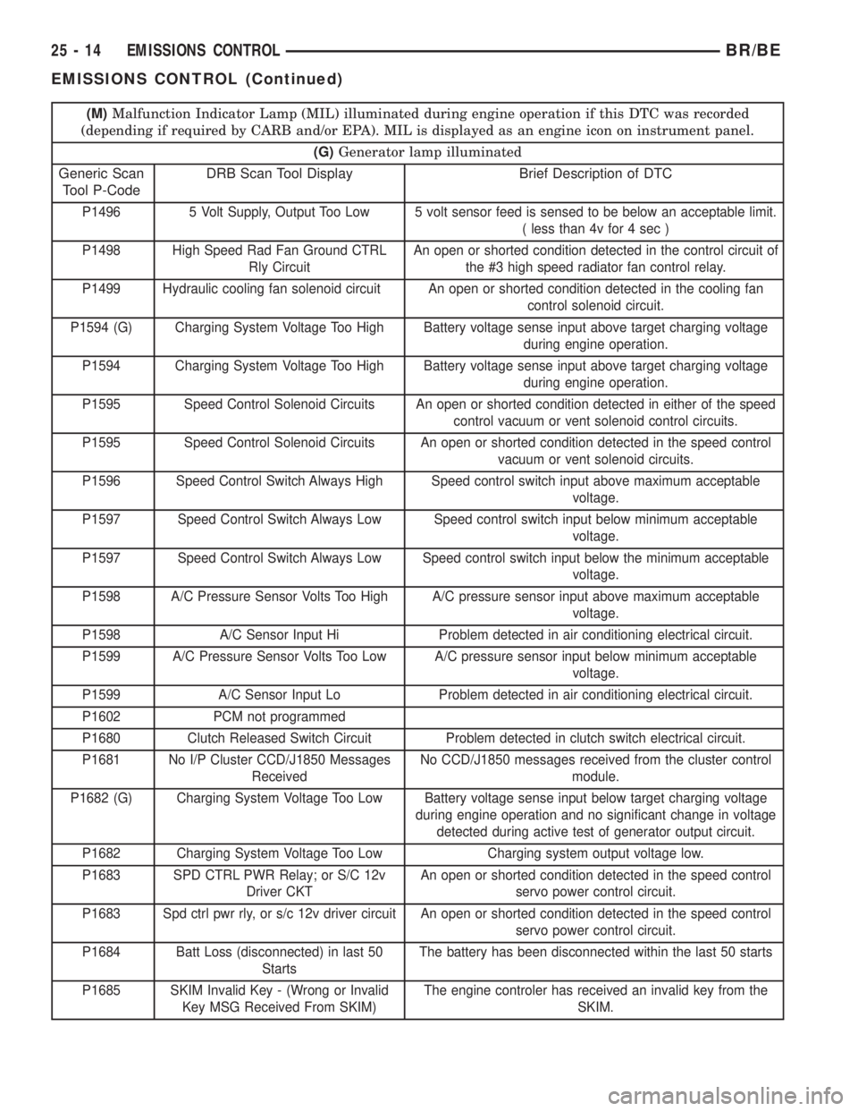
(M)Malfunction Indicator Lamp (MIL) illuminated during engine operation if this DTC was recorded
(depending if required by CARB and/or EPA). MIL is displayed as an engine icon on instrument panel.
(G)Generator lamp illuminated
Generic Scan
Tool P-CodeDRB Scan Tool Display Brief Description of DTC
P1496 5 Volt Supply, Output Too Low 5 volt sensor feed is sensed to be below an acceptable limit.
( less than 4v for 4 sec )
P1498 High Speed Rad Fan Ground CTRL
Rly CircuitAn open or shorted condition detected in the control circuit of
the #3 high speed radiator fan control relay.
P1499 Hydraulic cooling fan solenoid circuit An open or shorted condition detected in the cooling fan
control solenoid circuit.
P1594 (G) Charging System Voltage Too High Battery voltage sense input above target charging voltage
during engine operation.
P1594 Charging System Voltage Too High Battery voltage sense input above target charging voltage
during engine operation.
P1595 Speed Control Solenoid Circuits An open or shorted condition detected in either of the speed
control vacuum or vent solenoid control circuits.
P1595 Speed Control Solenoid Circuits An open or shorted condition detected in the speed control
vacuum or vent solenoid circuits.
P1596 Speed Control Switch Always High Speed control switch input above maximum acceptable
voltage.
P1597 Speed Control Switch Always Low Speed control switch input below minimum acceptable
voltage.
P1597 Speed Control Switch Always Low Speed control switch input below the minimum acceptable
voltage.
P1598 A/C Pressure Sensor Volts Too High A/C pressure sensor input above maximum acceptable
voltage.
P1598 A/C Sensor Input Hi Problem detected in air conditioning electrical circuit.
P1599 A/C Pressure Sensor Volts Too Low A/C pressure sensor input below minimum acceptable
voltage.
P1599 A/C Sensor Input Lo Problem detected in air conditioning electrical circuit.
P1602 PCM not programmed
P1680 Clutch Released Switch Circuit Problem detected in clutch switch electrical circuit.
P1681 No I/P Cluster CCD/J1850 Messages
ReceivedNo CCD/J1850 messages received from the cluster control
module.
P1682 (G) Charging System Voltage Too Low Battery voltage sense input below target charging voltage
during engine operation and no significant change in voltage
detected during active test of generator output circuit.
P1682 Charging System Voltage Too Low Charging system output voltage low.
P1683 SPD CTRL PWR Relay; or S/C 12v
Driver CKTAn open or shorted condition detected in the speed control
servo power control circuit.
P1683 Spd ctrl pwr rly, or s/c 12v driver circuit An open or shorted condition detected in the speed control
servo power control circuit.
P1684 Batt Loss (disconnected) in last 50
StartsThe battery has been disconnected within the last 50 starts
P1685 SKIM Invalid Key - (Wrong or Invalid
Key MSG Received From SKIM)The engine controler has received an invalid key from the
SKIM.
25 - 14 EMISSIONS CONTROLBR/BE
EMISSIONS CONTROL (Continued)
Page 2194 of 2255
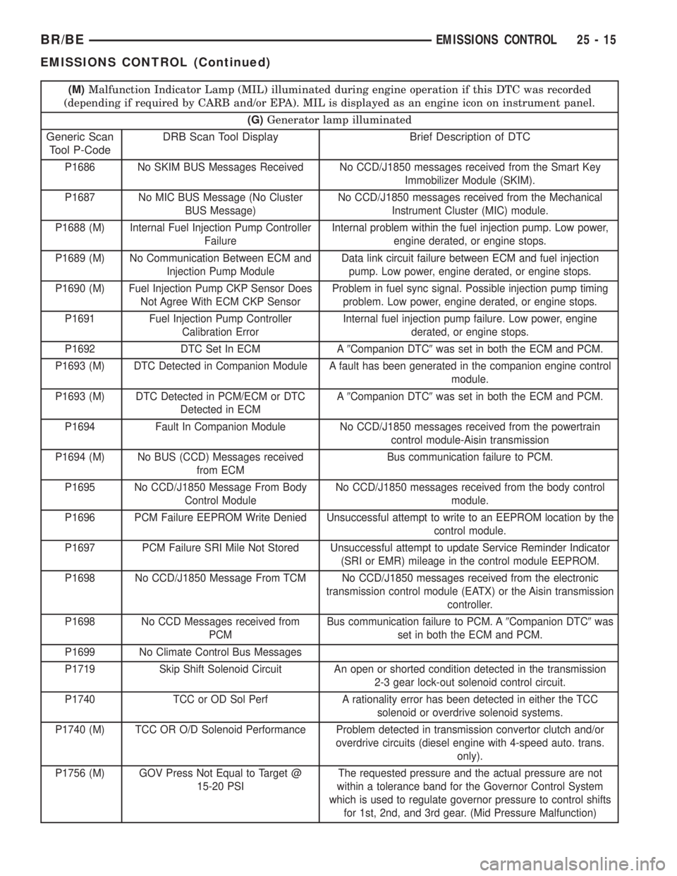
(M)Malfunction Indicator Lamp (MIL) illuminated during engine operation if this DTC was recorded
(depending if required by CARB and/or EPA). MIL is displayed as an engine icon on instrument panel.
(G)Generator lamp illuminated
Generic Scan
Tool P-CodeDRB Scan Tool Display Brief Description of DTC
P1686 No SKIM BUS Messages Received No CCD/J1850 messages received from the Smart Key
Immobilizer Module (SKIM).
P1687 No MIC BUS Message (No Cluster
BUS Message)No CCD/J1850 messages received from the Mechanical
Instrument Cluster (MIC) module.
P1688 (M) Internal Fuel Injection Pump Controller
FailureInternal problem within the fuel injection pump. Low power,
engine derated, or engine stops.
P1689 (M) No Communication Between ECM and
Injection Pump ModuleData link circuit failure between ECM and fuel injection
pump. Low power, engine derated, or engine stops.
P1690 (M) Fuel Injection Pump CKP Sensor Does
Not Agree With ECM CKP SensorProblem in fuel sync signal. Possible injection pump timing
problem. Low power, engine derated, or engine stops.
P1691 Fuel Injection Pump Controller
Calibration ErrorInternal fuel injection pump failure. Low power, engine
derated, or engine stops.
P1692 DTC Set In ECM A9Companion DTC9was set in both the ECM and PCM.
P1693 (M) DTC Detected in Companion Module A fault has been generated in the companion engine control
module.
P1693 (M) DTC Detected in PCM/ECM or DTC
Detected in ECMA9Companion DTC9was set in both the ECM and PCM.
P1694 Fault In Companion Module No CCD/J1850 messages received from the powertrain
control module-Aisin transmission
P1694 (M) No BUS (CCD) Messages received
from ECMBus communication failure to PCM.
P1695 No CCD/J1850 Message From Body
Control ModuleNo CCD/J1850 messages received from the body control
module.
P1696 PCM Failure EEPROM Write Denied Unsuccessful attempt to write to an EEPROM location by the
control module.
P1697 PCM Failure SRI Mile Not Stored Unsuccessful attempt to update Service Reminder Indicator
(SRI or EMR) mileage in the control module EEPROM.
P1698 No CCD/J1850 Message From TCM No CCD/J1850 messages received from the electronic
transmission control module (EATX) or the Aisin transmission
controller.
P1698 No CCD Messages received from
PCMBus communication failure to PCM. A9Companion DTC9was
set in both the ECM and PCM.
P1699 No Climate Control Bus Messages
P1719 Skip Shift Solenoid Circuit An open or shorted condition detected in the transmission
2-3 gear lock-out solenoid control circuit.
P1740 TCC or OD Sol Perf A rationality error has been detected in either the TCC
solenoid or overdrive solenoid systems.
P1740 (M) TCC OR O/D Solenoid Performance Problem detected in transmission convertor clutch and/or
overdrive circuits (diesel engine with 4-speed auto. trans.
only).
P1756 (M) GOV Press Not Equal to Target @
15-20 PSIThe requested pressure and the actual pressure are not
within a tolerance band for the Governor Control System
which is used to regulate governor pressure to control shifts
for 1st, 2nd, and 3rd gear. (Mid Pressure Malfunction)
BR/BEEMISSIONS CONTROL 25 - 15
EMISSIONS CONTROL (Continued)
Page 2195 of 2255
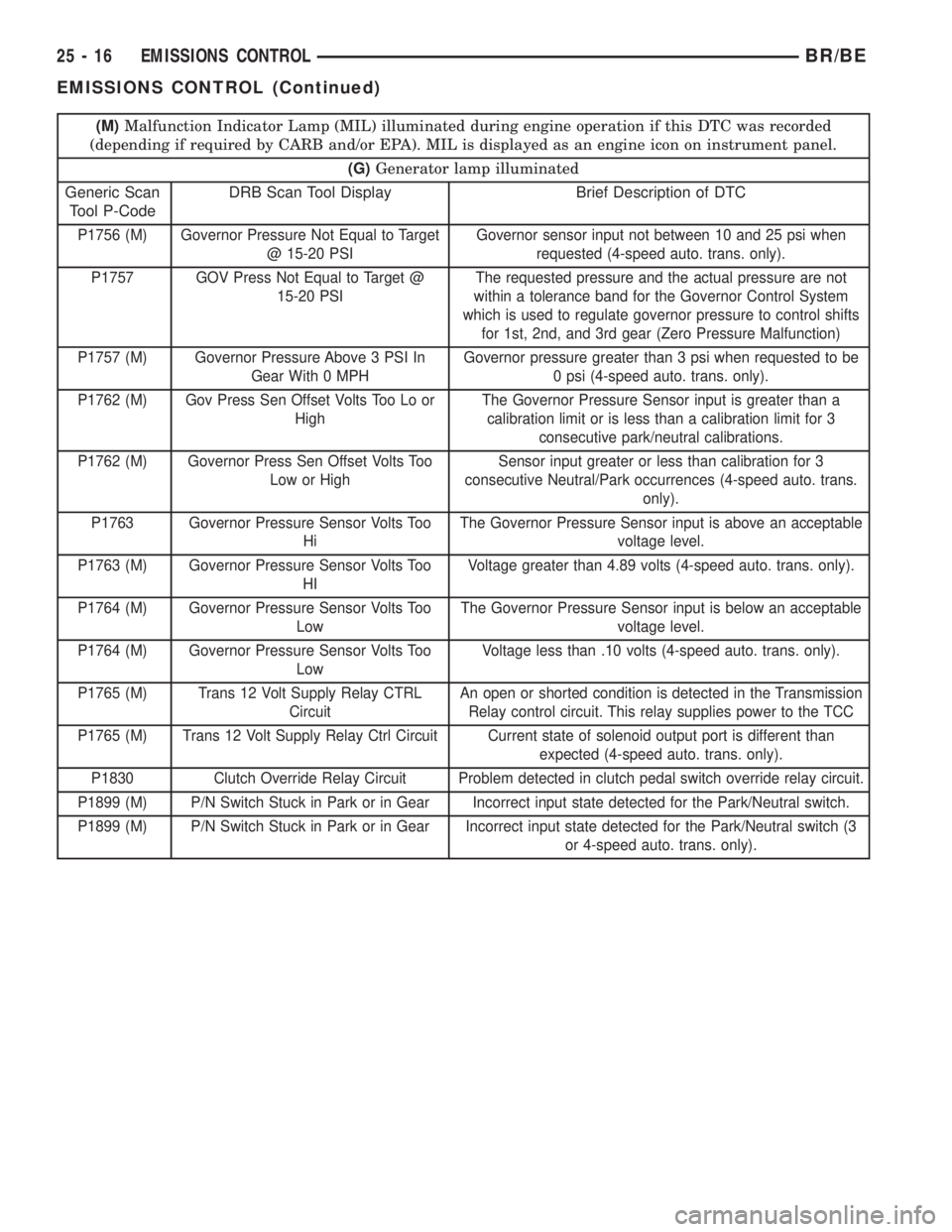
(M)Malfunction Indicator Lamp (MIL) illuminated during engine operation if this DTC was recorded
(depending if required by CARB and/or EPA). MIL is displayed as an engine icon on instrument panel.
(G)Generator lamp illuminated
Generic Scan
Tool P-CodeDRB Scan Tool Display Brief Description of DTC
P1756 (M) Governor Pressure Not Equal to Target
@ 15-20 PSIGovernor sensor input not between 10 and 25 psi when
requested (4-speed auto. trans. only).
P1757 GOV Press Not Equal to Target @
15-20 PSIThe requested pressure and the actual pressure are not
within a tolerance band for the Governor Control System
which is used to regulate governor pressure to control shifts
for 1st, 2nd, and 3rd gear (Zero Pressure Malfunction)
P1757 (M) Governor Pressure Above 3 PSI In
Gear With 0 MPHGovernor pressure greater than 3 psi when requested to be
0 psi (4-speed auto. trans. only).
P1762 (M) Gov Press Sen Offset Volts Too Lo or
HighThe Governor Pressure Sensor input is greater than a
calibration limit or is less than a calibration limit for 3
consecutive park/neutral calibrations.
P1762 (M) Governor Press Sen Offset Volts Too
Low or HighSensor input greater or less than calibration for 3
consecutive Neutral/Park occurrences (4-speed auto. trans.
only).
P1763 Governor Pressure Sensor Volts Too
HiThe Governor Pressure Sensor input is above an acceptable
voltage level.
P1763 (M) Governor Pressure Sensor Volts Too
HIVoltage greater than 4.89 volts (4-speed auto. trans. only).
P1764 (M) Governor Pressure Sensor Volts Too
LowThe Governor Pressure Sensor input is below an acceptable
voltage level.
P1764 (M) Governor Pressure Sensor Volts Too
LowVoltage less than .10 volts (4-speed auto. trans. only).
P1765 (M) Trans 12 Volt Supply Relay CTRL
CircuitAn open or shorted condition is detected in the Transmission
Relay control circuit. This relay supplies power to the TCC
P1765 (M) Trans 12 Volt Supply Relay Ctrl Circuit Current state of solenoid output port is different than
expected (4-speed auto. trans. only).
P1830 Clutch Override Relay Circuit Problem detected in clutch pedal switch override relay circuit.
P1899 (M) P/N Switch Stuck in Park or in Gear Incorrect input state detected for the Park/Neutral switch.
P1899 (M) P/N Switch Stuck in Park or in Gear Incorrect input state detected for the Park/Neutral switch (3
or 4-speed auto. trans. only).
25 - 16 EMISSIONS CONTROLBR/BE
EMISSIONS CONTROL (Continued)
Page 2218 of 2255
ABS - DESCRIPTION, BRAKES...........5-35
ABS - OPERATION, BRAKES.............5-36
ABS BRAKE SYSTEM - STANDARD
PROCEDURE, BLEEDING................5-36
ABS INDICATOR - DESCRIPTION.........8J-14
ABS INDICATOR - OPERATION..........8J-14
A/C APPLICATION TABLE,
SPECIFICATIONS......................24-7
A/C COMPRESSOR - DESCRIPTION......24-46
A/C COMPRESSOR - DIAGNOSIS AND
TESTING...........................24-47
A/C COMPRESSOR - INSTALLATION......24-48
A/C COMPRESSOR - OPERATION........24-46
A/C COMPRESSOR - REMOVAL.........24-47
A/C COMPRESSOR CLUTCH -
DESCRIPTION.......................24-11
A/C COMPRESSOR CLUTCH -
INSPECTION........................24-15
A/C COMPRESSOR CLUTCH -
INSTALLATION.......................24-15
A/C COMPRESSOR CLUTCH -
OPERATION.........................24-13
A/C COMPRESSOR CLUTCH - REMOVAL . . 24-13
A/C COMPRESSOR CLUTCH BREAK-IN -
STANDARD PROCEDURE...............24-13
A/C COMPRESSOR CLUTCH COIL -
DIAGNOSIS AND TESTING.............24-13
A/C COMPRESSOR CLUTCH RELAY -
DESCRIPTION.......................24-17
A/C COMPRESSOR CLUTCH RELAY -
DIAGNOSIS AND TESTING...............24-17
A/C COMPRESSOR CLUTCH RELAY -
INSTALLATION.......................24-18
A/C COMPRESSOR CLUTCH RELAY -
OPERATION.........................24-17
A/C COMPRESSOR CLUTCH RELAY -
REMOVAL..........................24-18
A/C CONDENSER - DESCRIPTION........24-49
A/C CONDENSER - INSTALLATION.......24-50
A/C CONDENSER - OPERATION..........24-49
A/C CONDENSER - REMOVAL...........24-49
A/C EVAPORATOR - DESCRIPTION.......24-53
A/C EVAPORATOR - INSTALLATION......24-53
A/C EVAPORATOR - OPERATION.........24-53
A/C EVAPORATOR - REMOVAL..........24-53
A/C HEATER CONTROL - DIAGNOSIS
AND TESTING.......................24-18
A/C HIGH PRESSURE SWITCH -
DESCRIPTION.......................24-20
A/C HIGH PRESSURE SWITCH -
DIAGNOSIS AND TESTING.............24-20
A/C HIGH PRESSURE SWITCH -
INSTALLATION.......................24-20
A/C HIGH PRESSURE SWITCH -
OPERATION.........................24-20
A/C HIGH PRESSURE SWITCH -
REMOVAL..........................24-20
A/C LINE COUPLERS - DESCRIPTION.....24-40
A/C LINE COUPLERS - OPERATION......24-41
A/C LINE COUPLERS - STANDARD
PROCEDURE........................24-44
A/C LOW PRESSURE SWITCH -
DESCRIPTION.......................24-21
A/C LOW PRESSURE SWITCH -
DIAGNOSIS AND TESTING.............24-21
A/C LOW PRESSURE SWITCH -
INSTALLATION.......................24-21
A/C LOW PRESSURE SWITCH -
OPERATION
.........................24-21
A/C LOW PRESSURE SWITCH -
REMOVAL
..........................24-21
A/C ORIFICE TUBE - DESCRIPTION
.......24-54
A/C ORIFICE TUBE - INSTALLATION
......24-54
A/C ORIFICE TUBE - OPERATION
........24-54
A/C ORIFICE TUBE - REMOVAL
..........24-54
A/C PERFORMANCE - DIAGNOSIS AND
TESTING
............................24-2
ACCELERATOR PEDAL - INSTALLATION
. . . 14-37
ACCELERATOR PEDAL - REMOVAL
.......14-36
ACCELERATOR PEDAL POSITION
SENSOR - DESCRIPTION
...............14-95
ACCELERATOR PEDAL POSITION
SENSOR - INSTALLATION
..............14-97
ACCELERATOR PEDAL POSITION
SENSOR - OPERATION
................14-95
ACCELERATOR PEDAL POSITION
SENSOR - REMOVAL
..................14-95ACCESSORY DRIVE BELT - DIAGNOSIS
AND TESTING................7-24,7-27,7-30
ACCUMULATOR - DESCRIPTION.........24-55
ACCUMULATOR - DESCRIPTION . . 21-149,21-319
ACCUMULATOR - INSPECTION . . . 21-150,21-320
ACCUMULATOR - INSTALLATION........24-55
ACCUMULATOR - OPERATION..........24-55
ACCUMULATOR - OPERATION....21-150,21-320
ACCUMULATOR - REMOVAL............24-55
A/C-HEATER CONTROL - DESCRIPTION . . . 24-18
A/C-HEATER CONTROL - INSTALLATION . . . 24-19
A/C-HEATER CONTROL - OPERATION.....24-18
A/C-HEATER CONTROL - REMOVAL......24-19
ACTUATION TEST MODE - DESCRIPTION,
CIRCUIT.............................25-2
ACTUATOR - INSTALLATION, BLEND
DOOR.............................24-25
ACTUATOR - INSTALLATION, HEAT/
DEFROST DOOR.....................24-27
ACTUATOR - INSTALLATION, INSIDE
HANDLE.......................23-72,23-80
ACTUATOR - INSTALLATION, PANEL/
DEFROST DOOR.....................24-27
ACTUATOR - INSTALLATION,
RECIRCULATION DOOR................24-28
ACTUATOR - REMOVAL, BLEND DOOR....24-25
ACTUATOR - REMOVAL, HEAT/DEFROST
DOOR.............................24-26
ACTUATOR - REMOVAL, INSIDE HANDLE . 23-72,
23-80
ACTUATOR - REMOVAL, PANEL/DEFROST
DOOR.............................24-26
ACTUATOR - REMOVAL, RECIRCULATION
DOOR.............................24-27
ADAPTER - INSTALLATION, DEFROSTER
AND DEMISTER DUCT.................24-33
ADAPTER - REMOVAL, DEFROSTER AND
DEMISTER DUCT.....................24-33
ADAPTER BRACKET - INSTALLATION,
CAB CHASSIS.......................13-10
ADAPTER BRACKET - REMOVAL, CAB
CHASSIS...........................13-10
ADAPTER HOUSING SEAL - NV4500 -
INSTALLATION.......................21-42
ADAPTER HOUSING SEAL - NV4500 -
REMOVAL..........................21-42
ADAPTER HOUSING SEAL - NV5600 -
INSTALLATION.......................21-85
ADAPTER HOUSING SEAL - NV5600 -
REMOVAL..........................21-85
ADDING ADDITIONAL COOLANT -
STANDARD PROCEDURE................7-16
ADDITIONAL COOLANT - STANDARD
PROCEDURE, ADDING..................7-16
ADDITIVES - STANDARD PROCEDURE,
COOLANT SELECTION..................7-17
ADHESIVE LOCATIONS, SPECIFICATIONS
- STRUCTURAL......................23-44
ADJUSTER - INSTALLATION, SEAT BELT
TURNING LOOP.....................8O-29
ADJUSTER - INSTALLATION, SEAT
TRACK............................23-143
ADJUSTER - REMOVAL, SEAT BELT
TURNING LOOP.....................8O-29
ADJUSTER - REMOVAL, SEAT TRACK....23-143
ADJUSTER ASSEMBLY - INSTALLATION,
ROCKER ARM........................9-26
ADJUSTER ASSEMBLY - REMOVAL,
ROCKER ARM........................9-26
ADJUSTER ASSY - CLEANING, ROCKER
ARM ..............................9-146
ADJUSTER ASSY - DESCRIPTION,
ROCKER ARM.......................9-145
ADJUSTER ASSY - INSPECTION,
ROCKER ARM.......................9-146
ADJUSTER ASSY - INSTALLATION,
ROCKER ARM...................9-148,9-84
ADJUSTER ASSY - REMOVAL, ROCKER
ARM ..........................9-145,9-84
ADJUSTER KNOB - INSTALLATION,
TURNING LOOP HGT
.................8O-30
ADJUSTER KNOB - REMOVAL, TURNING
LOOP HGT
..........................8O-30
ADJUSTMENT - STANDARD
PROCEDURE, COMPASS VARIATION
......8M-4
ADJUSTMENT, ADJUSTMENTS
. . . 23-101,23-102,
23-103
ADJUSTMENT, ADJUSTMENTS
...........5-30ADJUSTMENT, ADJUSTMENTS...........13-2
ADJUSTMENT, ADJUSTMENTS . . . 21-208,21-380
ADJUSTMENT AND VERIFICATION -
STANDARD PROCEDURE, VALVE LASH....9-141
ADJUSTMENT, BANDS..........21-151,21-321
ADJUSTMENT, CARGO DOOR...........23-78
ADJUSTMENT, CENTER BEARING..........3-8
ADJUSTMENT, FRONT DOOR FORE/AFT . . . 23-69
ADJUSTMENT, FRONT DOOR IN/OUT.....23-70
ADJUSTMENT, FRONT DOOR LATCH......23-73
ADJUSTMENT, FRONT DOOR UP/DOWN . . . 23-70
ADJUSTMENT, PARKING BRAKE SHOES....5-33
ADJUSTMENT, SHIFT LEVER.....21-463,21-500
ADJUSTMENTS - ADJUSTMENT . . 23-101,23-102,
23-103
ADJUSTMENTS - ADJUSTMENT..........5-30
ADJUSTMENTS - ADJUSTMENT..........13-2
ADJUSTMENTS - ADJUSTMENT . . 21-208,21-380
ADJUSTMENTS, FOG LAMP UNIT........8L-13
ADJUSTMENTS, FRONT AXLE - 248FBI....3-19
ADJUSTMENTS, GEAR.................19-18
ADJUSTMENTS, HEADLAMP UNIT.......8L-21
ADJUSTMENTS, REAR AXLE - 248RBI.....3-51
ADJUSTMENTS, REAR AXLE - 267RBI.....3-83
ADJUSTMENTS, REAR AXLE - 286RBI....3-112
ADJUSTMENTS, TRANSMISSION
THROTTLE VALVE CABLE.........21-210,21-382
ADJUSTMENTS, VALVE BODY....21-257,21-428
AIR BLEED - STANDARD PROCEDURE....14-61
AIR CLEANER ELEMENT - INSTALLATION . . 9-130
AIR CLEANER ELEMENT - REMOVAL.....9-129
AIR CONDITIONER - DESCRIPTION,
HEATER .............................24-1
AIR CONDITIONER - OPERATION,
HEATER .............................24-1
AIR CONDITIONING - INSTALLATION,
WATER PUMP BYPASS HOSE WITH.......7-76
AIR CONDITIONING - INSTALLATION,
WATER PUMP BYPASS HOSE
WITHOUT............................7-77
AIR CONDITIONING - REMOVAL, WATER
PUMP BYPASS HOSE WITH.............7-73
AIR CONDITIONING - REMOVAL, WATER
PUMP BYPASS HOSE WITHOUT..........7-76
AIR CONTROL MOTOR - DESCRIPTION,
IDLE...............................14-40
AIR CONTROL MOTOR - OPERATION,
IDLE...............................14-40
AIR COOLER AND PLUMBING -
CLEANING, CHARGE..................11-19
AIR COOLER AND PLUMBING -
DESCRIPTION, CHARGE...............11-18
AIR COOLER AND PLUMBING -
INSPECTION, CHARGE.................11-19
AIR COOLER AND PLUMBING -
INSTALLATION, CHARGE...............11-20
AIR COOLER AND PLUMBING -
OPERATION, CHARGE.................11-18
AIR COOLER AND PLUMBING -
REMOVAL, CHARGE..................11-18
AIR COOLER SYSTEM - LEAKS -
DIAGNOSIS AND TESTING, CHARGE......11-18
AIR DAM - INSTALLATION, FRONT........13-2
AIR DAM - REMOVAL, FRONT...........13-2
AIR EXHAUSTER - INSTALLATION.......23-77
AIR EXHAUSTER - REMOVAL...........23-77
AIR HEATER - DESCRIPTION, INTAKE....14-104
AIR HEATER - INSTALLATION, INTAKE . . . 14-105
AIR HEATER - OPERATION, INTAKE.....14-104
AIR HEATER - REMOVAL, INTAKE.......14-104
AIR HEATER RELAY - DESCRIPTION,
INTAKE............................14-105
AIR HEATER RELAY - INSTALLATION,
INTAKE............................14-106
AIR HEATER RELAY - OPERATION,
INTAKE............................14-105
AIR HEATER RELAY - REMOVAL, INTAKE . 14-106
AIR IN FUEL SYSTEM - DIAGNOSIS AND
TESTING...........................14-60
AIR INJECTION PUMP - DESCRIPTION....25-29
AIR INJECTION PUMP - DIAGNOSIS AND
TESTING...........................25-29
AIR INJECTION PUMP - INSTALLATION . . . 25-30
AIR INJECTION PUMP - OPERATION
.....25-29
AIR INJECTION PUMP - REMOVAL
.......25-30
AIR INJECTION SYSTEM - DESCRIPTION
. . 25-26
AIR INJECTION SYSTEM - OPERATION
....25-28
AIR INJECTION SYSTEM - TORQUE
......25-29
BR/BEINDEX 1
Description Group-Page Description Group-Page Description Group-Page