2002 DODGE RAM oil
[x] Cancel search: oilPage 1344 of 2255
(2) Clean the area around the sensor before
removal.
(3) Remove the two sensor mounting bolts.
(4) Remove the sensor from the intake manifold.
INSTALLATION
INSTALLATION - 5.9L
The MAP sensor is located on the front of the
throttle body (Fig. 35). An L-shaped rubber fitting is
used to connect the MAP sensor to throttle body (Fig.
36).
(1) Install rubber L-shaped fitting to MAP sensor.
(2) Position sensor to throttle body while guiding
rubber fitting over throttle body vacuum nipple.
(3) Install MAP sensor mounting bolts (screws).
Tighten screws to 3 N´m (25 in. lbs.) torque.
(4) Install air cleaner.
INSTALLATION - 8.0L
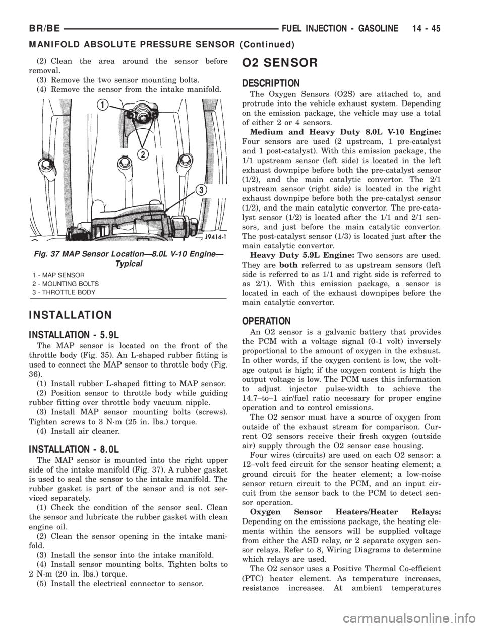
The MAP sensor is mounted into the right upper
side of the intake manifold (Fig. 37). A rubber gasket
is used to seal the sensor to the intake manifold. The
rubber gasket is part of the sensor and is not ser-
viced separately.
(1) Check the condition of the sensor seal. Clean
the sensor and lubricate the rubber gasket with clean
engine oil.
(2) Clean the sensor opening in the intake mani-
fold.
(3) Install the sensor into the intake manifold.
(4) Install sensor mounting bolts. Tighten bolts to
2 N´m (20 in. lbs.) torque.
(5) Install the electrical connector to sensor.
O2 SENSOR
DESCRIPTION
The Oxygen Sensors (O2S) are attached to, and
protrude into the vehicle exhaust system. Depending
on the emission package, the vehicle may use a total
of either 2 or 4 sensors.
Medium and Heavy Duty 8.0L V-10 Engine:
Four sensors are used (2 upstream, 1 pre-catalyst
and 1 post-catalyst). With this emission package, the
1/1 upstream sensor (left side) is located in the left
exhaust downpipe before both the pre-catalyst sensor
(1/2), and the main catalytic convertor. The 2/1
upstream sensor (right side) is located in the right
exhaust downpipe before both the pre-catalyst sensor
(1/2), and the main catalytic convertor. The pre-cata-
lyst sensor (1/2) is located after the 1/1 and 2/1 sen-
sors, and just before the main catalytic convertor.
The post-catalyst sensor (1/3) is located just after the
main catalytic convertor.
Heavy Duty 5.9L Engine:Two sensors are used.
They arebothreferred to as upstream sensors (left
side is referred to as 1/1 and right side is referred to
as 2/1). With this emission package, a sensor is
located in each of the exhaust downpipes before the
main catalytic convertor.
OPERATION
An O2 sensor is a galvanic battery that provides
the PCM with a voltage signal (0-1 volt) inversely
proportional to the amount of oxygen in the exhaust.
In other words, if the oxygen content is low, the volt-
age output is high; if the oxygen content is high the
output voltage is low. The PCM uses this information
to adjust injector pulse-width to achieve the
14.7±to±1 air/fuel ratio necessary for proper engine
operation and to control emissions.
The O2 sensor must have a source of oxygen from
outside of the exhaust stream for comparison. Cur-
rent O2 sensors receive their fresh oxygen (outside
air) supply through the O2 sensor case housing.
Four wires (circuits) are used on each O2 sensor: a
12±volt feed circuit for the sensor heating element; a
ground circuit for the heater element; a low-noise
sensor return circuit to the PCM, and an input cir-
cuit from the sensor back to the PCM to detect sen-
sor operation.
Oxygen Sensor Heaters/Heater Relays:
Depending on the emissions package, the heating ele-
ments within the sensors will be supplied voltage
from either the ASD relay, or 2 separate oxygen sen-
sor relays. Refer to 8, Wiring Diagrams to determine
which relays are used.
The O2 sensor uses a Positive Thermal Co-efficient
(PTC) heater element. As temperature increases,
resistance increases. At ambient temperatures
Fig. 37 MAP Sensor LocationÐ8.0L V-10 EngineÐ
Typical
1 - MAP SENSOR
2 - MOUNTING BOLTS
3 - THROTTLE BODY
BR/BEFUEL INJECTION - GASOLINE 14 - 45
MANIFOLD ABSOLUTE PRESSURE SENSOR (Continued)
Page 1352 of 2255
DIAGNOSIS AND TESTING - FUEL INJECTOR
To perform a complete test of the fuel injectors and
their circuitry, use the DRB scan tool and refer to the
appropriate Powertrain Diagnostics Procedures man-
ual. To test the injector only, refer to the following:
Disconnect the fuel injector wire harness connector
from the injector. The injector is equipped with 2
electrical terminals (pins). Place an ohmmeter across
the terminals. Resistance reading should be approxi-
mately 12 ohms 1.2 ohms at 20ÉC (68ÉF).
REMOVAL
(1) Remove air cleaner assembly.
(2) Remove fuel injector rail assembly. Refer to
Fuel Injector Rail removal in this section.
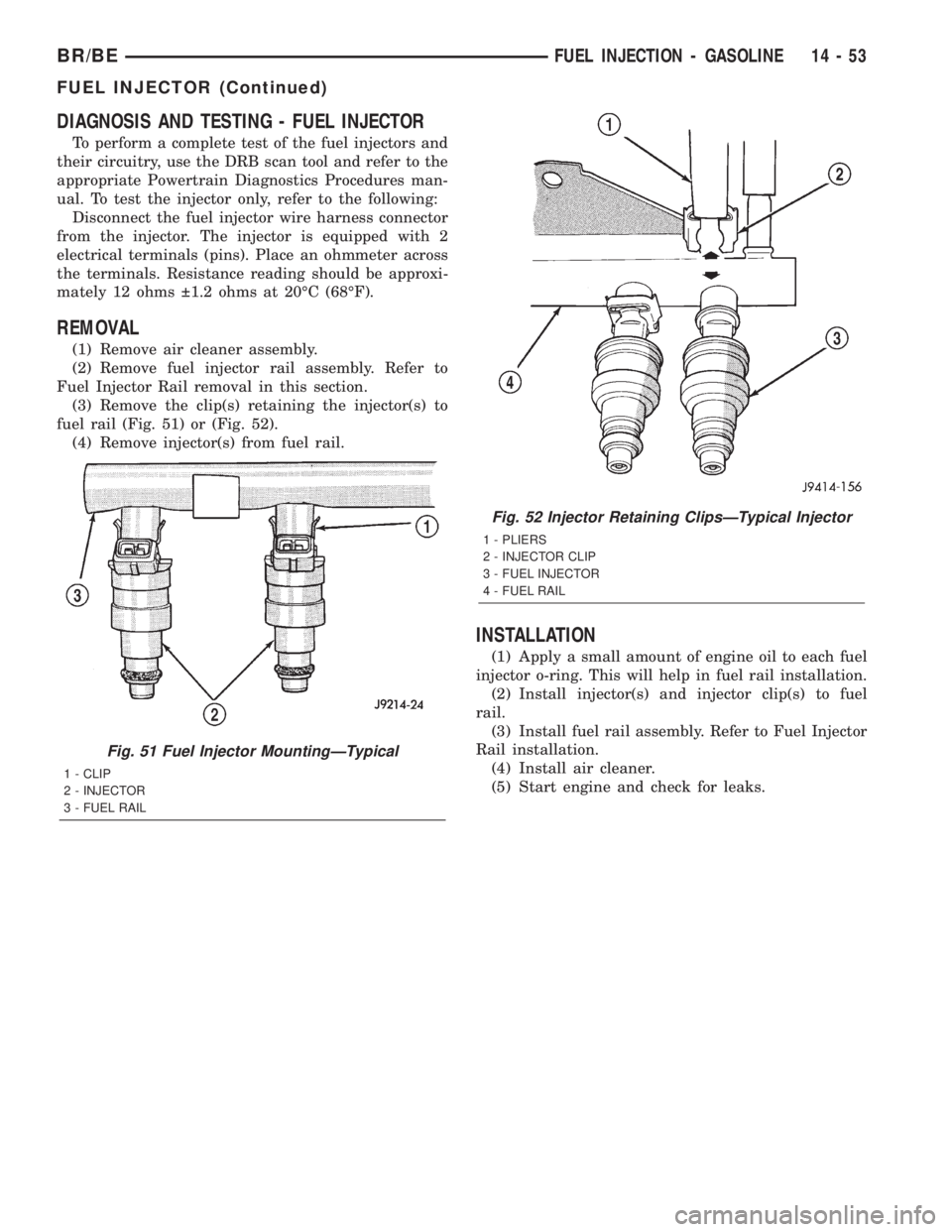
(3) Remove the clip(s) retaining the injector(s) to
fuel rail (Fig. 51) or (Fig. 52).
(4) Remove injector(s) from fuel rail.
INSTALLATION
(1) Apply a small amount of engine oil to each fuel
injector o-ring. This will help in fuel rail installation.
(2) Install injector(s) and injector clip(s) to fuel
rail.
(3) Install fuel rail assembly. Refer to Fuel Injector
Rail installation.
(4) Install air cleaner.
(5) Start engine and check for leaks.
Fig. 51 Fuel Injector MountingÐTypical
1 - CLIP
2 - INJECTOR
3 - FUEL RAIL
Fig. 52 Injector Retaining ClipsÐTypical Injector
1 - PLIERS
2 - INJECTOR CLIP
3 - FUEL INJECTOR
4 - FUEL RAIL
BR/BEFUEL INJECTION - GASOLINE 14 - 53
FUEL INJECTOR (Continued)
Page 1355 of 2255

Fig. 1 FUEL SYSTEM COMPONENTS - DIESEL
1 - ENGINE COOLANT TEMPERATURE (ECT) SENSOR 14 - FUEL SUPPLY LINE (LOW-PRESSURE, TO ENGINE)
2 - THROTTLE LEVER BELLCRANK AND APPS (ACCELERATOR
PEDAL POSITION SENSOR)15 - FUEL TRANSFER (LIFT) PUMP
3 - INTAKE MANIFOLD AIR HEATER/ELEMENTS 16 - OIL PRESSURE SENSOR
4 - HIGH-PRESSURE FUEL LINES 17 - FUEL FILTER/WATER SEPARATOR
5 - FUEL HEATER 18 - DRAIN TUBE
6 - FUEL PRESSURE TEST PORT 19 - WATER-IN-FUEL (WIF) SENSOR
7 - MAP (BOOST) SENSOR 20 - ENGINE CONTROL MODULE (ECM)
8 - FUEL INJECTORS 21 - FUEL PRESSURE TEST PORT
9 - FUEL INJECTOR CONNECTOR 22 - CAMSHAFT POSITION SENSOR (CMP)
10 - INTAKE AIR TEMPERATURE (IAT) SENSOR 23 - OVERFLOW VALVE
11 - FUEL DRAIN MANIFOLD 24 - FUEL INJECTION PUMP
12 - DRAIN VALVE 25 - FUEL HEATER TEMPERATURE SENSOR (THERMOSTAT)
13 - FUEL RETURN LINE (TO FUEL TANK)
14 - 56 FUEL DELIVERY - DIESELBR/BE
FUEL DELIVERY - DIESEL (Continued)
Page 1356 of 2255
DIAGNOSIS AND TESTING
DIAGNOSIS AND TESTING - FUEL SYSTEM AIR
LEAK VACUUM TEST
The proceeding test will determine if a fuel system
air leak exists at the engine. Air leaks will cause
hard starting and/or poor performance.
A hand-operated vacuum pump/gauge equipped
with a remote or built-on fluid container will be used.
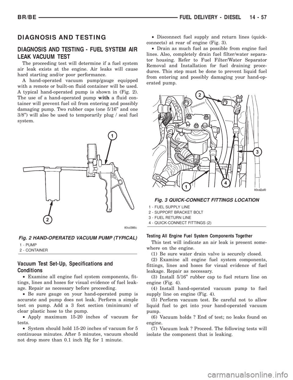
A typical hand-operated pump is shown in (Fig. 2).
The use of a hand-operated pumpwitha fluid con-
tainer will prevent fuel oil from entering and possibly
damaging pump. Two rubber caps (one 5/16º and one
3/8º) will also be used to temporarily plug / seal fuel
system.
Vacuum Test Set-Up, Specifications and
Conditions
²Examine all engine fuel system components, fit-
tings, lines and hoses for visual evidence of fuel leak-
age. Repair as necessary before proceeding.
²Be sure gauge on your hand-operated pump is
accurate and pump does not leak. Perform a simple
test on pump. Add a 3 foot section (minimum) of
clear plastic hose to the pump.
²Apply maximum 15-20 inches of vacuum for
tests.
²System should hold 15-20 inches of vacuum for 5
continuous minutes. After 5 minutes, vacuum should
not drop more than 0.1 inch Hg for 1 minute.²Disconnect fuel supply and return lines (quick-
connects) at rear of engine (Fig. 3).
²Drain as much fuel as possible from engine fuel
lines. Also, completely drain fuel filter/water separa-
tor housing. Refer to Fuel Filter/Water Separator
Removal and Installation for fuel draining proce-
dures. This step must be done to prevent liquid fuel
from entering and possibly damaging your hand-op-
erated pump.
Testing All Engine Fuel System Components Together
This test will indicate an air leak is present some-
where on the engine.
(1) Be sure water drain valve is securely closed.
(2) Examine all engine fuel system components,
fittings, lines and hoses for visual evidence of fuel
leakage. Repair as necessary.
(3) Install 5/16º rubber cap to fuel return line on
engine (Fig. 4).
(4) Install hand-operated vacuum pump to fuel
supply line on engine (Fig. 4).
(5) Perform vacuum test. Be careful not to allow
liquid fuel to get into your hand-operated vacuum
pump.
(6) Vacuum holds ? End of test; no leaks found on
engine.
(7) Vacuum leak ? Proceed. The following tests will
isolate the component that is leaking.
Fig. 2 HAND-OPERATED VACUUM PUMP (TYPICAL)
1 - PUMP
2 - CONTAINER
Fig. 3 QUICK-CONNECT FITTINGS LOCATION
1 - FUEL SUPPLY LINE
2 - SUPPORT BRACKET BOLT
3 - FUEL RETURN LINE
4 - QUICK-CONNECT FITTINGS (2)
BR/BEFUEL DELIVERY - DIESEL 14 - 57
Page 1360 of 2255
STANDARD PROCEDURE
STANDARD PROCEDURES - WATER DRAINING
AT FUEL FILTER
Refer to Fuel Filter/Water Separator removal/in-
stallation for procedures.
STANDARD PROCEDURES - CLEANING FUEL
SYSTEM PARTS
CAUTION: Cleanliness cannot be overemphasized
when handling or replacing diesel fuel system com-
ponents. This especially includes the fuel injectors,
high-pressure fuel lines and fuel injection pump.
Very tight tolerances are used with these parts. Dirt
contamination could cause rapid part wear and pos-
sible plugging of fuel injector nozzle tip holes. This
in turn could lead to possible engine misfire.
Always wash/clean any fuel system component
thoroughly before disassembly and then air dry.
Cap or cover any open part after disassembly.
Before assembly, examine each part for dirt, grease
or other contaminants and clean if necessary. When
installing new parts, lubricate them with clean
engine oil or clean diesel fuel only.
STANDARD PROCEDURE - AIR BLEED
A certain amount of air becomes trapped in the
fuel system when fuel system components on the
supply and/or high-pressure side are serviced or
replaced. Primary air bleeding is accomplished using
the electric fuel transfer (lift) pump. If the vehicle
has been allowed to run completely out of fuel, the
fuel injectors must also be bled as the fuel injection
pumpis notself-bleeding (priming).
Servicing or replacing components on the fuel
return side will not require air bleeding.
WARNING: DO NOT BLEED AIR FROM THE FUEL
SYSTEM OF A HOT ENGINE.
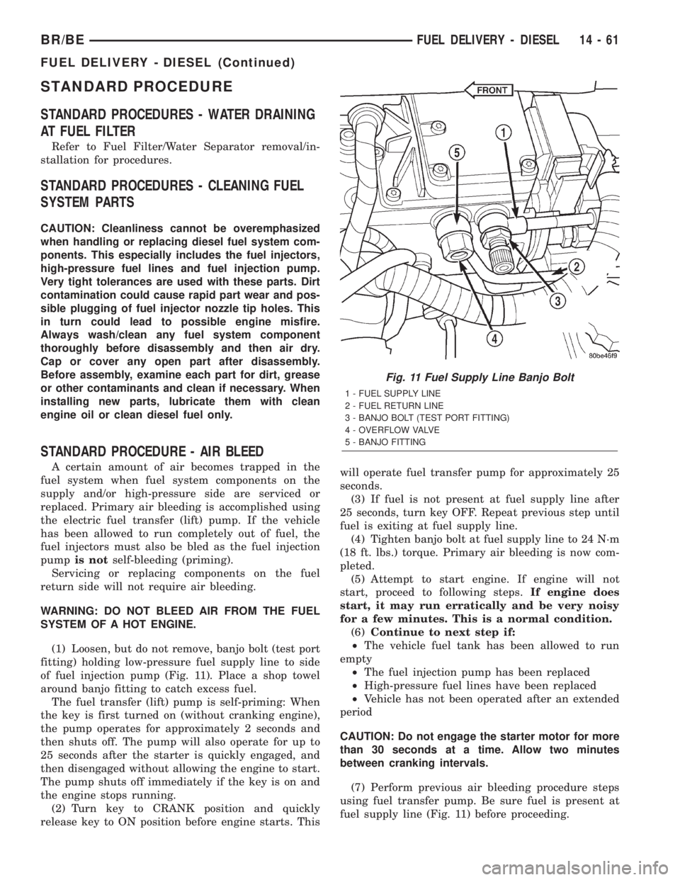
(1) Loosen, but do not remove, banjo bolt (test port
fitting) holding low-pressure fuel supply line to side
of fuel injection pump (Fig. 11). Place a shop towel
around banjo fitting to catch excess fuel.
The fuel transfer (lift) pump is self-priming: When
the key is first turned on (without cranking engine),
the pump operates for approximately 2 seconds and
then shuts off. The pump will also operate for up to
25 seconds after the starter is quickly engaged, and
then disengaged without allowing the engine to start.
The pump shuts off immediately if the key is on and
the engine stops running.
(2) Turn key to CRANK position and quickly
release key to ON position before engine starts. Thiswill operate fuel transfer pump for approximately 25
seconds.
(3) If fuel is not present at fuel supply line after
25 seconds, turn key OFF. Repeat previous step until
fuel is exiting at fuel supply line.
(4) Tighten banjo bolt at fuel supply line to 24 N´m
(18 ft. lbs.) torque. Primary air bleeding is now com-
pleted.
(5) Attempt to start engine. If engine will not
start, proceed to following steps.If engine does
start, it may run erratically and be very noisy
for a few minutes. This is a normal condition.
(6)Continue to next step if:
²The vehicle fuel tank has been allowed to run
empty
²The fuel injection pump has been replaced
²High-pressure fuel lines have been replaced
²Vehicle has not been operated after an extended
period
CAUTION: Do not engage the starter motor for more
than 30 seconds at a time. Allow two minutes
between cranking intervals.
(7) Perform previous air bleeding procedure steps
using fuel transfer pump. Be sure fuel is present at
fuel supply line (Fig. 11) before proceeding.
Fig. 11 Fuel Supply Line Banjo Bolt
1 - FUEL SUPPLY LINE
2 - FUEL RETURN LINE
3 - BANJO BOLT (TEST PORT FITTING)
4 - OVERFLOW VALVE
5 - BANJO FITTING
BR/BEFUEL DELIVERY - DIESEL 14 - 61
FUEL DELIVERY - DIESEL (Continued)
Page 1364 of 2255
(c) Check condition of o-ring.
(d) Inspect the 2 WIF sensor probes. Carefully
clean contaminants from sensor probes with a cloth
if necessary. Replace sensor if probes are covered
with contaminants and will not clean up.
(7)Fuel Heater Element Replacement:The
heater element is located in the fuel filter housing
(Fig. 15).
(a) Remove fuel filter. See previous steps.
(b) Disconnect electrical connector from fuel tem-
perature sensor housing at side of fuel filter hous-
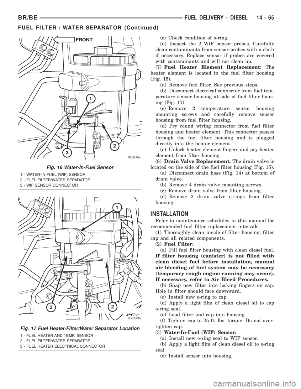
ing (Fig. 17).
(c) Remove 2 temperature sensor housing
mounting screws and carefully remove sensor
housing from fuel filter housing.
(d) Pry round wiring connector from fuel filter
housing and heater element. This connector passes
through the fuel filter housing and is plugged
directly into the heater element.
(e) Unlock heater element fingers and pry heater
element from filter housing.
(8)Drain Valve Replacement:The drain valve is
located on the side of the fuel filter housing (Fig. 15).
(a) Disconnect drain hose (Fig. 14) at bottom of
drain valve.
(b) Remove 4 drain valve mounting screws.
(c) Remove drain valve from filter housing.
(d) Remove 2 drain valve o-rings from filter
housing.
INSTALLATION
Refer to maintenance schedules in this manual for
recommended fuel filter replacement intervals.
(1) Thoroughly clean inside of filter housing, filter
cap and all related components.
(2)Fuel Filter:
(a) Fill fuel filter housing with clean diesel fuel.
If filter housing (canister) is not filled with
clean diesel fuel before installation, manual
air bleeding of fuel system may be necessary
(temporary rough engine running may occur).
If necessary, refer to Air Bleed Procedures.
(b) Snap new filter into locking fingers on cap.
Hole in filter should face downward.
(c) Install new o-ring to cap.
(d) Apply a light film of clean diesel oil to cap
o-ring seal.
(e) Load filter and cap into housing.
(f) Tighten cap to 25 ft. lbs. torque. Do not over-
tighten cap.
(3)Water-In-Fuel (WIF) Sensor:
(a) Install new o-ring seal to WIF sensor.
(b) Apply a light film of clean diesel oil to o-ring
seal.
(c) Install sensor into housing.
Fig. 16 Water-In-Fuel Sensor
1 - WATER-IN-FUEL (WIF) SENSOR
2 - FUEL FILTER/WATER SEPARATOR
3 - WIF SENSOR CONNECTOR
Fig. 17 Fuel Heater/Filter/Water Separator Location
1 - FUEL HEATER AND TEMP. SENSOR
2 - FUEL FILTER/WATER SEPARATOR
3 - FUEL HEATER ELECTRICAL CONNECTOR
BR/BEFUEL DELIVERY - DIESEL 14 - 65
FUEL FILTER / WATER SEPARATOR (Continued)
Page 1365 of 2255
(d) Tighten sensor to 2±3 N´m (15±20 in. lbs.)
torque.
(e) Connect electrical connector to WIF sensor.
(f) Install fuel filter. Refer to previous steps.
(4)Fuel Heater Element:
(a) Do not install fuel filter until heater element
is installed.
(b) Position heater element into filter housing
(fingers downward). Lock fingers into housing.
(c) Install new o-ring to electrical connector
(where connector passes through filter housing).
Apply a light film of clean diesel oil to o-ring seal.
Press this connector into filter housing until it
snaps into heater element.
(d) Install temperature sensor housing and 2
mounting screws to fuel filter housing.
(e) Connect electrical connector.
(f) Install fuel filter. Refer to previous steps.
(5)Drain Valve:
(a) Install 2 new o-rings to valve and filter hous-
ing.
(b) Apply a light film of clean diesel oil to both
seals.
(c) Position valve to filter housing.
(d) Install 4 mounting screws and tighten to 3±5
N´m (30±40 in. lbs.) torque.
(e) Connect drain hose to drain valve.
(f) Install fuel filter. Refer to previous steps.
(6) Start engine and check for leaks.
FUEL HEATER
DESCRIPTION
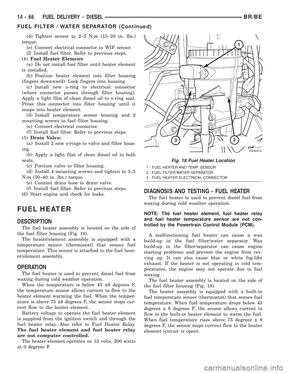
The fuel heater assembly is located on the side of
the fuel filter housing (Fig. 18).
The heater/element assembly is equipped with a
temperature sensor (thermostat) that senses fuel
temperature. This sensor is attached to the fuel heat-
er/element assembly.
OPERATION
The fuel heater is used to prevent diesel fuel from
waxing during cold weather operation.
When the temperature is below 45 8 degrees F,
the temperature sensor allows current to flow to the
heater element warming the fuel. When the temper-
ature is above 75 8 degrees F, the sensor stops cur-
rent flow to the heater element.
Battery voltage to operate the fuel heater element
is supplied from the ignition switch and through the
fuel heater relay. Also refer to Fuel Heater Relay.
The fuel heater element and fuel heater relay
are not computer controlled.
The heater element operates on 12 volts, 300 watts
at 0 degrees F.
DIAGNOSIS AND TESTING - FUEL HEATER
The fuel heater is used to prevent diesel fuel from
waxing during cold weather operation.
NOTE: The fuel heater element, fuel heater relay
and fuel heater temperature sensor are not con-
trolled by the Powertrain Control Module (PCM).
A malfunctioning fuel heater can cause a wax
build-up in the fuel filter/water separator. Wax
build-up in the filter/separator can cause engine
starting problems and prevent the engine from rev-
ving up. It can also cause blue or white fog-like
exhaust. If the heater is not operating in cold tem-
peratures, the engine may not operate due to fuel
waxing.
The fuel heater assembly is located on the side of
the fuel filter housing (Fig. 19).
The heater assembly is equipped with a built-in
fuel temperature sensor (thermostat) that senses fuel
temperature. When fuel temperature drops below 45
degrees 8 degrees F, the sensor allows current to
flow to the built-in heater element to warm the fuel.
When fuel temperature rises above 75 degrees 8
degrees F, the sensor stops current flow to the heater
element (circuit is open).
Fig. 18 Fuel Heater Location
1 - FUEL HEATER AND TEMP. SENSOR
2 - FUEL FILTER/WATER SEPARATOR
3 - FUEL HEATER ELECTRICAL CONNECTOR
14 - 66 FUEL DELIVERY - DIESELBR/BE
FUEL FILTER / WATER SEPARATOR (Continued)
Page 1371 of 2255
(1) Remove hose clamp and crankcase vent hose at
crankcase breather (Fig. 26). Remove crankcase
breather from gear cover. Breather threads into
cover.
(2) Remove injection pump nut and washer (Fig.
27). Locate keyway behind washer.
(3) Be sure keyway aligning fuel injection pump
shaft to injection pump gear is in proper position and
pump gear has not slipped on pump shaft.
The following steps will require removing timing
gear cover to gain access to timing gears. Refer to
Group 9, Engines for procedures.
(4) Use a T-type puller to separate injection pump
gear from pump shaft.
(5) Be sure keyway has been installed with arrow
pointed torearof pump (Fig. 28).
(6)Pump timing has been calibrated to pump
keyway. Be sure 3±digit number on pump key-
way (Fig. 28) matches 3±digit number on fuel
injection pump data plate. Plate is located on
side of injection pump (Fig. 29). Twenty±one dif-
ferent calibrated keyways/pumps are available.
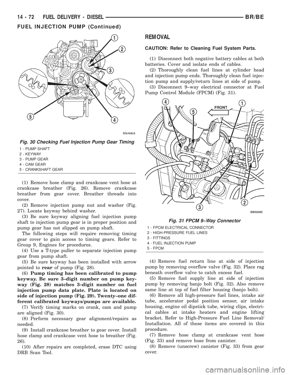
(7) Verify timing marks on crank, cam and pump
are aligned (Fig. 30).
(8) Perform necessary gear alignment/repairs as
needed.
(9) Install crankcase breather to gear cover. Install
hose clamp and crankcase vent hose to breather (Fig.
26).
(10) After repairs are completed, erase DTC using
DRB Scan Tool.
REMOVAL
CAUTION: Refer to Cleaning Fuel System Parts.
(1) Disconnect both negative battery cables at both
batteries. Cover and isolate ends of cables.
(2) Thoroughly clean fuel lines at cylinder head
and injection pump ends. Thoroughly clean fuel injec-
tion pump and supply/return lines at side of pump.
(3) Disconnect 9±way electrical connector at Fuel
Pump Control Module (FPCM) (Fig. 31).
(4) Remove fuel return line at side of injection
pump by removing overflow valve (Fig. 32). Place rag
beneath overflow valve to catch excess fuel.
(5) Remove fuel supply line at side of injection
pump by removing banjo bolt (Fig. 32). Also remove
same line at top of fuel filter housing (banjo bolt).
(6) Remove all high-pressure fuel lines, intake air
tube, accelerator pedal position sensor, air intake
housing, engine oil dipstick tube, wiring clips, electri-
cal cables at intake heaters and engine lifting
bracket. Refer to High-Pressure Fuel Line Removal/
Installation. All of these items are covered in this
procedure.
(7) Remove hose clamp at crankcase vent hose
(Fig. 33) and remove hose from canister.
(8) Remove (unscrew) canister (Fig. 33) from gear
cover.
Fig. 30 Checking Fuel Injection Pump Gear Timing
1 - PUMP SHAFT
2 - KEYWAY
3 - PUMP GEAR
4 - CAM GEAR
5 - CRANKSHAFT GEAR
Fig. 31 FPCM 9±Way Connector
1 - FPCM ELECTRICAL CONNECTOR
2 - HIGH-PRESSURE FUEL LINES
3 - FITTINGS
4 - FUEL INJECTION PUMP
5 - FPCM
14 - 72 FUEL DELIVERY - DIESELBR/BE
FUEL INJECTION PUMP (Continued)