2002 DODGE RAM oil
[x] Cancel search: oilPage 1432 of 2255
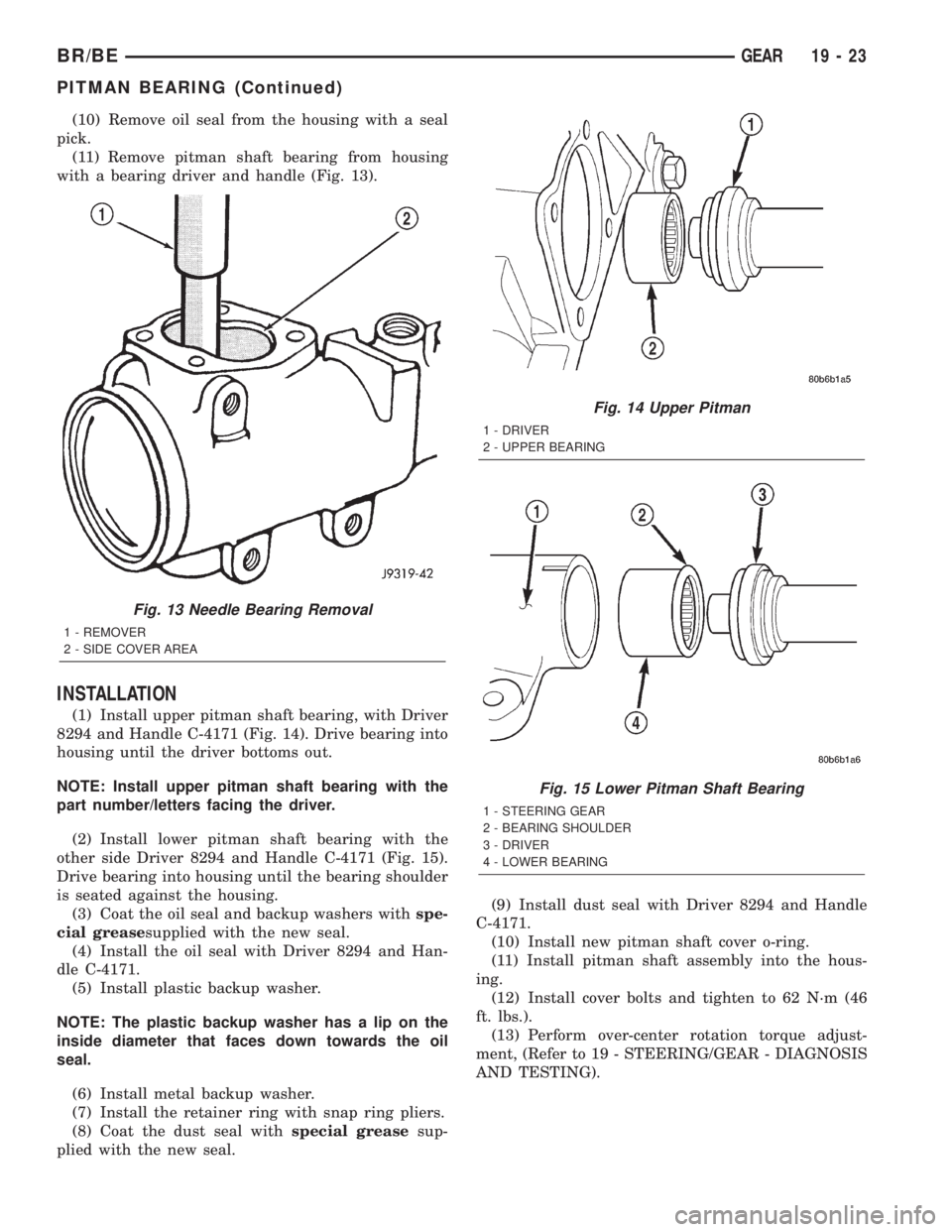
(10) Remove oil seal from the housing with a seal
pick.
(11) Remove pitman shaft bearing from housing
with a bearing driver and handle (Fig. 13).
INSTALLATION
(1) Install upper pitman shaft bearing, with Driver
8294 and Handle C-4171 (Fig. 14). Drive bearing into
housing until the driver bottoms out.
NOTE: Install upper pitman shaft bearing with the
part number/letters facing the driver.
(2) Install lower pitman shaft bearing with the
other side Driver 8294 and Handle C-4171 (Fig. 15).
Drive bearing into housing until the bearing shoulder
is seated against the housing.
(3) Coat the oil seal and backup washers withspe-
cial greasesupplied with the new seal.
(4) Install the oil seal with Driver 8294 and Han-
dle C-4171.
(5) Install plastic backup washer.
NOTE: The plastic backup washer has a lip on the
inside diameter that faces down towards the oil
seal.
(6) Install metal backup washer.
(7) Install the retainer ring with snap ring pliers.
(8) Coat the dust seal withspecial greasesup-
plied with the new seal.(9) Install dust seal with Driver 8294 and Handle
C-4171.
(10) Install new pitman shaft cover o-ring.
(11) Install pitman shaft assembly into the hous-
ing.
(12) Install cover bolts and tighten to 62 N´m (46
ft. lbs.).
(13) Perform over-center rotation torque adjust-
ment, (Refer to 19 - STEERING/GEAR - DIAGNOSIS
AND TESTING).
Fig. 13 Needle Bearing Removal
1 - REMOVER
2 - SIDE COVER AREA
Fig. 14 Upper Pitman
1 - DRIVER
2 - UPPER BEARING
Fig. 15 Lower Pitman Shaft Bearing
1 - STEERING GEAR
2 - BEARING SHOULDER
3 - DRIVER
4 - LOWER BEARING
BR/BEGEAR 19 - 23
PITMAN BEARING (Continued)
Page 1433 of 2255
PITMAN SHAFT
REMOVAL
(1) Clean exposed end of pitman shaft and housing
with a wire brush.
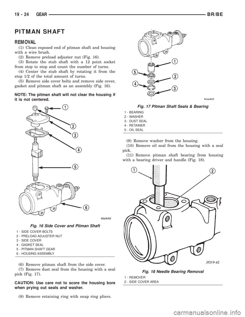
(2) Remove preload adjuster nut (Fig. 16).
(3) Rotate the stub shaft with a 12 point socket
from stop to stop and count the number of turns.
(4) Center the stub shaft by rotating it from the
stop 1/2 of the total amount of turns.
(5) Remove side cover bolts and remove side cover,
gasket and pitman shaft as an assembly (Fig. 16).
NOTE: The pitman shaft will not clear the housing if
it is not centered.
(6) Remove pitman shaft from the side cover.
(7) Remove dust seal from the housing with a seal
pick (Fig. 17).
CAUTION: Use care not to score the housing bore
when prying out seals and washer.
(8) Remove retaining ring with snap ring pliers.(9) Remove washer from the housing.
(10) Remove oil seal from the housing with a seal
pick.
(11) Remove pitman shaft bearing from housing
with a bearing driver and handle (Fig. 18).
Fig. 16 Side Cover and Pitman Shaft
1 - SIDE COVER BOLTS
2 - PRELOAD ADJUSTER NUT
3 - SIDE COVER
4 - GASKET SEAL
5 - PITMAN SHAFT GEAR
6 - HOUSING ASSEMBLY
Fig. 17 Pitman Shaft Seals & Bearing
1 - BEARING
2 - WASHER
3 - DUST SEAL
4 - RETAINER
5 - OIL SEAL
Fig. 18 Needle Bearing Removal
1 - REMOVER
2 - SIDE COVER AREA
19 - 24 GEARBR/BE
Page 1434 of 2255
INSTALLATION
(1) Install pitman shaft bearing into housing with
a bearing driver and handle.
(2) Coat the oil seal and washer withspecial
greasesupplied with the new seal.
(3) Install the oil seal with a driver and handle.
(4) Install backup washer.
(5) Install the retainer ring with snap ring pliers.
(6) Coat the dust seal withspecial greasesup-
plied with the new seal.
(7) Install dust seal with a driver and handle.
(8) Install pitman shaft to side cover by screwing
shaft in until it fully seats to side cover.
(9) Install preload adjuster nut.Do not tighten
nut until after Over-Center Rotation Torque
adjustment has been made.
(10) Install gasket to side cover and bend tabs
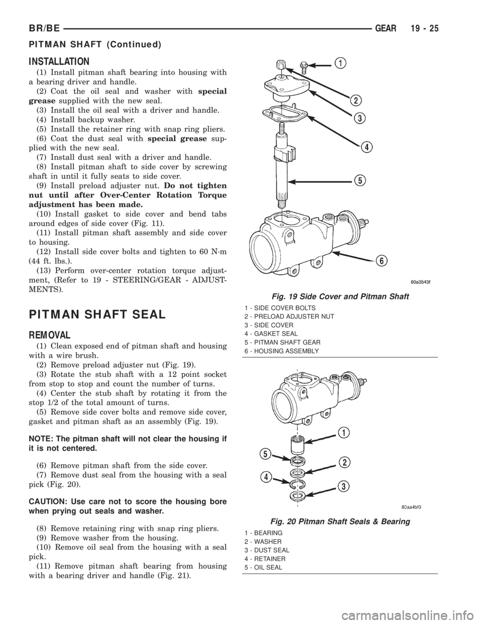
around edges of side cover (Fig. 11).
(11) Install pitman shaft assembly and side cover
to housing.
(12) Install side cover bolts and tighten to 60 N´m
(44 ft. lbs.).
(13) Perform over-center rotation torque adjust-
ment, (Refer to 19 - STEERING/GEAR - ADJUST-
MENTS).
PITMAN SHAFT SEAL
REMOVAL
(1) Clean exposed end of pitman shaft and housing
with a wire brush.
(2) Remove preload adjuster nut (Fig. 19).
(3) Rotate the stub shaft with a 12 point socket
from stop to stop and count the number of turns.
(4) Center the stub shaft by rotating it from the
stop 1/2 of the total amount of turns.
(5) Remove side cover bolts and remove side cover,
gasket and pitman shaft as an assembly (Fig. 19).
NOTE: The pitman shaft will not clear the housing if
it is not centered.
(6) Remove pitman shaft from the side cover.
(7) Remove dust seal from the housing with a seal
pick (Fig. 20).
CAUTION: Use care not to score the housing bore
when prying out seals and washer.
(8) Remove retaining ring with snap ring pliers.
(9) Remove washer from the housing.
(10) Remove oil seal from the housing with a seal
pick.
(11) Remove pitman shaft bearing from housing
with a bearing driver and handle (Fig. 21).
Fig. 19 Side Cover and Pitman Shaft
1 - SIDE COVER BOLTS
2 - PRELOAD ADJUSTER NUT
3 - SIDE COVER
4 - GASKET SEAL
5 - PITMAN SHAFT GEAR
6 - HOUSING ASSEMBLY
Fig. 20 Pitman Shaft Seals & Bearing
1 - BEARING
2 - WASHER
3 - DUST SEAL
4 - RETAINER
5 - OIL SEAL
BR/BEGEAR 19 - 25
PITMAN SHAFT (Continued)
Page 1435 of 2255
INSTALLATION
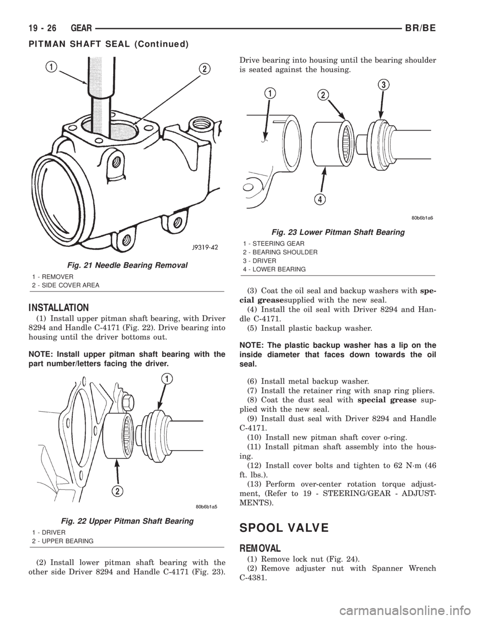
(1) Install upper pitman shaft bearing, with Driver
8294 and Handle C-4171 (Fig. 22). Drive bearing into
housing until the driver bottoms out.
NOTE: Install upper pitman shaft bearing with the
part number/letters facing the driver.
(2) Install lower pitman shaft bearing with the
other side Driver 8294 and Handle C-4171 (Fig. 23).Drive bearing into housing until the bearing shoulder
is seated against the housing.
(3) Coat the oil seal and backup washers withspe-
cial greasesupplied with the new seal.
(4) Install the oil seal with Driver 8294 and Han-
dle C-4171.
(5) Install plastic backup washer.
NOTE: The plastic backup washer has a lip on the
inside diameter that faces down towards the oil
seal.
(6) Install metal backup washer.
(7) Install the retainer ring with snap ring pliers.
(8) Coat the dust seal withspecial greasesup-
plied with the new seal.
(9) Install dust seal with Driver 8294 and Handle
C-4171.
(10) Install new pitman shaft cover o-ring.
(11) Install pitman shaft assembly into the hous-
ing.
(12) Install cover bolts and tighten to 62 N´m (46
ft. lbs.).
(13) Perform over-center rotation torque adjust-
ment, (Refer to 19 - STEERING/GEAR - ADJUST-
MENTS).
SPOOL VALVE
REMOVAL
(1) Remove lock nut (Fig. 24).
(2) Remove adjuster nut with Spanner Wrench
C-4381.
Fig. 21 Needle Bearing Removal
1 - REMOVER
2 - SIDE COVER AREA
Fig. 22 Upper Pitman Shaft Bearing
1 - DRIVER
2 - UPPER BEARING
Fig. 23 Lower Pitman Shaft Bearing
1 - STEERING GEAR
2 - BEARING SHOULDER
3 - DRIVER
4 - LOWER BEARING
19 - 26 GEARBR/BE
PITMAN SHAFT SEAL (Continued)
Page 1442 of 2255
PUMP
TABLE OF CONTENTS
page page
PUMP
DESCRIPTION.........................33
OPERATION...........................33
DIAGNOSIS AND TESTING - PUMP LEAKAGE . 33
STANDARD PROCEDURE
STANDARD PROCEDURE - POWER
STEERING PUMP - INITIAL OPERATION....33
STANDARD PROCEDURE - FLUSHING
POWER STEERING SYSTEM............34
REMOVAL
REMOVAL - GASOLINE ENGINE..........35
REMOVAL - DIESEL ENGINE............36
INSTALLATION
INSTALLATION - GASOLINE ENGINE......37INSTALLATION - DIESEL ENGINE.........37
SPECIAL TOOLS
POWER STEERING PUMP..............38
PULLEY
REMOVAL.............................38
INSTALLATION.........................39
HOSES - PRESSURE
DESCRIPTION.........................39
OPERATION...........................39
HOSES - RETURN
DESCRIPTION.........................39
OPERATION...........................39
PUMP
DESCRIPTION
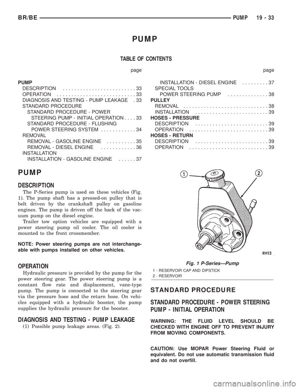
The P-Series pump is used on these vehicles (Fig.
1). The pump shaft has a pressed-on pulley that is
belt driven by the crankshaft pulley on gasoline
engines. The pump is driven off the back of the vac-
uum pump on the diesel engine.
Trailer tow option vehicles are equipped with a
power steering pump oil cooler. The oil cooler is
mounted to the front crossmember.
NOTE: Power steering pumps are not interchange-
able with pumps installed on other vehicles.
OPERATION
Hydraulic pressure is provided by the pump for the
power steering gear. The power steering pump is a
constant flow rate and displacement, vane-type
pump. The pump is connected to the steering gear
via the pressure hose and the return hose. On vehi-
cles equipped with a hydraulic booster, the pump
supplies the hydraulic pressure for the booster.
DIAGNOSIS AND TESTING - PUMP LEAKAGE
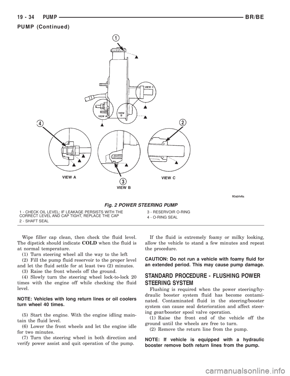
(1) Possible pump leakage areas. (Fig. 2).
STANDARD PROCEDURE
STANDARD PROCEDURE - POWER STEERING
PUMP - INITIAL OPERATION
WARNING: THE FLUID LEVEL SHOULD BE
CHECKED WITH ENGINE OFF TO PREVENT INJURY
FROM MOVING COMPONENTS.
CAUTION: Use MOPAR Power Steering Fluid or
equivalent. Do not use automatic transmission fluid
and do not overfill.
Fig. 1 P-SeriesÐPump
1 - RESERVOIR CAP AND DIPSTICK
2 - RESERVOIR
BR/BEPUMP 19 - 33
Page 1443 of 2255
Wipe filler cap clean, then check the fluid level.
The dipstick should indicateCOLDwhen the fluid is
at normal temperature.
(1) Turn steering wheel all the way to the left
(2) Fill the pump fluid reservoir to the proper level
and let the fluid settle for at least two (2) minutes.
(3) Raise the front wheels off the ground.
(4) Slowly turn the steering wheel lock-to-lock 20
times with the engine off while checking the fluid
level.
NOTE: Vehicles with long return lines or oil coolers
turn wheel 40 times.
(5) Start the engine. With the engine idling main-
tain the fluid level.
(6) Lower the front wheels and let the engine idle
for two minutes.
(7) Turn the steering wheel in both direction and
verify power assist and quit operation of the pump.If the fluid is extremely foamy or milky looking,
allow the vehicle to stand a few minutes and repeat
the procedure.
CAUTION: Do not run a vehicle with foamy fluid for
an extended period. This may cause pump damage.
STANDARD PROCEDURE - FLUSHING POWER
STEERING SYSTEM
Flushing is required when the power steering/hy-
draulic booster system fluid has become contami-
nated. Contaminated fluid in the steering/booster
system can cause seal deterioration and affect steer-
ing gear/booster spool valve operation.
(1) Raise the front end of the vehicle off the
ground until the wheels are free to turn.
(2) Remove the return line from the pump.
NOTE: If vehicle is equipped with a hydraulic
booster remove both return lines from the pump.
Fig. 2 POWER STEERING PUMP
1 - CHECK OIL LEVEL; IF LEAKAGE PERSISTS WITH THE
CORRECT LEVEL AND CAP TIGHT, REPLACE THE CAP
2 - SHAFT SEAL3 - RESERVOIR O-RING
4 - O-RING SEAL
19 - 34 PUMPBR/BE
PUMP (Continued)
Page 1445 of 2255
REMOVAL - DIESEL ENGINE
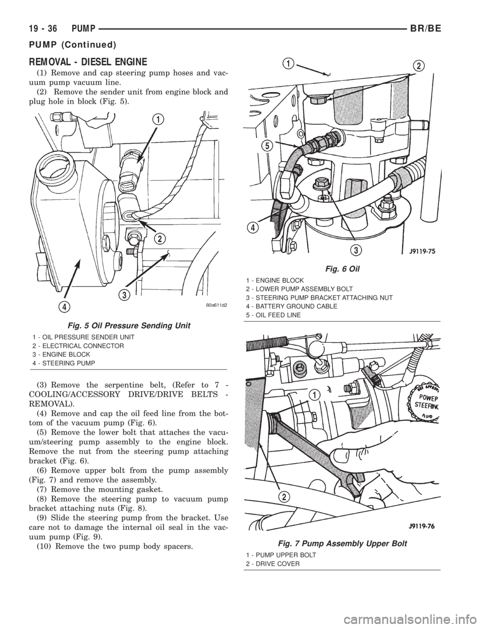
(1) Remove and cap steering pump hoses and vac-
uum pump vacuum line.
(2) Remove the sender unit from engine block and
plug hole in block (Fig. 5).
(3) Remove the serpentine belt, (Refer to 7 -
COOLING/ACCESSORY DRIVE/DRIVE BELTS -
REMOVAL).
(4) Remove and cap the oil feed line from the bot-
tom of the vacuum pump (Fig. 6).
(5) Remove the lower bolt that attaches the vacu-
um/steering pump assembly to the engine block.
Remove the nut from the steering pump attaching
bracket (Fig. 6).
(6) Remove upper bolt from the pump assembly
(Fig. 7) and remove the assembly.
(7) Remove the mounting gasket.
(8) Remove the steering pump to vacuum pump
bracket attaching nuts (Fig. 8).
(9) Slide the steering pump from the bracket. Use
care not to damage the internal oil seal in the vac-
uum pump (Fig. 9).
(10) Remove the two pump body spacers.
Fig. 5 Oil Pressure Sending Unit
1 - OIL PRESSURE SENDER UNIT
2 - ELECTRICAL CONNECTOR
3 - ENGINE BLOCK
4 - STEERING PUMP
Fig. 6 Oil
1 - ENGINE BLOCK
2 - LOWER PUMP ASSEMBLY BOLT
3 - STEERING PUMP BRACKET ATTACHING NUT
4 - BATTERY GROUND CABLE
5 - OIL FEED LINE
Fig. 7 Pump Assembly Upper Bolt
1 - PUMP UPPER BOLT
2 - DRIVE COVER
19 - 36 PUMPBR/BE
PUMP (Continued)
Page 1446 of 2255
INSTALLATION
INSTALLATION - GASOLINE ENGINE
(1) Install the front pump bracket and tighten
bolts to 47 N´m (35 ft. lbs.). On 8.0L engine install
rear pump bracket and tighten nut to 47 N´m (35 ft.
lbs.), tighten bolts to 24 N´m (18 ft. lbs.).
(2) Install the pump pulley with Installer
C-4063±B, (Refer to 19 - STEERING/PUMP/PULLEY
- INSTALLATION).
(3) Install steering pump assembly on the engine
block. Install the upper stud and bolt in bracket.
(4) Pivot the pump down past the coolant tube and
install the lower bolts in bracket.
(5) Tighten the bolts and nut to 41 N´m (30 ft.
lbs.).
(6) Connect the hoses to the pump.
(7) Install the serpentine drive belt, (Refer to 7 -
COOLING/ACCESSORY DRIVE/DRIVE BELTS -
INSTALLATION), (Refer to 7 - COOLING/ACCES-
SORY DRIVE/DRIVE BELTS - INSTALLATION).
(8) Fill the reservoir with power steering fluid,
(Refer to 19 - STEERING/PUMP - STANDARD PRO-
CEDURE).
INSTALLATION - DIESEL ENGINE
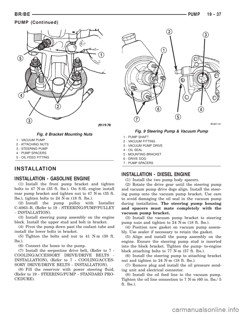
(1) Install the two pump body spacers.
(2) Rotate the drive gear until the steering pump
and vacuum pump drive dogs align. Install the steer-
ing pump onto the vacuum pump bracket. Use care
to avoid damaging the oil seal in the vacuum pump
during installation.The steering pump housing
and spacers must mate completely with the
vacuum pump bracket.
(3) Install the vacuum pump bracket to steering
pump nuts and tighten to 24 N´m (18 ft. lbs.).
(4) Position new gasket on vacuum pump assem-
bly. Use sealer if necessary to retain the gasket.
(5) Align and install the pump assembly on the
engine. Ensure the steering pump stud is inserted
into the block bracket. Tighten the pump- to-engine
block attaching bolts to 77 N´m (57 ft. lbs.).
(6) Install the steering pump to attaching bracket
nut and tighten to 24 N´m (18 ft. lbs.).
(7) Remove plug and install the oil pressure send-
ing unit and electrical connector.
(8) Install the oil feed line to the vacuum pump.
Tighten the oil line connection to 7 N´m (60 in. lbs./ 5
ft. lbs.).
Fig. 8 Bracket Mounting Nuts
1 - VACUUM PUMP
2 - ATTACHING NUTS
3 - STEERING PUMP
4 - PUMP SPACERS
5 - OIL FEED FITTING
Fig. 9 Steering Pump & Vacuum Pump
1 - PUMP SHAFT
2 - VACUUM FITTING
3 - VACUUM PUMP DRIVE
4 - OIL SEAL
5 - MOUNTING BRACKET
6 - DRIVE DOG
7 - PUMP SPACERS
BR/BEPUMP 19 - 37
PUMP (Continued)