2002 DODGE RAM oil
[x] Cancel search: oilPage 1391 of 2255
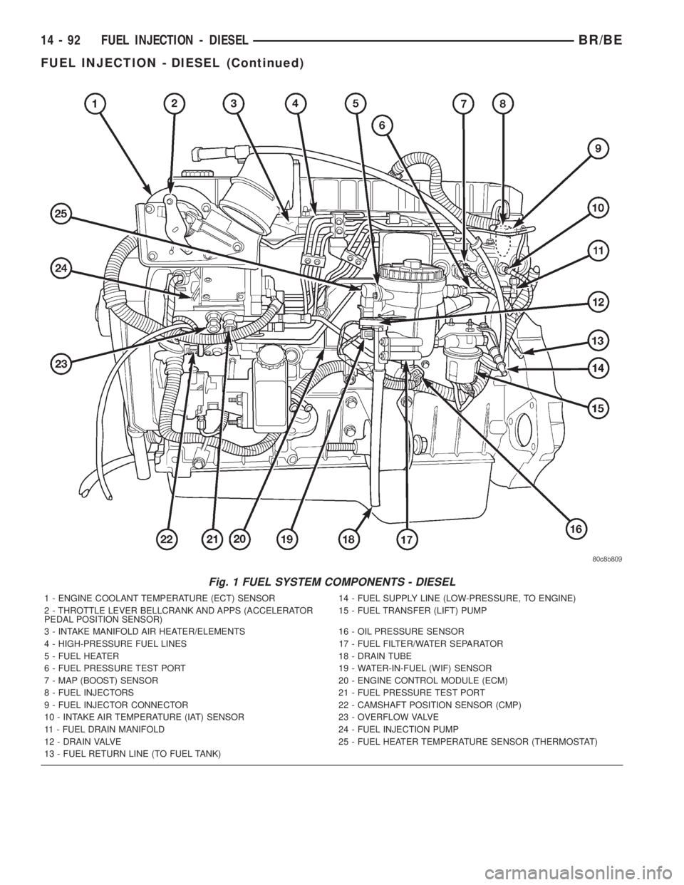
Fig. 1 FUEL SYSTEM COMPONENTS - DIESEL
1 - ENGINE COOLANT TEMPERATURE (ECT) SENSOR 14 - FUEL SUPPLY LINE (LOW-PRESSURE, TO ENGINE)
2 - THROTTLE LEVER BELLCRANK AND APPS (ACCELERATOR
PEDAL POSITION SENSOR)15 - FUEL TRANSFER (LIFT) PUMP
3 - INTAKE MANIFOLD AIR HEATER/ELEMENTS 16 - OIL PRESSURE SENSOR
4 - HIGH-PRESSURE FUEL LINES 17 - FUEL FILTER/WATER SEPARATOR
5 - FUEL HEATER 18 - DRAIN TUBE
6 - FUEL PRESSURE TEST PORT 19 - WATER-IN-FUEL (WIF) SENSOR
7 - MAP (BOOST) SENSOR 20 - ENGINE CONTROL MODULE (ECM)
8 - FUEL INJECTORS 21 - FUEL PRESSURE TEST PORT
9 - FUEL INJECTOR CONNECTOR 22 - CAMSHAFT POSITION SENSOR (CMP)
10 - INTAKE AIR TEMPERATURE (IAT) SENSOR 23 - OVERFLOW VALVE
11 - FUEL DRAIN MANIFOLD 24 - FUEL INJECTION PUMP
12 - DRAIN VALVE 25 - FUEL HEATER TEMPERATURE SENSOR (THERMOSTAT)
13 - FUEL RETURN LINE (TO FUEL TANK)
14 - 92 FUEL INJECTION - DIESELBR/BE
FUEL INJECTION - DIESEL (Continued)
Page 1392 of 2255
DIAGNOSIS AND TESTING - BOOST PRESSURE
Two pressure gauges attached at two different
points are required for this test.(1) Obtain two 6828 fuel pressure test gauges
(equivalent gauges are OK).Gauge Consistency
Test:Connect the gauges together to a common pres-
sure source and verify pressure consistency of both
gauges. Do this consistency test at approximately 206
kPa (30 psi). If pressures are different, they can still
be used for test. Note and record differences in pres-
sures before testing. Make adjustments as necessary.
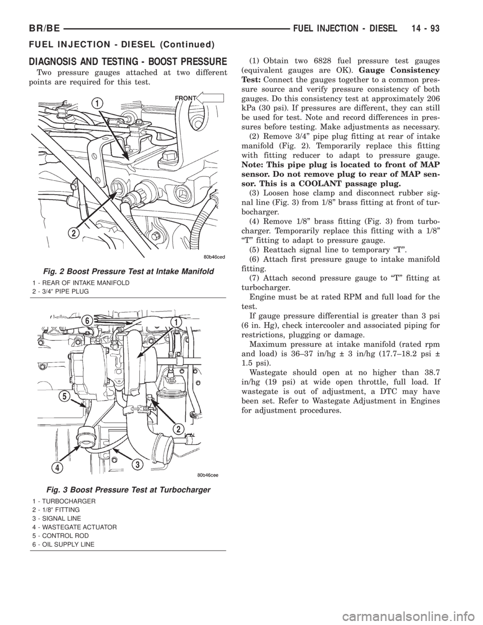
(2) Remove 3/4º pipe plug fitting at rear of intake
manifold (Fig. 2). Temporarily replace this fitting
with fitting reducer to adapt to pressure gauge.
Note: This pipe plug is located to front of MAP
sensor. Do not remove plug to rear of MAP sen-
sor. This is a COOLANT passage plug.
(3) Loosen hose clamp and disconnect rubber sig-
nal line (Fig. 3) from 1/8º brass fitting at front of tur-
bocharger.
(4) Remove 1/8º brass fitting (Fig. 3) from turbo-
charger. Temporarily replace this fitting with a 1/8º
ªTº fitting to adapt to pressure gauge.
(5) Reattach signal line to temporary ªTº.
(6) Attach first pressure gauge to intake manifold
fitting.
(7) Attach second pressure gauge to ªTº fitting at
turbocharger.
Engine must be at rated RPM and full load for the
test.
If gauge pressure differential is greater than 3 psi
(6 in. Hg), check intercooler and associated piping for
restrictions, plugging or damage.
Maximum pressure at intake manifold (rated rpm
and load) is 36±37 in/hg 3 in/hg (17.7±18.2 psi
1.5 psi).
Wastegate should open at no higher than 38.7
in/hg (19 psi) at wide open throttle, full load. If
wastegate is out of adjustment, a DTC may have
been set. Refer to Wastegate Adjustment in Engines
for adjustment procedures.
Fig. 2 Boost Pressure Test at Intake Manifold
1 - REAR OF INTAKE MANIFOLD
2 - 3/49PIPE PLUG
Fig. 3 Boost Pressure Test at Turbocharger
1 - TURBOCHARGER
2 - 1/89FITTING
3 - SIGNAL LINE
4 - WASTEGATE ACTUATOR
5 - CONTROL ROD
6 - OIL SUPPLY LINE
BR/BEFUEL INJECTION - DIESEL 14 - 93
FUEL INJECTION - DIESEL (Continued)
Page 1402 of 2255
(g) If any of these conditions occur, replace injec-
tor.
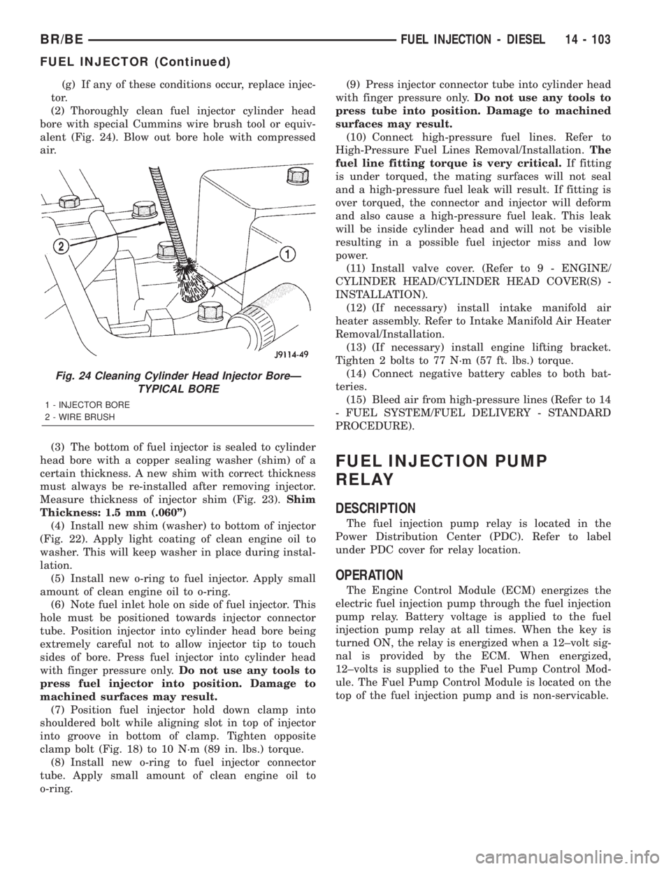
(2) Thoroughly clean fuel injector cylinder head
bore with special Cummins wire brush tool or equiv-
alent (Fig. 24). Blow out bore hole with compressed
air.
(3) The bottom of fuel injector is sealed to cylinder
head bore with a copper sealing washer (shim) of a
certain thickness. A new shim with correct thickness
must always be re-installed after removing injector.
Measure thickness of injector shim (Fig. 23).Shim
Thickness: 1.5 mm (.060º)
(4) Install new shim (washer) to bottom of injector
(Fig. 22). Apply light coating of clean engine oil to
washer. This will keep washer in place during instal-
lation.
(5) Install new o-ring to fuel injector. Apply small
amount of clean engine oil to o-ring.
(6) Note fuel inlet hole on side of fuel injector. This
hole must be positioned towards injector connector
tube. Position injector into cylinder head bore being
extremely careful not to allow injector tip to touch
sides of bore. Press fuel injector into cylinder head
with finger pressure only.Do not use any tools to
press fuel injector into position. Damage to
machined surfaces may result.
(7) Position fuel injector hold down clamp into
shouldered bolt while aligning slot in top of injector
into groove in bottom of clamp. Tighten opposite
clamp bolt (Fig. 18) to 10 N´m (89 in. lbs.) torque.
(8) Install new o-ring to fuel injector connector
tube. Apply small amount of clean engine oil to
o-ring.(9) Press injector connector tube into cylinder head
with finger pressure only.Do not use any tools to
press tube into position. Damage to machined
surfaces may result.
(10) Connect high-pressure fuel lines. Refer to
High-Pressure Fuel Lines Removal/Installation.The
fuel line fitting torque is very critical.If fitting
is under torqued, the mating surfaces will not seal
and a high-pressure fuel leak will result. If fitting is
over torqued, the connector and injector will deform
and also cause a high-pressure fuel leak. This leak
will be inside cylinder head and will not be visible
resulting in a possible fuel injector miss and low
power.
(11) Install valve cover. (Refer to 9 - ENGINE/
CYLINDER HEAD/CYLINDER HEAD COVER(S) -
INSTALLATION).
(12) (If necessary) install intake manifold air
heater assembly. Refer to Intake Manifold Air Heater
Removal/Installation.
(13) (If necessary) install engine lifting bracket.
Tighten 2 bolts to 77 N´m (57 ft. lbs.) torque.
(14) Connect negative battery cables to both bat-
teries.
(15) Bleed air from high-pressure lines (Refer to 14
- FUEL SYSTEM/FUEL DELIVERY - STANDARD
PROCEDURE).
FUEL INJECTION PUMP
RELAY
DESCRIPTION
The fuel injection pump relay is located in the
Power Distribution Center (PDC). Refer to label
under PDC cover for relay location.
OPERATION
The Engine Control Module (ECM) energizes the
electric fuel injection pump through the fuel injection
pump relay. Battery voltage is applied to the fuel
injection pump relay at all times. When the key is
turned ON, the relay is energized when a 12±volt sig-
nal is provided by the ECM. When energized,
12±volts is supplied to the Fuel Pump Control Mod-
ule. The Fuel Pump Control Module is located on the
top of the fuel injection pump and is non-servicable.
Fig. 24 Cleaning Cylinder Head Injector BoreÐ
TYPICAL BORE
1 - INJECTOR BORE
2 - WIRE BRUSH
BR/BEFUEL INJECTION - DIESEL 14 - 103
FUEL INJECTOR (Continued)
Page 1404 of 2255
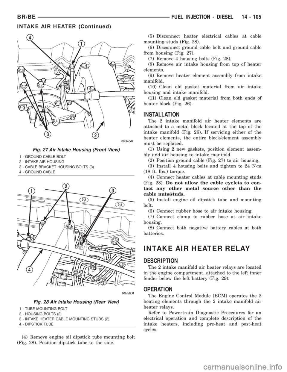
(4) Remove engine oil dipstick tube mounting bolt
(Fig. 28). Position dipstick tube to the side.(5) Disconnect heater electrical cables at cable
mounting studs (Fig. 28).
(6) Disconnect ground cable bolt and ground cable
from housing (Fig. 27).
(7) Remove 4 housing bolts (Fig. 28).
(8) Remove air intake housing from top of heater
elements.
(9) Remove heater element assembly from intake
manifold.
(10) Clean old gasket material from air intake
housing and intake manifold.
(11) Clean old gasket material from both ends of
heater block (Fig. 26).
INSTALLATION
The 2 intake manifold air heater elements are
attached to a metal block located at the top of the
intake manifold (Fig. 26). If servicing either of the
heater elements, the entire block/element assembly
must be replaced.
(1) Using 2 new gaskets, position element assem-
bly and air housing to intake manifold.
(2) Position ground cable (Fig. 27) to air housing.
(3) Install 4 housing bolts and tighten to 24 N´m
(18 ft. lbs.) torque.
(4) Connect heater cables at cable mounting studs
(Fig. 28).Do not allow the cable eyelets to con-
tact any other metal source other than the
cable nuts/studs.
(5) Install engine oil dipstick tube and mounting
bolt.
(6) Connect rubber hose to air intake housing.
(7) Connect clamp to rubber hose at air intake
housing.
(8) Connect both negative battery cables at both
batteries.
INTAKE AIR HEATER RELAY
DESCRIPTION
The 2 intake manifold air heater relays are located
in the engine compartment, attached to the left inner
fender below the left battery (Fig. 29).
OPERATION
The Engine Control Module (ECM) operates the 2
heating elements through the 2 intake manifold air
heater relays.
Refer to Powertrain Diagnostic Procedures for an
electrical operation and complete description of the
intake heaters, including pre-heat and post-heat
cycles.
Fig. 27 Air Intake Housing (Front View)
1 - GROUND CABLE BOLT
2 - INTAKE AIR HOUSING
3 - CABLE BRACKET HOUSING BOLTS (3)
4 - GROUND CABLE
Fig. 28 Air Intake Housing (Rear View)
1 - TUBE MOUNTING BOLT
2 - HOUSING BOLTS (2)
3 - INTAKE HEATER CABLE MOUNTING STUDS (2)
4 - DIPSTICK TUBE
BR/BEFUEL INJECTION - DIESEL 14 - 105
INTAKE AIR HEATER (Continued)
Page 1406 of 2255
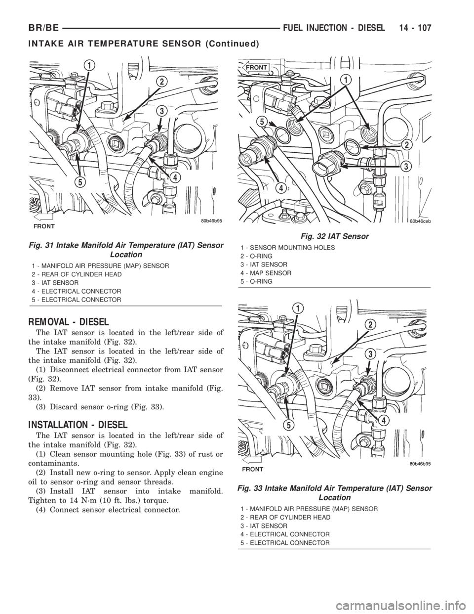
REMOVAL - DIESEL
The IAT sensor is located in the left/rear side of
the intake manifold (Fig. 32).
The IAT sensor is located in the left/rear side of
the intake manifold (Fig. 32).
(1) Disconnect electrical connector from IAT sensor
(Fig. 32).
(2) Remove IAT sensor from intake manifold (Fig.
33).
(3) Discard sensor o-ring (Fig. 33).
INSTALLATION - DIESEL
The IAT sensor is located in the left/rear side of
the intake manifold (Fig. 32).
(1) Clean sensor mounting hole (Fig. 33) of rust or
contaminants.
(2) Install new o-ring to sensor. Apply clean engine
oil to sensor o-ring and sensor threads.
(3) Install IAT sensor into intake manifold.
Tighten to 14 N´m (10 ft. lbs.) torque.
(4) Connect sensor electrical connector.
Fig. 31 Intake Manifold Air Temperature (IAT) Sensor
Location
1 - MANIFOLD AIR PRESSURE (MAP) SENSOR
2 - REAR OF CYLINDER HEAD
3 - IAT SENSOR
4 - ELECTRICAL CONNECTOR
5 - ELECTRICAL CONNECTOR
Fig. 32 IAT Sensor
1 - SENSOR MOUNTING HOLES
2 - O-RING
3 - IAT SENSOR
4 - MAP SENSOR
5 - O-RING
Fig. 33 Intake Manifold Air Temperature (IAT) Sensor
Location
1 - MANIFOLD AIR PRESSURE (MAP) SENSOR
2 - REAR OF CYLINDER HEAD
3 - IAT SENSOR
4 - ELECTRICAL CONNECTOR
5 - ELECTRICAL CONNECTOR
BR/BEFUEL INJECTION - DIESEL 14 - 107
INTAKE AIR TEMPERATURE SENSOR (Continued)
Page 1407 of 2255
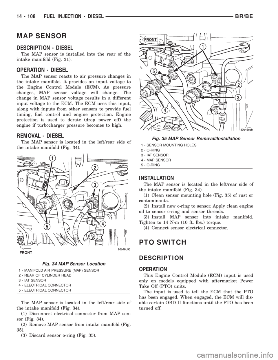
MAP SENSOR
DESCRIPTION - DIESEL
The MAP sensor is installed into the rear of the
intake manifold (Fig. 31).
OPERATION - DIESEL
The MAP sensor reacts to air pressure changes in
the intake manifold. It provides an input voltage to
the Engine Control Module (ECM). As pressure
changes, MAP sensor voltage will change. The
change in MAP sensor voltage results in a different
input voltage to the ECM. The ECM uses this input,
along with inputs from other sensors to provide fuel
timing, fuel control and engine protection. Engine
protection is used to derate (drop power off) the
engine if turbocharger pressure becomes to high.
REMOVAL - DIESEL
The MAP sensor is located in the left/rear side of
the intake manifold (Fig. 34).
The MAP sensor is located in the left/rear side of
the intake manifold (Fig. 34).
(1) Disconnect electrical connector from MAP sen-
sor (Fig. 34).
(2) Remove MAP sensor from intake manifold (Fig.
35).
(3) Discard sensor o-ring (Fig. 35).
INSTALLATION
The MAP sensor is located in the left/rear side of
the intake manifold (Fig. 34).
(1) Clean sensor mounting hole (Fig. 35) of rust or
contaminants.
(2) Install new o-ring to sensor. Apply clean engine
oil to sensor o-ring and sensor threads.
(3) Install MAP sensor into intake manifold.
Tighten to 14 N´m (10 ft. lbs.) torque.
(4) Connect sensor electrical connector.
PTO SWITCH
DESCRIPTION
OPERATION
This Engine Control Module (ECM) input is used
only on models equipped with aftermarket Power
Take Off (PTO) units.
The input is used to tell the ECM that the PTO
has been engaged. When engaged, the ECM will dis-
able certain OBD II functions until the PTO has been
turned off.
Fig. 34 MAP Sensor Location
1 - MANIFOLD AIR PRESSURE (MAP) SENSOR
2 - REAR OF CYLINDER HEAD
3 - IAT SENSOR
4 - ELECTRICAL CONNECTOR
5 - ELECTRICAL CONNECTOR
Fig. 35 MAP Sensor Removal/Installation
1 - SENSOR MOUNTING HOLES
2 - O-RING
3 - IAT SENSOR
4 - MAP SENSOR
5 - O-RING
14 - 108 FUEL INJECTION - DIESELBR/BE
Page 1410 of 2255
STEERING
TABLE OF CONTENTS
page page
STEERING
DESCRIPTION..........................1
OPERATION............................1
DIAGNOSIS AND TESTING
DIAGNOSIS AND TESTING - POWER
STEERING SYSTEM....................2
DIAGNOSIS AND TESTING - POWER
STEERING FLOW AND PRESSURE........4COLUMN...............................6
GEAR.................................16
PUMP.................................33
LINKAGE - 2WD.........................40
LINKAGE - 4WD.........................42
STEERING
DESCRIPTION
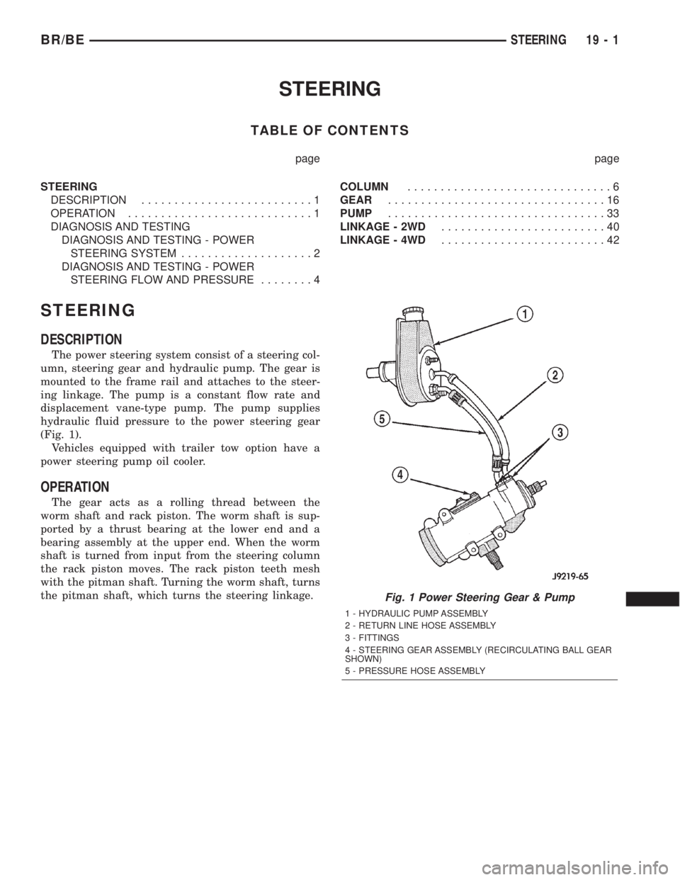
The power steering system consist of a steering col-
umn, steering gear and hydraulic pump. The gear is
mounted to the frame rail and attaches to the steer-
ing linkage. The pump is a constant flow rate and
displacement vane-type pump. The pump supplies
hydraulic fluid pressure to the power steering gear
(Fig. 1).
Vehicles equipped with trailer tow option have a
power steering pump oil cooler.
OPERATION
The gear acts as a rolling thread between the
worm shaft and rack piston. The worm shaft is sup-
ported by a thrust bearing at the lower end and a
bearing assembly at the upper end. When the worm
shaft is turned from input from the steering column
the rack piston moves. The rack piston teeth mesh
with the pitman shaft. Turning the worm shaft, turns
the pitman shaft, which turns the steering linkage.
Fig. 1 Power Steering Gear & Pump
1 - HYDRAULIC PUMP ASSEMBLY
2 - RETURN LINE HOSE ASSEMBLY
3 - FITTINGS
4 - STEERING GEAR ASSEMBLY (RECIRCULATING BALL GEAR
SHOWN)
5 - PRESSURE HOSE ASSEMBLY
BR/BESTEERING 19 - 1
Page 1431 of 2255
SPECIAL TOOLS
POWER STEERING GEAR
PITMAN BEARING
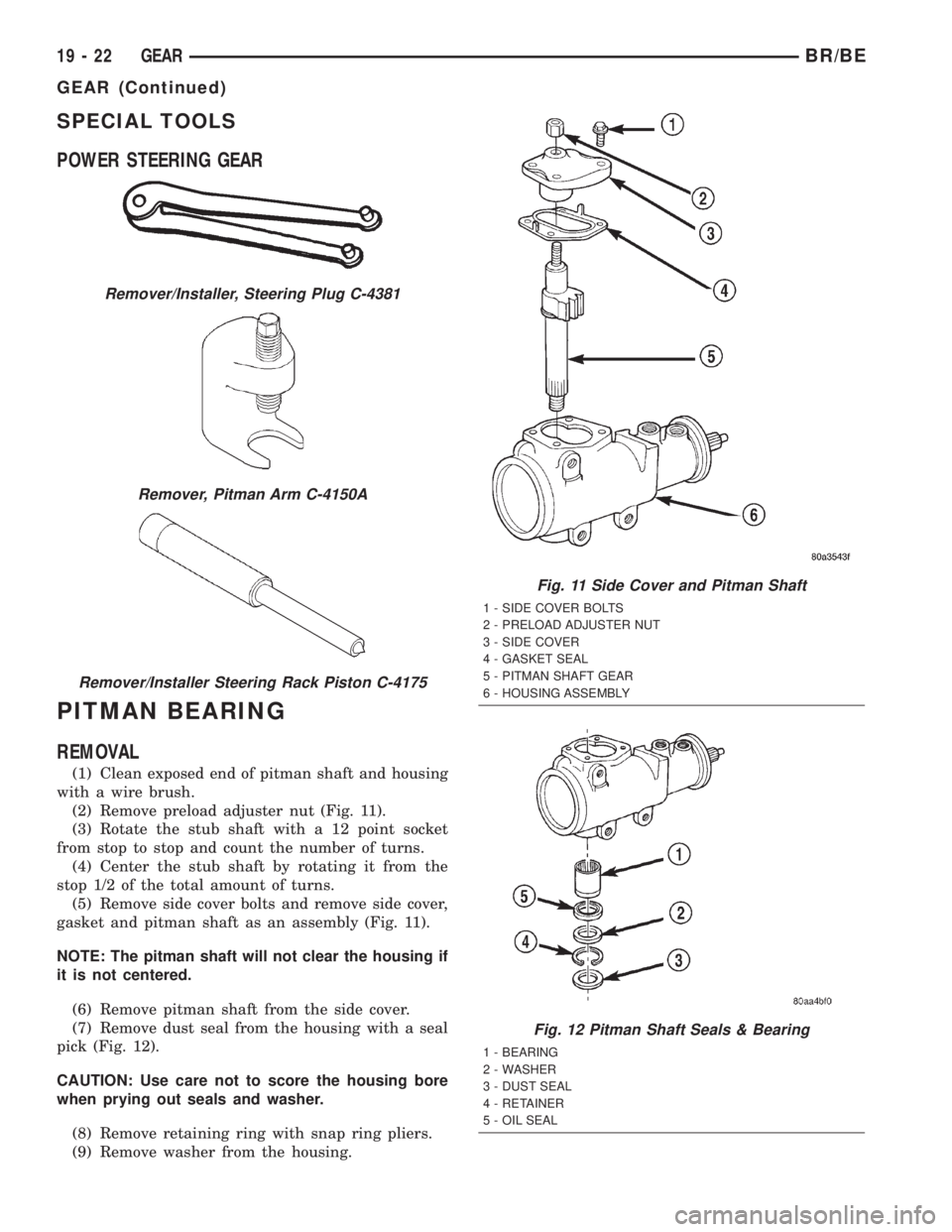
REMOVAL
(1) Clean exposed end of pitman shaft and housing
with a wire brush.
(2) Remove preload adjuster nut (Fig. 11).
(3) Rotate the stub shaft with a 12 point socket
from stop to stop and count the number of turns.
(4) Center the stub shaft by rotating it from the
stop 1/2 of the total amount of turns.
(5) Remove side cover bolts and remove side cover,
gasket and pitman shaft as an assembly (Fig. 11).
NOTE: The pitman shaft will not clear the housing if
it is not centered.
(6) Remove pitman shaft from the side cover.
(7) Remove dust seal from the housing with a seal
pick (Fig. 12).
CAUTION: Use care not to score the housing bore
when prying out seals and washer.
(8) Remove retaining ring with snap ring pliers.
(9) Remove washer from the housing.
Remover/Installer, Steering Plug C-4381
Remover, Pitman Arm C-4150A
Remover/Installer Steering Rack Piston C-4175
Fig. 11 Side Cover and Pitman Shaft
1 - SIDE COVER BOLTS
2 - PRELOAD ADJUSTER NUT
3 - SIDE COVER
4 - GASKET SEAL
5 - PITMAN SHAFT GEAR
6 - HOUSING ASSEMBLY
Fig. 12 Pitman Shaft Seals & Bearing
1 - BEARING
2 - WASHER
3 - DUST SEAL
4 - RETAINER
5 - OIL SEAL
19 - 22 GEARBR/BE
GEAR (Continued)