2002 DODGE RAM oil
[x] Cancel search: oilPage 1258 of 2255
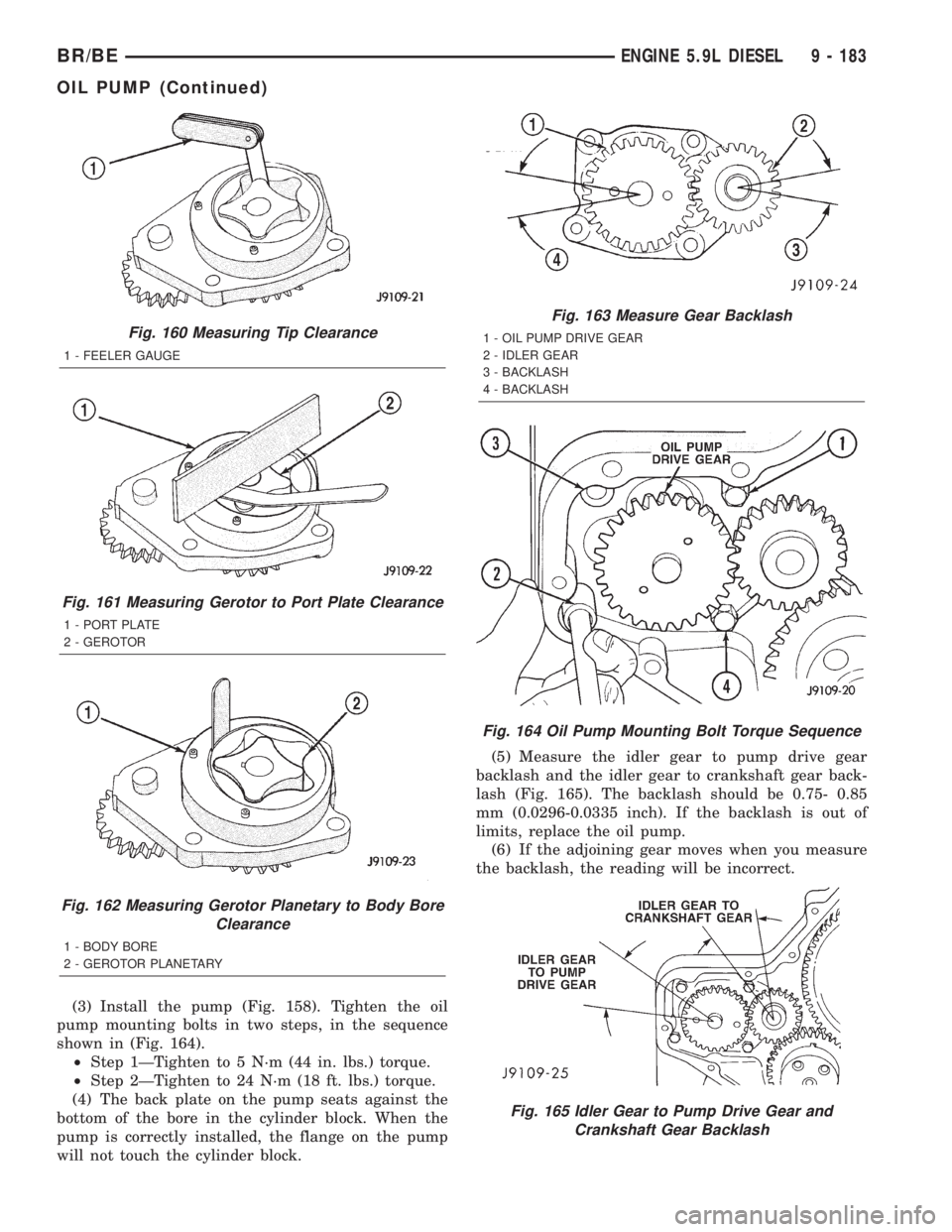
(3) Install the pump (Fig. 158). Tighten the oil
pump mounting bolts in two steps, in the sequence
shown in (Fig. 164).
²Step 1ÐTighten to 5 N´m (44 in. lbs.) torque.
²Step 2ÐTighten to 24 N´m (18 ft. lbs.) torque.
(4) The back plate on the pump seats against the
bottom of the bore in the cylinder block. When the
pump is correctly installed, the flange on the pump
will not touch the cylinder block.(5) Measure the idler gear to pump drive gear
backlash and the idler gear to crankshaft gear back-
lash (Fig. 165). The backlash should be 0.75- 0.85
mm (0.0296-0.0335 inch). If the backlash is out of
limits, replace the oil pump.
(6) If the adjoining gear moves when you measure
the backlash, the reading will be incorrect.
Fig. 160 Measuring Tip Clearance
1 - FEELER GAUGE
Fig. 161 Measuring Gerotor to Port Plate Clearance
1 - PORT PLATE
2 - GEROTOR
Fig. 162 Measuring Gerotor Planetary to Body Bore
Clearance
1 - BODY BORE
2 - GEROTOR PLANETARY
Fig. 163 Measure Gear Backlash
1 - OIL PUMP DRIVE GEAR
2 - IDLER GEAR
3 - BACKLASH
4 - BACKLASH
Fig. 164 Oil Pump Mounting Bolt Torque Sequence
Fig. 165 Idler Gear to Pump Drive Gear and
Crankshaft Gear Backlash
BR/BEENGINE 5.9L DIESEL 9 - 183
OIL PUMP (Continued)
Page 1259 of 2255
(7) Apply a bead of MopartSilicone Rubber Adhe-
sive Sealant or equivalent to the gear housing cover
sealing surface.
(8) Install the gear housing cover (Refer to 9 -
ENGINE/VALVE TIMING/GEAR HOUSING COVER
- INSTALLATION).
(9) Install the vibration damper (Refer to 9 -
ENGINE/ENGINE BLOCK/VIBRATION DAMPER -
INSTALLATION).
(10) Install the fan support/hub assembly and
torque bolts to 24 N´m (18 ft. lbs.).
(11) Install the accessory drive belt (Refer to 7 -
COOLING/ACCESSORY DRIVE/DRIVE BELTS -
INSTALLATION).
(12) Install the cooling fan (Refer to 7 - COOLING/
ENGINE/RADIATOR FAN - INSTALLATION).
(13) Connect battery negative cables.
(14) Start engine and check for oil leaks.
INTAKE MANIFOLD
REMOVAL
(1) Disconnect the battery negative cables.
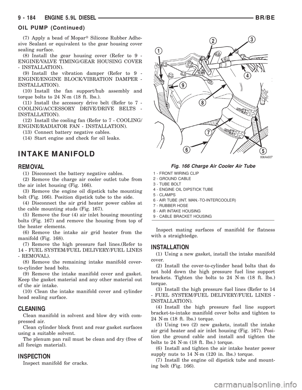
(2) Remove the charge air cooler outlet tube from
the air inlet housing (Fig. 166).
(3) Remove the engine oil dipstick tube mounting
bolt (Fig. 166). Position dipstick tube to the side.
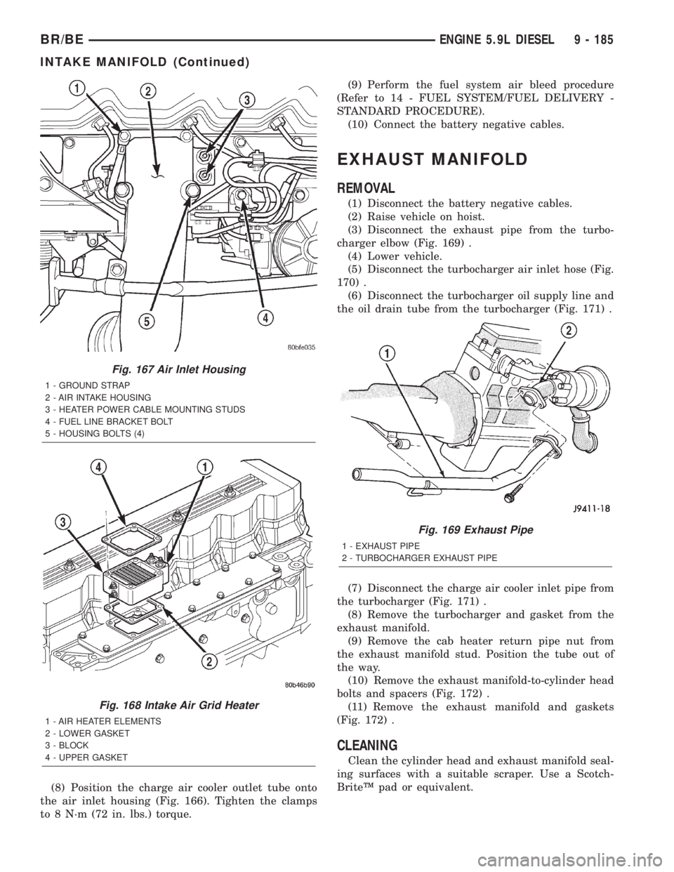
(4) Disconnect the air grid heater power cables at
the cable mounting studs (Fig. 167).
(5) Remove the four (4) air inlet housing mounting
bolts (Fig. 167) and remove the housing from top of
the heater elements.
(6) Remove the intake air grid heater from the
manifold (Fig. 168).
(7) Remove the high pressure fuel lines.(Refer to
14 - FUEL SYSTEM/FUEL DELIVERY/FUEL LINES
- REMOVAL).
(8) Remove the remaining intake manifold cover-
to-cylinder head bolts.
(9) Remove the intake manifold cover and gasket.
Keep the gasket material and any other material out
of the air intake.
(10) Clean the intake manifold cover and cylinder
head sealing surface.
CLEANING
Clean manifold in solvent and blow dry with com-
pressed air.
Clean cylinder block front and rear gasket surfaces
using a suitable solvent.
The plenum pan rail must be clean and dry (free of
all foreign material).
INSPECTION
Inspect manifold for cracks.Inspect mating surfaces of manifold for flatness
with a straightedge.
INSTALLATION
(1) Using a new gasket, install the intake manifold
cover.
(2) Install the cover-to-cylinder head bolts that do
not hold down the high pressure fuel line support
brackets. Tighten the bolts to 24 N´m (18 ft. lbs.)
torque.
(3) Install the high pressure fuel lines (Refer to 14
- FUEL SYSTEM/FUEL DELIVERY/FUEL LINES -
INSTALLATION).
(4) Install the high pressure fuel line support
bracket-to-intake manifold cover bolts and tighten to
24 N´m (18 ft. lbs.) torque.
(5) Using two (2) new gaskets, install the intake
air grid heater and air inlet housing (Fig. 167). Posi-
tion the ground cable and install and tighten the
bolts to 24 N´m (18 ft. lbs.) torque.
(6) Install and tighten the air intake heater power
supply nuts to 14 N´m (120 in. lbs.) torque.
(7) Install the engine oil dipstick tube and mount-
ing bolt (Fig. 166).
Fig. 166 Charge Air Cooler Air Tube
1 - FRONT WIRING CLIP
2 - GROUND CABLE
3 - TUBE BOLT
4 - ENGINE OIL DIPSTICK TUBE
5 - CLAMPS
6 - AIR TUBE (INT. MAN.-TO-INTERCOOLER)
7 - RUBBER HOSE
8 - AIR INTAKE HOUSING
9 - CABLE BRACKET HOUSING
9 - 184 ENGINE 5.9L DIESELBR/BE
OIL PUMP (Continued)
Page 1260 of 2255
(8) Position the charge air cooler outlet tube onto
the air inlet housing (Fig. 166). Tighten the clamps
to 8 N´m (72 in. lbs.) torque.(9) Perform the fuel system air bleed procedure
(Refer to 14 - FUEL SYSTEM/FUEL DELIVERY -
STANDARD PROCEDURE).
(10) Connect the battery negative cables.
EXHAUST MANIFOLD
REMOVAL
(1) Disconnect the battery negative cables.
(2) Raise vehicle on hoist.
(3) Disconnect the exhaust pipe from the turbo-
charger elbow (Fig. 169) .
(4) Lower vehicle.
(5) Disconnect the turbocharger air inlet hose (Fig.
170) .
(6) Disconnect the turbocharger oil supply line and
the oil drain tube from the turbocharger (Fig. 171) .
(7) Disconnect the charge air cooler inlet pipe from
the turbocharger (Fig. 171) .
(8) Remove the turbocharger and gasket from the
exhaust manifold.
(9) Remove the cab heater return pipe nut from
the exhaust manifold stud. Position the tube out of
the way.
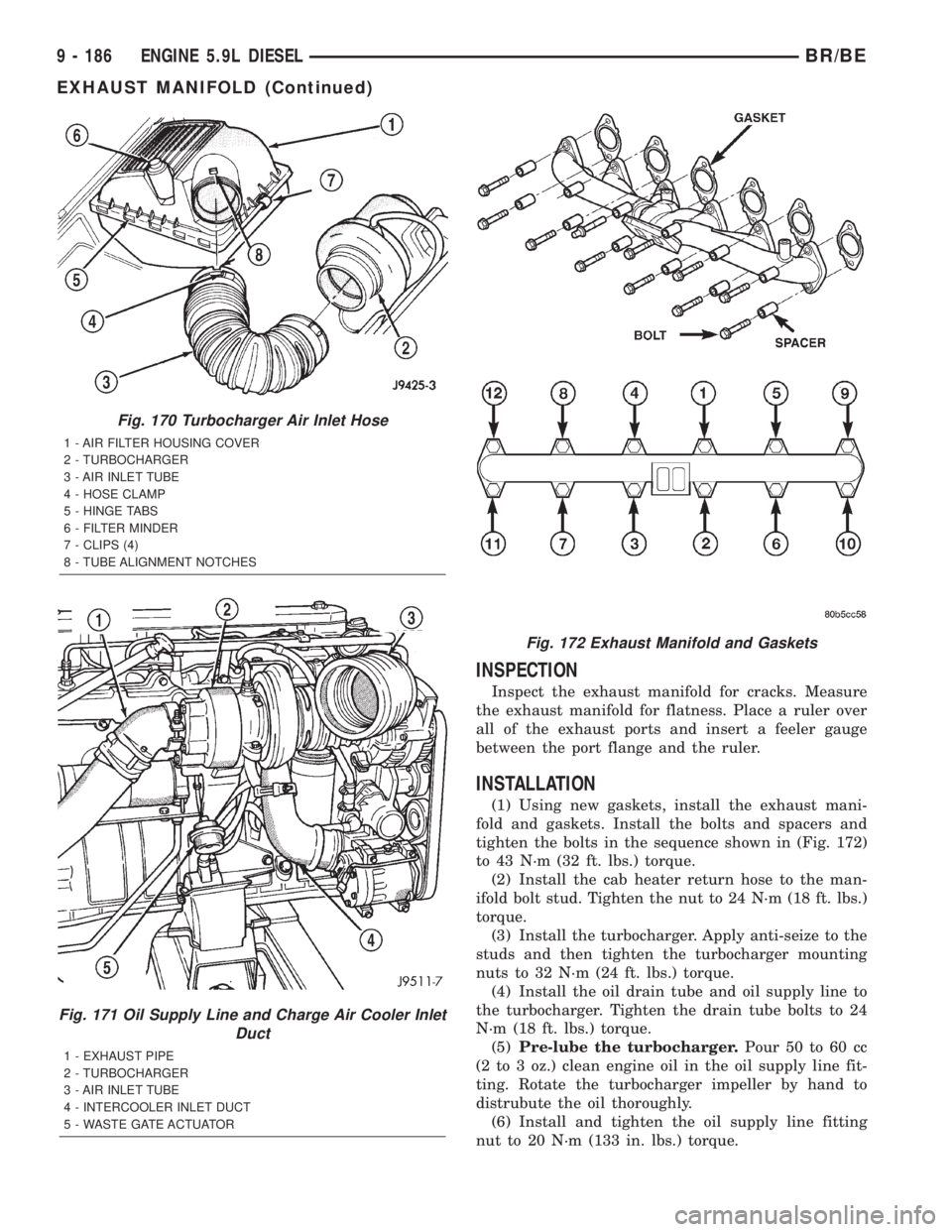
(10) Remove the exhaust manifold-to-cylinder head
bolts and spacers (Fig. 172) .
(11) Remove the exhaust manifold and gaskets
(Fig. 172) .
CLEANING
Clean the cylinder head and exhaust manifold seal-
ing surfaces with a suitable scraper. Use a Scotch-
BriteŸ pad or equivalent.
Fig. 167 Air Inlet Housing
1 - GROUND STRAP
2 - AIR INTAKE HOUSING
3 - HEATER POWER CABLE MOUNTING STUDS
4 - FUEL LINE BRACKET BOLT
5 - HOUSING BOLTS (4)
Fig. 168 Intake Air Grid Heater
1 - AIR HEATER ELEMENTS
2 - LOWER GASKET
3 - BLOCK
4 - UPPER GASKET
Fig. 169 Exhaust Pipe
1 - EXHAUST PIPE
2 - TURBOCHARGER EXHAUST PIPE
BR/BEENGINE 5.9L DIESEL 9 - 185
INTAKE MANIFOLD (Continued)
Page 1261 of 2255
INSPECTION
Inspect the exhaust manifold for cracks. Measure
the exhaust manifold for flatness. Place a ruler over
all of the exhaust ports and insert a feeler gauge
between the port flange and the ruler.
INSTALLATION
(1) Using new gaskets, install the exhaust mani-
fold and gaskets. Install the bolts and spacers and
tighten the bolts in the sequence shown in (Fig. 172)
to 43 N´m (32 ft. lbs.) torque.
(2) Install the cab heater return hose to the man-
ifold bolt stud. Tighten the nut to 24 N´m (18 ft. lbs.)
torque.
(3) Install the turbocharger. Apply anti-seize to the
studs and then tighten the turbocharger mounting
nuts to 32 N´m (24 ft. lbs.) torque.
(4) Install the oil drain tube and oil supply line to
the turbocharger. Tighten the drain tube bolts to 24
N´m (18 ft. lbs.) torque.
(5)Pre-lube the turbocharger.Pour 50 to 60 cc
(2 to 3 oz.) clean engine oil in the oil supply line fit-
ting. Rotate the turbocharger impeller by hand to
distrubute the oil thoroughly.
(6) Install and tighten the oil supply line fitting
nut to 20 N´m (133 in. lbs.) torque.
Fig. 170 Turbocharger Air Inlet Hose
1 - AIR FILTER HOUSING COVER
2 - TURBOCHARGER
3 - AIR INLET TUBE
4 - HOSE CLAMP
5 - HINGE TABS
6 - FILTER MINDER
7 - CLIPS (4)
8 - TUBE ALIGNMENT NOTCHES
Fig. 171 Oil Supply Line and Charge Air Cooler Inlet
Duct
1 - EXHAUST PIPE
2 - TURBOCHARGER
3 - AIR INLET TUBE
4 - INTERCOOLER INLET DUCT
5 - WASTE GATE ACTUATOR
Fig. 172 Exhaust Manifold and Gaskets
9 - 186 ENGINE 5.9L DIESELBR/BE
EXHAUST MANIFOLD (Continued)
Page 1263 of 2255
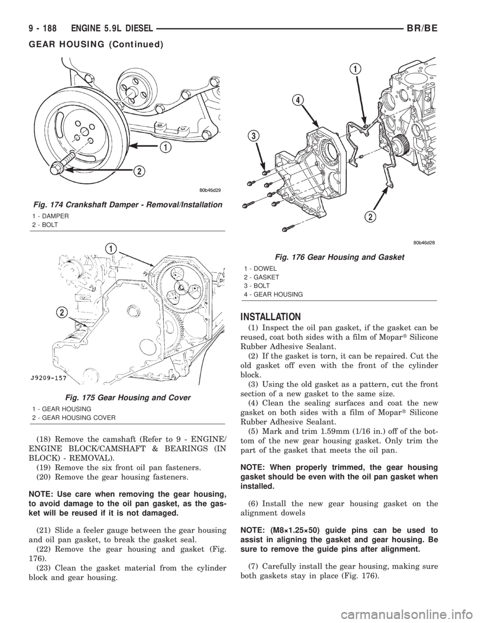
(18) Remove the camshaft (Refer to 9 - ENGINE/
ENGINE BLOCK/CAMSHAFT & BEARINGS (IN
BLOCK) - REMOVAL).
(19) Remove the six front oil pan fasteners.
(20) Remove the gear housing fasteners.
NOTE: Use care when removing the gear housing,
to avoid damage to the oil pan gasket, as the gas-
ket will be reused if it is not damaged.
(21) Slide a feeler gauge between the gear housing
and oil pan gasket, to break the gasket seal.
(22) Remove the gear housing and gasket (Fig.
176).
(23) Clean the gasket material from the cylinder
block and gear housing.
INSTALLATION
(1) Inspect the oil pan gasket, if the gasket can be
reused, coat both sides with a film of MopartSilicone
Rubber Adhesive Sealant.
(2) If the gasket is torn, it can be repaired. Cut the
old gasket off even with the front of the cylinder
block.
(3) Using the old gasket as a pattern, cut the front
section of a new gasket to the same size.
(4) Clean the sealing surfaces and coat the new
gasket on both sides with a film of MopartSilicone
Rubber Adhesive Sealant.
(5) Mark and trim 1.59mm (1/16 in.) off of the bot-
tom of the new gear housing gasket. Only trim the
part of the gasket that meets the oil pan.
NOTE: When properly trimmed, the gear housing
gasket should be even with the oil pan gasket when
installed.
(6) Install the new gear housing gasket on the
alignment dowels
NOTE: (M8ý1.25ý50) guide pins can be used to
assist in aligning the gasket and gear housing. Be
sure to remove the guide pins after alignment.
(7) Carefully install the gear housing, making sure
both gaskets stay in place (Fig. 176).
Fig. 174 Crankshaft Damper - Removal/Installation
1 - DAMPER
2 - BOLT
Fig. 175 Gear Housing and Cover
1 - GEAR HOUSING
2 - GEAR HOUSING COVER
Fig. 176 Gear Housing and Gasket
1 - DOWEL
2 - GASKET
3 - BOLT
4 - GEAR HOUSING
9 - 188 ENGINE 5.9L DIESELBR/BE
GEAR HOUSING (Continued)
Page 1264 of 2255
(8) Install and tighten the gear housing bolts to 24
N´m (18 ft. lbs.) torque.
(9) Install and tighten the oil pan bolts to 24 N´m
(18 ft. lbs.) torque.
(10) Install the camshaft (Refer to 9 - ENGINE/
ENGINE BLOCK/CAMSHAFT & BEARINGS (IN
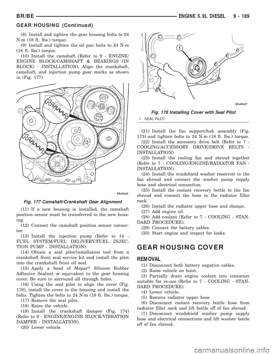
BLOCK) - INSTALLATION). Align the crankshaft,
camshaft, and injection pump gear marks as shown
in (Fig. 177).
(11) If a new housing is installed, the camshaft
position sensor must be transferred to the new hous-
ing.
(12) Connect the camshaft position sensor connec-
tor.
(13) Install the injection pump (Refer to 14 -
FUEL SYSTEM/FUEL DELIVERY/FUEL INJEC-
TION PUMP - INSTALLATION).
(14) Obtain a seal pilot/installation tool from a
crankshaft front seal service kit and install the pilot
into the crankshaft front oil seal.
(15) Apply a bead of MopartSilicone Rubber
Adhesive Sealant or equivalent to the gear housing
cover. Be sure to surround all through holes.
(16) Using the seal pilot to align the cover (Fig.
178), install the cover to the housing and install the
bolts. Tighten the bolts to 24 N´m (18 ft. lbs.) torque.
(17) Remove the seal pilot.
(18) Raise the vehicle.
(19) Install the crankshaft damper (Fig. 174)
(Refer to 9 - ENGINE/ENGINE BLOCK/VIBRATION
DAMPER - INSTALLATION).
(20) Lower vehicle.(21) Install the fan support/hub assembly (Fig.
173) and tighten bolts to 24 N´m (18 ft. lbs.) torque.
(22) Install the accessory drive belt (Refer to 7 -
COOLING/ACCESSORY DRIVE/DRIVE BELTS -
INSTALLATION).
(23) Install the cooling fan and shroud together
(Refer to 7 - COOLING/ENGINE/RADIATOR FAN -
INSTALLATION).
(24) Install the windshield washer reservoir to the
fan shroud and connect the washer pump supply
hose and electrical connection.
(25) Install the coolant recovery bottle to the fan
shroud and connect the hose to the radiator filler
neck.
(26) Install the radiator upper hose and clamps.
(27) Add engine oil.
(28) Add coolant (Refer to 7 - COOLING - STAN-
DARD PROCEDURE).
(29) Connect the battery cables.
(30) Start engine and inspect for leaks.
GEAR HOUSING COVER
REMOVAL
(1) Disconnect both battery negative cables.
(2) Raise vehicle on hoist.
(3) Partially drain engine coolant into container
suitable for re-use (Refer to 7 - COOLING - STAN-
DARD PROCEDURE).
(4) Lower vehicle.
(5) Remove radiator upper hose.
(6) Disconnect coolant recovery bottle hose from
radiator filler neck and lift bottle off of fan shroud.
(7) Disconnect windshield washer pump supply
hose and electrical connections and lift washer bottle
off of fan shroud.
Fig. 177 Camshaft/Crankshaft Gear Alignment
Fig. 178 Installing Cover with Seal Pilot
1 - SEAL PILOT
BR/BEENGINE 5.9L DIESEL 9 - 189
GEAR HOUSING (Continued)
Page 1272 of 2255
SPECIFICATIONS
TORQUE
DESCRIPTION N´m Ft. In.
Lbs. Lbs.
Adjusting StrapÐBolt 23 Ð 200
Air Heater Power SupplyÐ
Nuts14 Ð 124
Air Inlet HousingÐBolts 24 18 Ð
Cab Heater Supply/Return
LineÐNuts24 18 Ð
Exhaust ClampÐNuts 48 35 Ð
Exhaust Manifold to Cylinder
HeadÐBolts
(Diesel Engine) 43 32 Ð
Exhaust Manifold to Cylinder
HeadÐBolts
(5.9L) 31 23 Ð
Exhaust Manifold to Cylinder
HeadÐBolts
(8.0L) 22 Ð 195
Exhaust Pipe to ManifoldÐ
Bolts31 23 Ð
Generator MountingÐBolts 41 30 Ð
Charge Air Cooler
MountingÐBolts2Ð17
Charge Air Cooler DuctÐ
Nuts8Ð72
Heat ShieldÐNuts and Bolts 11 Ð 100
Turbocharger MountingÐ
Nuts32 24 Ð
Turbocharger Oil Drain
TubeÐBolts24 18 Ð
Turbocharger Oil Supply
LineÐFitting15 Ð 133
Turbocharger V-Band
ClampÐNut9Ð75
CATALYTIC CONVERTER -
3.9L/5.2L/5.9L
DESCRIPTION
The stainless steel catalytic converter is located
under the vehicle, integral to the exhaust pipe(s).
OPERATION
The catalytic converter captures and burns any
unburned fuel mixture exiting the combustion cham-
bers during the exhaust stroke of the engine. This
process aids in reducing emissions output.
REMOVAL
(1) Raise and support vehicle.
(2) Saturate the bolts and nuts with heat valve
lubricant. Allow 5 minutes for penetration.
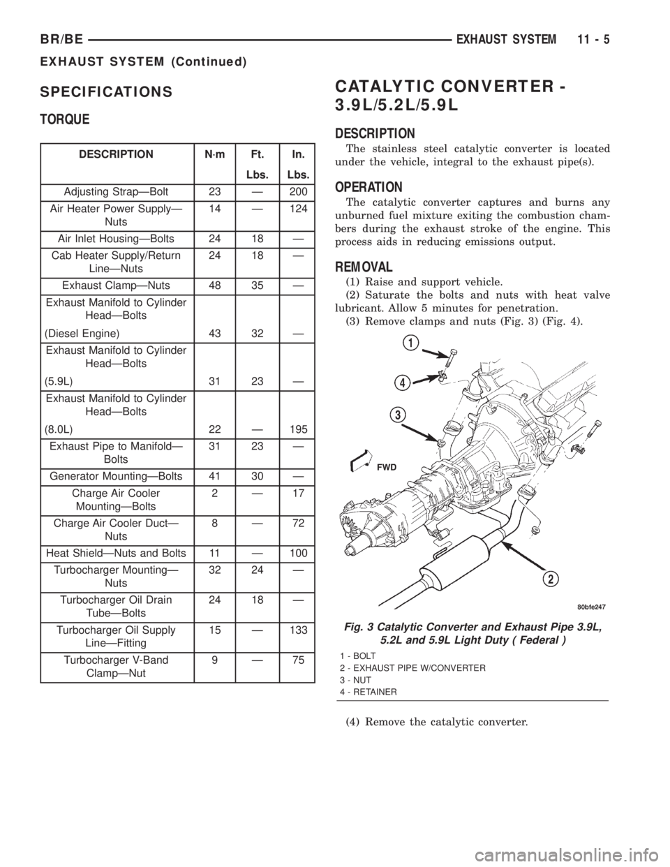
(3) Remove clamps and nuts (Fig. 3) (Fig. 4).
(4) Remove the catalytic converter.
Fig. 3 Catalytic Converter and Exhaust Pipe 3.9L,
5.2L and 5.9L Light Duty ( Federal )
1 - BOLT
2 - EXHAUST PIPE W/CONVERTER
3 - NUT
4 - RETAINER
BR/BEEXHAUST SYSTEM 11 - 5
EXHAUST SYSTEM (Continued)
Page 1277 of 2255

HEAT SHIELDS
DESCRIPTION
There are two types of heat shields used. One is
stamped steel the other is molded foil sheets. The
shields attach to the vehicle around the exhaust sys-
tem to prevent heat from the exhaust system from
entering the passenger area and other areas where
the heat can cause damage to other components.
REMOVAL
(1) Raise and support the vehicle.
(2) Remove the nuts or bolts holding the exhaust
heat shield to the floor pan, crossmember or bracket.
(3) Slide the shield out around the exhaust system.
INSTALLATION
(1) Position the exhaust heat shield to the floor
pan, crossmember or bracket and install the nuts or
bolts.
(2) Tighten the nuts and bolts 11 N´m (100 in.
lbs.).
(3) Lower the vehicle.
MUFFLER - 3.9L/5.2L/5.9L/8.0L
REMOVAL
(1) Raise and support the vehicle.
(2) Saturate the clamp nuts with heat valve lubri-
cant. Allow 5 minutes for penetration.
(3) Disconnect the muffler hanger (Fig. 12) (Fig.
13).
(4) Remove clamps and nuts (Fig. 12) (Fig. 13).
(5) Remove the muffler.
INSTALLATION
(1) Assemble muffler and clamps loosely to permit
proper alignment of all parts.
(2) Connect the muffler hanger.
(3) Tighten the clamp nuts to 48 N´m (35 ft. lbs.)
torque.
(4) Lower the vehicle.
(5) Start the engine and inspect for exhaust leaks
and exhaust system contact with the body panels. A
minimum of 25.4 mm (1.0 in.) is required between
exhaust system components and body/frame parts.
Adjust the alignment, if needed.
Fig. 12 Muffler for 3.9L, 5.2L and 5.9L-Light Duty Engines
1 - TAILPIPE
2 - CLAMP3 - MUFFLER LIGHT DUTY
11 - 10 EXHAUST SYSTEMBR/BE