2002 DODGE RAM torque
[x] Cancel search: torquePage 1399 of 2255
(2) Note RPM drop for each cylinder. As an alter-
native, loosen high-pressure fuel line fitting at fuel
injector connector tube (Fig. 15). Listen for a change
in engine speed. After testing, tighten line fitting to
40 N´m (30 ft. lbs.) torque. If engine speed drops,
injector was operating normally. If engine speed
remains same, injector may be malfunctioning. Test
all injectors in same manner one at a time.(3) Once injector has been found to be malfunc-
tioning, remove it from engine and test it. Refer to
Fuel Injector Removal/Installation.
WARNING: FUEL INJECTOR TESTERS CAN
DEVELOP EXTREMELY HIGH PRESSURES. FUEL
UNDER THIS AMOUNT OF PRESSURE CAN PENE-
TRATE SKIN AND CAUSE PERSONAL INJURY.
WEAR SAFETY GOGGLES AND ADEQUATE PRO-
TECTIVE CLOTHING. AVOID CONTACT WITH FUEL
SPRAY WHEN OPERATING INJECTOR TESTOR.
(4)
After injector has been removed, obtain bench-
mount fuel injector tester OTCt(SPXt) part number
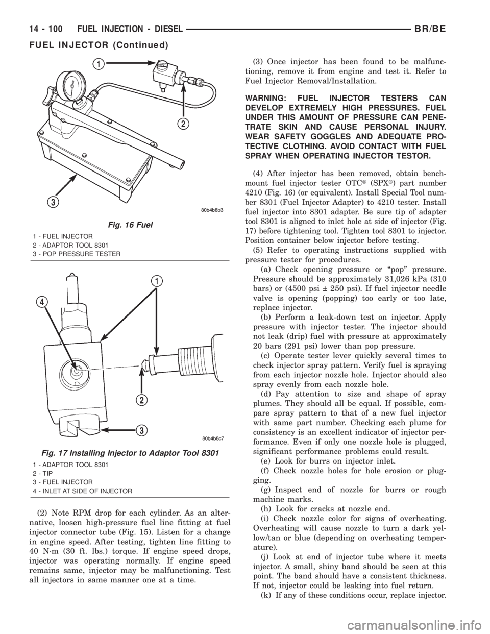
4210 (Fig. 16) (or equivalent). Install Special Tool num-
ber 8301 (Fuel Injector Adapter) to 4210 tester. Install
fuel injector into 8301 adapter. Be sure tip of adapter
tool 8301 is aligned to inlet hole at side of injector (Fig.
17) before tightening tool. Tighten tool 8301 to injector.
Position container below injector before testing.
(5) Refer to operating instructions supplied with
pressure tester for procedures.
(a) Check opening pressure or ªpopº pressure.
Pressure should be approximately 31,026 kPa (310
bars) or (4500 psi 250 psi). If fuel injector needle
valve is opening (popping) too early or too late,
replace injector.
(b) Perform a leak-down test on injector. Apply
pressure with injector tester. The injector should
not leak (drip) fuel with pressure at approximately
20 bars (291 psi) lower than pop pressure.
(c) Operate tester lever quickly several times to
check injector spray pattern. Verify fuel is spraying
from each injector nozzle hole. Injector should also
spray evenly from each nozzle hole.
(d) Pay attention to size and shape of spray
plumes. They should all be equal. If possible, com-
pare spray pattern to that of a new fuel injector
with same part number. Checking each plume for
consistency is an excellent indicator of injector per-
formance. Even if only one nozzle hole is plugged,
significant performance problems could result.
(e) Look for burrs on injector inlet.
(f) Check nozzle holes for hole erosion or plug-
ging.
(g) Inspect end of nozzle for burrs or rough
machine marks.
(h) Look for cracks at nozzle end.
(i) Check nozzle color for signs of overheating.
Overheating will cause nozzle to turn a dark yel-
low/tan or blue (depending on overheating temper-
ature).
(j)
Look at end of injector tube where it meets
injector. A small, shiny band should be seen at this
point. The band should have a consistent thickness.
If not, injector could be leaking into fuel return.
(k)If any of these conditions occur, replace injector.
Fig. 16 Fuel
1 - FUEL INJECTOR
2 - ADAPTOR TOOL 8301
3 - POP PRESSURE TESTER
Fig. 17 Installing Injector to Adaptor Tool 8301
1 - ADAPTOR TOOL 8301
2 - TIP
3 - FUEL INJECTOR
4 - INLET AT SIDE OF INJECTOR
14 - 100 FUEL INJECTION - DIESELBR/BE
FUEL INJECTOR (Continued)
Page 1402 of 2255
(g) If any of these conditions occur, replace injec-
tor.
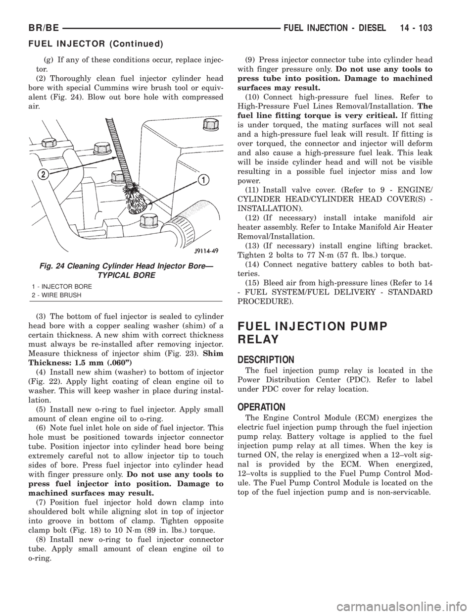
(2) Thoroughly clean fuel injector cylinder head
bore with special Cummins wire brush tool or equiv-
alent (Fig. 24). Blow out bore hole with compressed
air.
(3) The bottom of fuel injector is sealed to cylinder
head bore with a copper sealing washer (shim) of a
certain thickness. A new shim with correct thickness
must always be re-installed after removing injector.
Measure thickness of injector shim (Fig. 23).Shim
Thickness: 1.5 mm (.060º)
(4) Install new shim (washer) to bottom of injector
(Fig. 22). Apply light coating of clean engine oil to
washer. This will keep washer in place during instal-
lation.
(5) Install new o-ring to fuel injector. Apply small
amount of clean engine oil to o-ring.
(6) Note fuel inlet hole on side of fuel injector. This
hole must be positioned towards injector connector
tube. Position injector into cylinder head bore being
extremely careful not to allow injector tip to touch
sides of bore. Press fuel injector into cylinder head
with finger pressure only.Do not use any tools to
press fuel injector into position. Damage to
machined surfaces may result.
(7) Position fuel injector hold down clamp into
shouldered bolt while aligning slot in top of injector
into groove in bottom of clamp. Tighten opposite
clamp bolt (Fig. 18) to 10 N´m (89 in. lbs.) torque.
(8) Install new o-ring to fuel injector connector
tube. Apply small amount of clean engine oil to
o-ring.(9) Press injector connector tube into cylinder head
with finger pressure only.Do not use any tools to
press tube into position. Damage to machined
surfaces may result.
(10) Connect high-pressure fuel lines. Refer to
High-Pressure Fuel Lines Removal/Installation.The
fuel line fitting torque is very critical.If fitting
is under torqued, the mating surfaces will not seal
and a high-pressure fuel leak will result. If fitting is
over torqued, the connector and injector will deform
and also cause a high-pressure fuel leak. This leak
will be inside cylinder head and will not be visible
resulting in a possible fuel injector miss and low
power.
(11) Install valve cover. (Refer to 9 - ENGINE/
CYLINDER HEAD/CYLINDER HEAD COVER(S) -
INSTALLATION).
(12) (If necessary) install intake manifold air
heater assembly. Refer to Intake Manifold Air Heater
Removal/Installation.
(13) (If necessary) install engine lifting bracket.
Tighten 2 bolts to 77 N´m (57 ft. lbs.) torque.
(14) Connect negative battery cables to both bat-
teries.
(15) Bleed air from high-pressure lines (Refer to 14
- FUEL SYSTEM/FUEL DELIVERY - STANDARD
PROCEDURE).
FUEL INJECTION PUMP
RELAY
DESCRIPTION
The fuel injection pump relay is located in the
Power Distribution Center (PDC). Refer to label
under PDC cover for relay location.
OPERATION
The Engine Control Module (ECM) energizes the
electric fuel injection pump through the fuel injection
pump relay. Battery voltage is applied to the fuel
injection pump relay at all times. When the key is
turned ON, the relay is energized when a 12±volt sig-
nal is provided by the ECM. When energized,
12±volts is supplied to the Fuel Pump Control Mod-
ule. The Fuel Pump Control Module is located on the
top of the fuel injection pump and is non-servicable.
Fig. 24 Cleaning Cylinder Head Injector BoreÐ
TYPICAL BORE
1 - INJECTOR BORE
2 - WIRE BRUSH
BR/BEFUEL INJECTION - DIESEL 14 - 103
FUEL INJECTOR (Continued)
Page 1404 of 2255
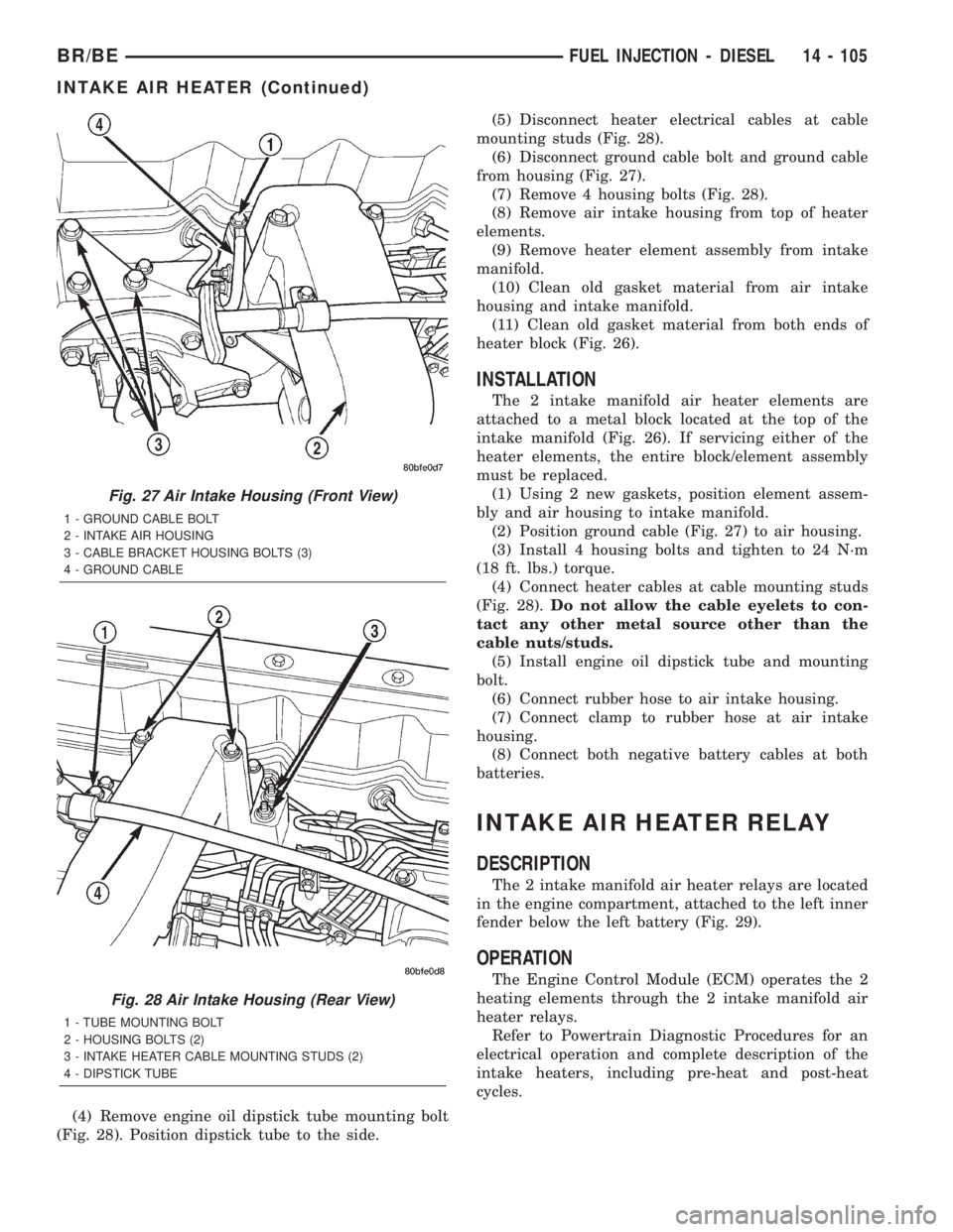
(4) Remove engine oil dipstick tube mounting bolt
(Fig. 28). Position dipstick tube to the side.(5) Disconnect heater electrical cables at cable
mounting studs (Fig. 28).
(6) Disconnect ground cable bolt and ground cable
from housing (Fig. 27).
(7) Remove 4 housing bolts (Fig. 28).
(8) Remove air intake housing from top of heater
elements.
(9) Remove heater element assembly from intake
manifold.
(10) Clean old gasket material from air intake
housing and intake manifold.
(11) Clean old gasket material from both ends of
heater block (Fig. 26).
INSTALLATION
The 2 intake manifold air heater elements are
attached to a metal block located at the top of the
intake manifold (Fig. 26). If servicing either of the
heater elements, the entire block/element assembly
must be replaced.
(1) Using 2 new gaskets, position element assem-
bly and air housing to intake manifold.
(2) Position ground cable (Fig. 27) to air housing.
(3) Install 4 housing bolts and tighten to 24 N´m
(18 ft. lbs.) torque.
(4) Connect heater cables at cable mounting studs
(Fig. 28).Do not allow the cable eyelets to con-
tact any other metal source other than the
cable nuts/studs.
(5) Install engine oil dipstick tube and mounting
bolt.
(6) Connect rubber hose to air intake housing.
(7) Connect clamp to rubber hose at air intake
housing.
(8) Connect both negative battery cables at both
batteries.
INTAKE AIR HEATER RELAY
DESCRIPTION
The 2 intake manifold air heater relays are located
in the engine compartment, attached to the left inner
fender below the left battery (Fig. 29).
OPERATION
The Engine Control Module (ECM) operates the 2
heating elements through the 2 intake manifold air
heater relays.
Refer to Powertrain Diagnostic Procedures for an
electrical operation and complete description of the
intake heaters, including pre-heat and post-heat
cycles.
Fig. 27 Air Intake Housing (Front View)
1 - GROUND CABLE BOLT
2 - INTAKE AIR HOUSING
3 - CABLE BRACKET HOUSING BOLTS (3)
4 - GROUND CABLE
Fig. 28 Air Intake Housing (Rear View)
1 - TUBE MOUNTING BOLT
2 - HOUSING BOLTS (2)
3 - INTAKE HEATER CABLE MOUNTING STUDS (2)
4 - DIPSTICK TUBE
BR/BEFUEL INJECTION - DIESEL 14 - 105
INTAKE AIR HEATER (Continued)
Page 1405 of 2255
REMOVAL
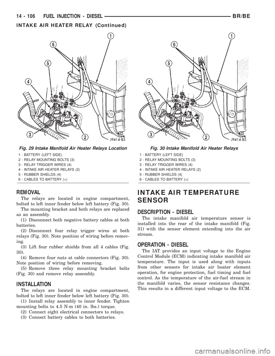
The relays are located in engine compartment,
bolted to left inner fender below left battery (Fig. 30).
The mounting bracket and both relays are replaced
as an assembly.
(1) Disconnect both negative battery cables at both
batteries.
(2) Disconnect four relay trigger wires at both
relays (Fig. 30). Note position of wiring before remov-
ing.
(3) Lift four rubber shields from all 4 cables (Fig.
30).
(4) Remove four nuts at cable connectors (Fig. 30).
Note position of wiring before removing.
(5) Remove three relay mounting bracket bolts
(Fig. 30) and remove relay assembly.
INSTALLATION
The relays are located in engine compartment,
bolted to left inner fender below left battery (Fig. 30).
(1) Install relay assembly to inner fender. Tighten
mounting bolts to 4.5 N´m (40 in. lbs.) torque.
(2) Connect eight electrical connectors to relays.
(3) Connect battery cables to both batteries.
INTAKE AIR TEMPERATURE
SENSOR
DESCRIPTION - DIESEL
The intake manifold air temperature sensor is
installed into the rear of the intake manifold (Fig.
31) with the sensor element extending into the air
stream.
OPERATION - DIESEL
The IAT provides an input voltage to the Engine
Control Module (ECM) indicating intake manifold air
temperature. The input is used along with inputs
from other sensors for intake air heater element
operation, for engine protection, fuel timing and fuel
control. As the temperature of the air-fuel stream in
the manifold varies, the sensor resistance changes.
This results in a different input voltage to the ECM.
Fig. 29 Intake Manifold Air Heater Relays Location
1 - BATTERY (LEFT SIDE)
2 - RELAY MOUNTING BOLTS (3)
3 - RELAY TRIGGER WIRES (4)
4 - INTAKE AIR HEATER RELAYS (2)
5 - RUBBER SHIELDS (4)
6 - CABLES TO BATTERY (+)
Fig. 30 Intake Manifold Air Heater Relays
1 - BATTERY (LEFT SIDE)
2 - RELAY MOUNTING BOLTS (3)
3 - RELAY TRIGGER WIRES (4)
4 - INTAKE AIR HEATER RELAYS (2)
5 - RUBBER SHIELDS (4)
6 - CABLES TO BATTERY (+)
14 - 106 FUEL INJECTION - DIESELBR/BE
INTAKE AIR HEATER RELAY (Continued)
Page 1406 of 2255
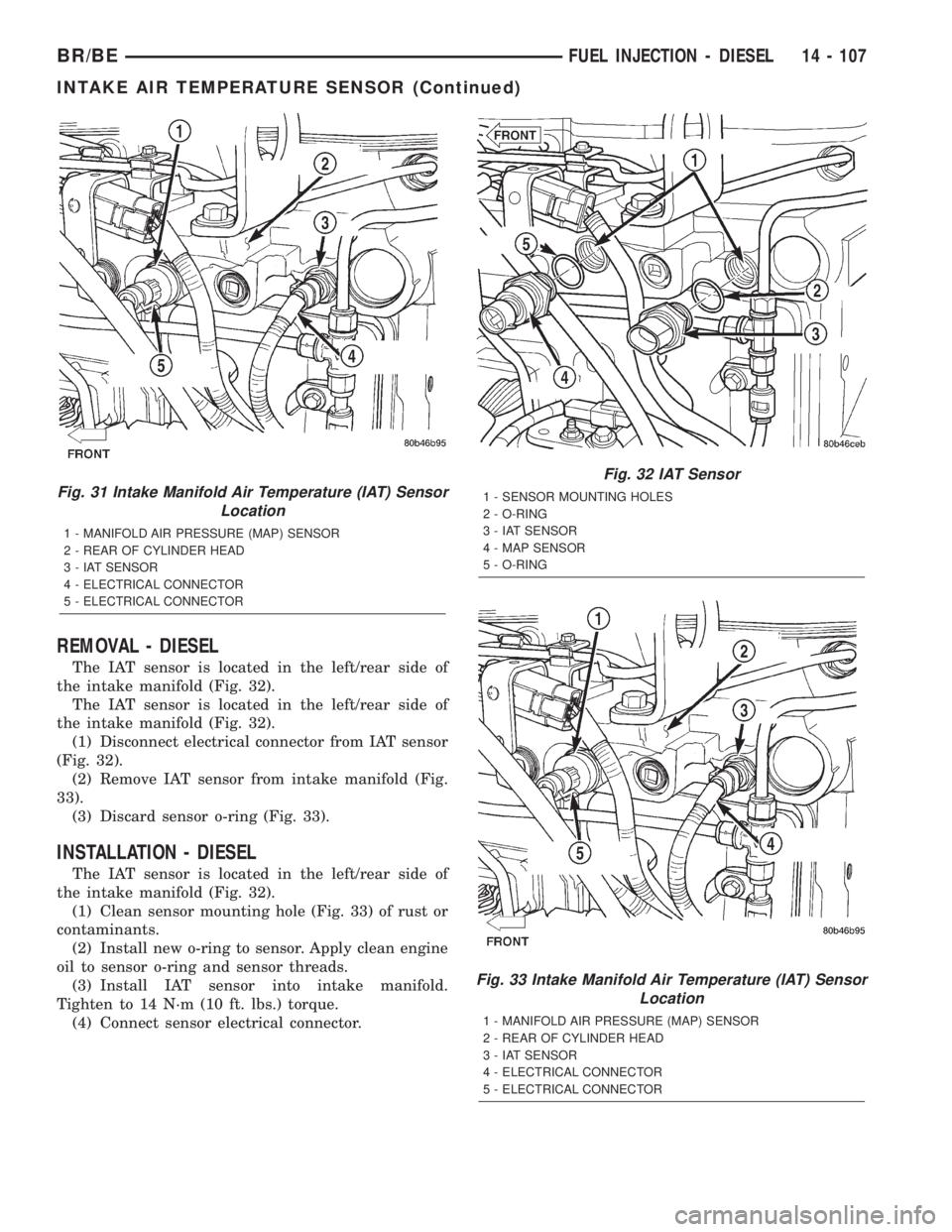
REMOVAL - DIESEL
The IAT sensor is located in the left/rear side of
the intake manifold (Fig. 32).
The IAT sensor is located in the left/rear side of
the intake manifold (Fig. 32).
(1) Disconnect electrical connector from IAT sensor
(Fig. 32).
(2) Remove IAT sensor from intake manifold (Fig.
33).
(3) Discard sensor o-ring (Fig. 33).
INSTALLATION - DIESEL
The IAT sensor is located in the left/rear side of
the intake manifold (Fig. 32).
(1) Clean sensor mounting hole (Fig. 33) of rust or
contaminants.
(2) Install new o-ring to sensor. Apply clean engine
oil to sensor o-ring and sensor threads.
(3) Install IAT sensor into intake manifold.
Tighten to 14 N´m (10 ft. lbs.) torque.
(4) Connect sensor electrical connector.
Fig. 31 Intake Manifold Air Temperature (IAT) Sensor
Location
1 - MANIFOLD AIR PRESSURE (MAP) SENSOR
2 - REAR OF CYLINDER HEAD
3 - IAT SENSOR
4 - ELECTRICAL CONNECTOR
5 - ELECTRICAL CONNECTOR
Fig. 32 IAT Sensor
1 - SENSOR MOUNTING HOLES
2 - O-RING
3 - IAT SENSOR
4 - MAP SENSOR
5 - O-RING
Fig. 33 Intake Manifold Air Temperature (IAT) Sensor
Location
1 - MANIFOLD AIR PRESSURE (MAP) SENSOR
2 - REAR OF CYLINDER HEAD
3 - IAT SENSOR
4 - ELECTRICAL CONNECTOR
5 - ELECTRICAL CONNECTOR
BR/BEFUEL INJECTION - DIESEL 14 - 107
INTAKE AIR TEMPERATURE SENSOR (Continued)
Page 1407 of 2255
MAP SENSOR
DESCRIPTION - DIESEL
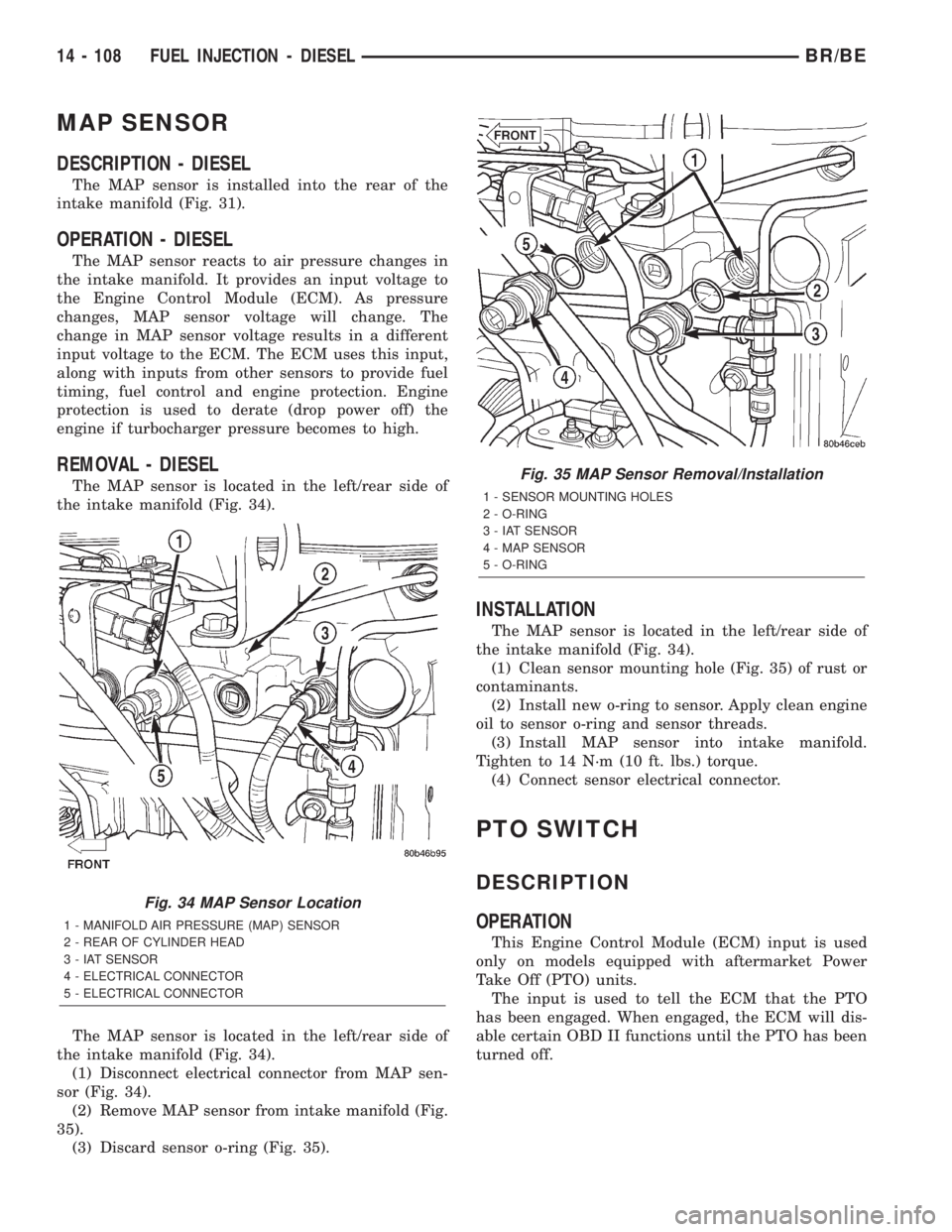
The MAP sensor is installed into the rear of the
intake manifold (Fig. 31).
OPERATION - DIESEL
The MAP sensor reacts to air pressure changes in
the intake manifold. It provides an input voltage to
the Engine Control Module (ECM). As pressure
changes, MAP sensor voltage will change. The
change in MAP sensor voltage results in a different
input voltage to the ECM. The ECM uses this input,
along with inputs from other sensors to provide fuel
timing, fuel control and engine protection. Engine
protection is used to derate (drop power off) the
engine if turbocharger pressure becomes to high.
REMOVAL - DIESEL
The MAP sensor is located in the left/rear side of
the intake manifold (Fig. 34).
The MAP sensor is located in the left/rear side of
the intake manifold (Fig. 34).
(1) Disconnect electrical connector from MAP sen-
sor (Fig. 34).
(2) Remove MAP sensor from intake manifold (Fig.
35).
(3) Discard sensor o-ring (Fig. 35).
INSTALLATION
The MAP sensor is located in the left/rear side of
the intake manifold (Fig. 34).
(1) Clean sensor mounting hole (Fig. 35) of rust or
contaminants.
(2) Install new o-ring to sensor. Apply clean engine
oil to sensor o-ring and sensor threads.
(3) Install MAP sensor into intake manifold.
Tighten to 14 N´m (10 ft. lbs.) torque.
(4) Connect sensor electrical connector.
PTO SWITCH
DESCRIPTION
OPERATION
This Engine Control Module (ECM) input is used
only on models equipped with aftermarket Power
Take Off (PTO) units.
The input is used to tell the ECM that the PTO
has been engaged. When engaged, the ECM will dis-
able certain OBD II functions until the PTO has been
turned off.
Fig. 34 MAP Sensor Location
1 - MANIFOLD AIR PRESSURE (MAP) SENSOR
2 - REAR OF CYLINDER HEAD
3 - IAT SENSOR
4 - ELECTRICAL CONNECTOR
5 - ELECTRICAL CONNECTOR
Fig. 35 MAP Sensor Removal/Installation
1 - SENSOR MOUNTING HOLES
2 - O-RING
3 - IAT SENSOR
4 - MAP SENSOR
5 - O-RING
14 - 108 FUEL INJECTION - DIESELBR/BE
Page 1415 of 2255
COLUMN
TABLE OF CONTENTS
page page
COLUMN
DESCRIPTION..........................6
OPERATION
SERVICE PRECAUTIONS................6
REMOVAL.............................6
INSTALLATION..........................8
SPECIFICATIONS
TORQUE CHART......................9
KEY-IN IGNITION SWITCH
DESCRIPTION..........................9
DIAGNOSIS AND TESTING - IGNITION
SWITCH AND KEY LOCK CYLINDER.......9
LOCK CYLINDER
REMOVAL.............................10INSTALLATION.........................10
IGNITION SWITCH
DESCRIPTION.........................11
OPERATION...........................11
DIAGNOSIS AND TESTING - IGNITION
SWITCH.............................11
REMOVAL.............................12
INSTALLATION.........................12
GEAR SHIFT LEVER
REMOVAL.............................14
INSTALLATION.........................15
STEERING WHEEL
REMOVAL.............................15
INSTALLATION.........................15
COLUMN
DESCRIPTION
The tilt and standard column (Fig. 1) has been
designed to be serviced as an assembly; less wiring,
switches, shrouds, steering wheel, etc. Most steering
column components can be serviced without remov-
ing the steering column from the vehicle.
OPERATION
SERVICE PRECAUTIONS
Safety goggles should be worn at all times when
working on steering columns.
To service the steering wheel, switches or the air-
bag, refer to the WARNINGS and CAUTIONS below.
WARNING: THE AIRBAG SYSTEM IS A SENSITIVE,
COMPLEX ELECTRO-MECHANICAL UNIT. BEFORE
ATTEMPTING TO DIAGNOSE, REMOVE OR INSTALL
THE AIRBAG SYSTEM COMPONENTS YOU MUST
FIRST DISCONNECT AND ISOLATE THE BATTERY
NEGATIVE (GROUND) CABLE. THEN WAIT TWO
MINUTES FOR THE SYSTEM CAPACITOR TO DIS-
CHARGE. FAILURE TO DO SO COULD RESULT IN
ACCIDENTAL DEPLOYMENT OF THE AIRBAG AND
POSSIBLE PERSONAL INJURY. THE FASTENERS,
SCREWS, AND BOLTS, ORIGINALLY USED FOR
THE AIRBAG COMPONENTS, HAVE SPECIAL COAT-INGS AND ARE SPECIFICALLY DESIGNED FOR THE
AIRBAG SYSTEM. THEY MUST NEVER BE
REPLACED WITH ANY SUBSTITUTES. ANYTIME A
NEW FASTENER IS NEEDED, REPLACE WITH THE
CORRECT FASTENERS PROVIDED IN THE SERVICE
PACKAGE OR FASTENERS LISTED IN THE PARTS
BOOKS.
CAUTION: Do not hammer on steering column shaft
or shift tube. This may cause the shaft/shift tube to
collapse or damage the bearing.
CAUTION: Do not attempt to remove the pivot pins
to disassemble the tilting mechanism. Do not
remove shaft lock plate, plate retainer, park lock
link or slider. This will damage the column (Fig. 2)
and (Fig. 3).
REMOVAL
(1) Position the front wheels straight ahead.
(2) Disconnect the negative (ground) cable from
the battery.
(3) Remove the airbag, (Refer to 8 - ELECTRICAL/
RESTRAINTS/DRIVER AIRBAG - REMOVAL).
(4) Remove the steering wheel with an appropriate
puller,(Refer to 19 - STEERING/COLUMN/STEER-
ING WHEEL - REMOVAL).
19 - 6 COLUMNBR/BE
Page 1418 of 2255
(3) Remove the shipping lock pin if necessary.
(4) Install the column through the floor pan.
(5) Position the column bracket breakaway cap-
sules on the mounting studs. Install, butloose
assemblethe two upper bracket nuts.
(6) With the front wheels in the straight-ahead
position. Align steering column shaft to the coupler.
Install anewpinch bolt and tighten to 49 N´m (36
ft. lbs.).
(7) Clip the wiring harness on the steering column.
Connect the multi- function switch wiring and
tighten with 7mm socket.
(8) Install the upper fixed shroud.
(9) Be sure both breakaway capsules are fully
seated in the slots in the column support bracket.
Pull the column rearward then tighten upper bracket
nuts to 12 N´m (105 in. lbs.).
(10) Tighten the toe plate to floor pan attaching
nuts to 22.5 N´m (200 in. lbs.).
(11) Install the wiring connections to the column.
Install the lower fixed shroud.
(12) Column shift vehicles, install the PRNDL
driver cable. Place shifter in Park position. If indica-tor needs adjusting, turn thumb screw on cable
retainer to adjust cable.
(13) Install the lock housing shrouds. Install the
tilt lever (if equipped).
(14) Install the knee blocker and steering column
opening cover, (Refer to 23 - BODY/INSTRUMENT
PANEL/STEERING COLUMN OPENING COVER -
INSTALLATION).
(15) Install steering wheel and tighten nut to 61
N´m (45 ft. lbs.), (Refer to 19 - STEERING/COL-
UMN/STEERING WHEEL - INSTALLATION).
(16) Install the airbag, (Refer to 8 - ELECTRICAL/
RESTRAINTS/DRIVER AIRBAG - INSTALLATION).
(17) Column shift vehicles, connect the shift link
rod to the transmission shift lever. Use multi-purpose
lubricant, or an equivalent product, to aid the instal-
lation.
(18) Install the battery ground (negative) cable.
(19) Verify operation of the automatic transmission
shift linkage and adjust as necessary, (Refer to 21 -
TRANSMISSION/TRANSAXLE/AUTOMATIC -
44RE/GEAR SHIFT CABLE - ADJUSTMENTS).
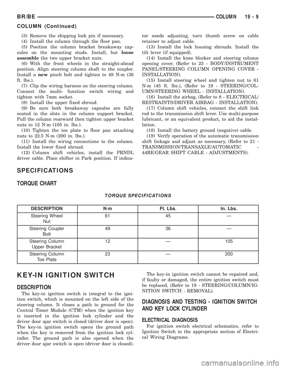
SPECIFICATIONS
TORQUE CHART
TORQUE SPECIFICATIONS
DESCRIPTION N´m Ft. Lbs. In. Lbs.
Steering Wheel
Nut61 45 Ð
Steering Coupler
Bolt49 36 Ð
Steering Column
Upper Bracket12 Ð 105
Steering Column
Toe Plate23 Ð 200
KEY-IN IGNITION SWITCH
DESCRIPTION
The key-in ignition switch is integral to the igni-
tion switch, which is mounted on the left side of the
steering column. It closes a path to ground for the
Central Timer Module (CTM) when the ignition key
is inserted in the ignition lock cylinder and the
driver door ajar switch is closed (driver door is open).
The key-in ignition switch opens the ground path
when the key is removed from the ignition lock cyl-
inder. The ground path is also opened when the
driver door ajar switch is open (driver door is closed).The key-in ignition switch cannot be repaired and,
if faulty or damaged, the entire ignition switch must
be replaced, (Refer to 19 - STEERING/COLUMN/IG-
NITION SWITCH - REMOVAL).
DIAGNOSIS AND TESTING - IGNITION SWITCH
AND KEY LOCK CYLINDER
ELECTRICAL DIAGNOSIS
For ignition switch electrical schematics, refer to
Ignition Switch in the appropriate section of Electri-
cal Wiring Diagrams.
BR/BECOLUMN 19 - 9
COLUMN (Continued)