Page 1438 of 2255
(8) Install adjuster nut and lock nut.
(9) Adjust Thrust Bearing Preload and Over-Cen-
ter Rotating Torque, (Refer to 19 - STEERING/GEAR
- ADJUSTMENTS).
STEERING GEAR HOUSING
PLUG
REMOVAL
(1) Unseat and remove retaining ring from groove
with a punch through the hole in the end of the
housing (Fig. 32).
(2) Slowly rotate stub shaft with 12 point socket
COUNTER-CLOCKWISE to force the end plug out
from housing.
CAUTION: Do not turn stub shaft any further than
necessary. The rack piston balls will drop out of the
rack piston circuit if the stub shaft is turned too far.
(3) Remove O-ring from the housing (Fig. 33).
Fig. 31 Stub Shaft Cap O-Ring
1 - VALVE BODY
2 - STUB SHAFT CAP
3 - O-RING
Fig. 32 End Plug Retaining Ring
1 - RETAINING RING
Fig. 33 End Plug Components
1 - HOUSING ASSEMBLY
2 - HOUSING END PLUG O-RING SEAL
3 - HOUSING END PLUG
4 - RETAINING RING
BR/BEGEAR 19 - 29
SPOOL VALVE (Continued)
Page 1441 of 2255
CAUTION: The rack piston balls must be installed
alternately into the rack piston and ball guide. This
maintains worm shaft preload. There are 12 black
balls and 12 silver (Chrome) balls. The black balls
are smaller than the silver balls.
(4) Lubricate and install rack piston balls through
return guide hole while turning worm shaft COUN-
TERCLOCKWISE (Fig. 40).
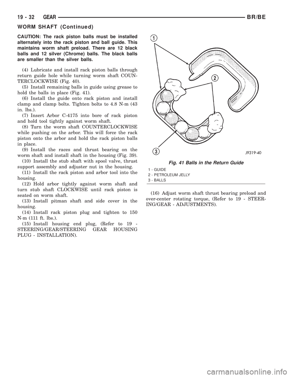
(5) Install remaining balls in guide using grease to
hold the balls in place (Fig. 41).
(6) Install the guide onto rack piston and install
clamp and clamp bolts. Tighten bolts to 4.8 N´m (43
in. lbs.).
(7) Insert Arbor C-4175 into bore of rack piston
and hold tool tightly against worm shaft.
(8) Turn the worm shaft COUNTERCLOCKWISE
while pushing on the arbor. This will force the rack
piston onto the arbor and hold the rack piston balls
in place.
(9) Install the races and thrust bearing on the
worm shaft and install shaft in the housing (Fig. 39).
(10) Install the stub shaft with spool valve, thrust
support assembly and adjuster nut in the housing.
(11) Install the rack piston and arbor tool into the
housing.
(12) Hold arbor tightly against worm shaft and
turn stub shaft CLOCKWISE until rack piston is
seated on worm shaft.
(13) Install pitman shaft and side cover in the
housing.
(14) Install rack piston plug and tighten to 150
N´m (111 ft. lbs.).
(15) Install housing end plug, (Refer to 19 -
STEERING/GEAR/STEERING GEAR HOUSING
PLUG - INSTALLATION).(16) Adjust worm shaft thrust bearing preload and
over-center rotating torque, (Refer to 19 - STEER-
ING/GEAR - ADJUSTMENTS).
Fig. 41 Balls in the Return Guide
1 - GUIDE
2 - PETROLEUM JELLY
3 - BALLS
19 - 32 GEARBR/BE
WORM SHAFT (Continued)
Page 1449 of 2255
LINKAGE - 2WD
TABLE OF CONTENTS
page page
LINKAGE - 2WD
DESCRIPTION.........................40
STANDARD PROCEDURE - LUBRICATION....40
REMOVAL.............................40
INSTALLATION.........................41SPECIFICATIONS
TORQUE CHART......................41
SPECIAL TOOLS
STEERING LINKAGE...................41
LINKAGE - 2WD
DESCRIPTION
Light duty (LD) and heavy duty (HD) steering link-
age is used with IFS suspensions. The linkage is
comprised of a idler arm, pitman arm, center link
and tie rod ends. Heavy duty linkage is used on 8800
and 10500 lb. GVW vehicles.
CAUTION: If any steering components are replaced
or serviced an alignment must be performed.
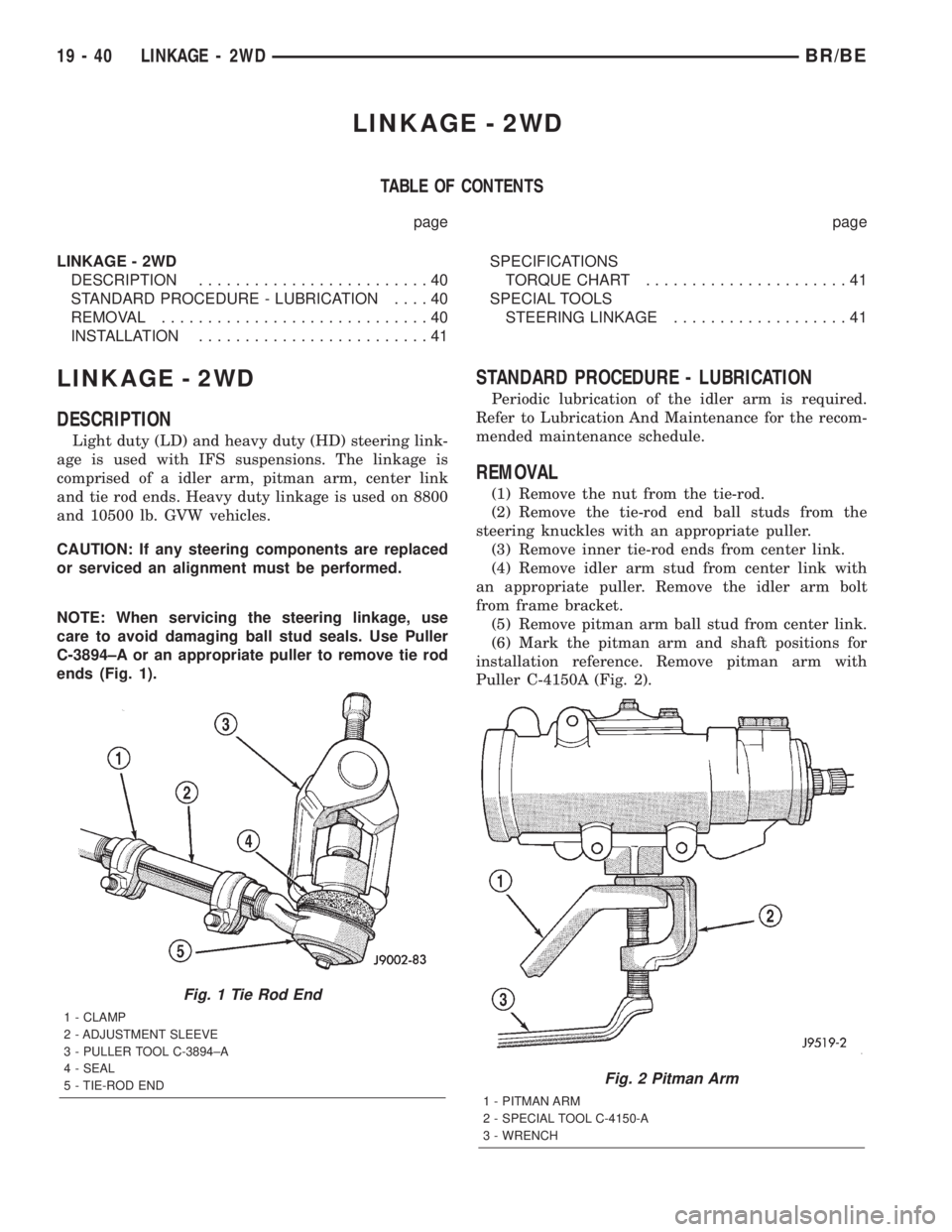
NOTE: When servicing the steering linkage, use
care to avoid damaging ball stud seals. Use Puller
C-3894±A or an appropriate puller to remove tie rod
ends (Fig. 1).
STANDARD PROCEDURE - LUBRICATION
Periodic lubrication of the idler arm is required.
Refer to Lubrication And Maintenance for the recom-
mended maintenance schedule.
REMOVAL
(1) Remove the nut from the tie-rod.
(2) Remove the tie-rod end ball studs from the
steering knuckles with an appropriate puller.
(3) Remove inner tie-rod ends from center link.
(4) Remove idler arm stud from center link with
an appropriate puller. Remove the idler arm bolt
from frame bracket.
(5) Remove pitman arm ball stud from center link.
(6) Mark the pitman arm and shaft positions for
installation reference. Remove pitman arm with
Puller C-4150A (Fig. 2).
Fig. 1 Tie Rod End
1 - CLAMP
2 - ADJUSTMENT SLEEVE
3 - PULLER TOOL C-3894±A
4 - SEAL
5 - TIE-ROD END
Fig. 2 Pitman Arm
1 - PITMAN ARM
2 - SPECIAL TOOL C-4150-A
3 - WRENCH
19 - 40 LINKAGE - 2WDBR/BE
Page 1450 of 2255
INSTALLATION
(1) Position idler arm on the frame bracket and
tighten the bolt to specification.
(2) Center steering gear to alignment marks and
install pitman arm.
(3)
Install the lock washer and retaining nut on the
pitman shaft. Tighten the nut to 251 N´m (185 ft. lbs.).
(4) Install center link to ball studs and tighten
retaining nuts to specification.
(5) Install tie-rod ends into center link and tighten
the nuts to 88 N´m (65 ft. lbs.). Install new nuts.(6) Install tie-rod ends into steering knuckles and
tighten nuts to 108 N´m (80 ft. lbs.).
(7) Remove the supports and lower the vehicle to
the surface. Center steering wheel and adjust toe,
(Refer to 2 - SUSPENSION/WHEEL ALIGNMENT -
STANDARD PROCEDURE).
NOTE: Position the clamp on the sleeve so retain-
ing bolt is located on the bottom side of the sleeve.
(8) After adjustment, tighten the tie-rod adjust-
ment sleeve clamp bolt to 61 N´m (45 ft. lbs.).
SPECIFICATIONS
TORQUE CHART
TORQUE SPECIFICATIONS
DESCRIPTION N´m Ft. Lbs. In. Lbs.
Pitman Arm
Gear Nut250 185 Ð
Pitman Arm
Center Link Nut11 5 8 5 Ð
Idler Arm
Mounting Bolts271 200 Ð
Idler Arm
Center Link Nut88 65 Ð
Tie Rod
Knuckle Nut108 80 Ð
Tie Rod
Center Link Nut88 65 Ð
Tie Rod
Adjuster Clamp61 45 Ð
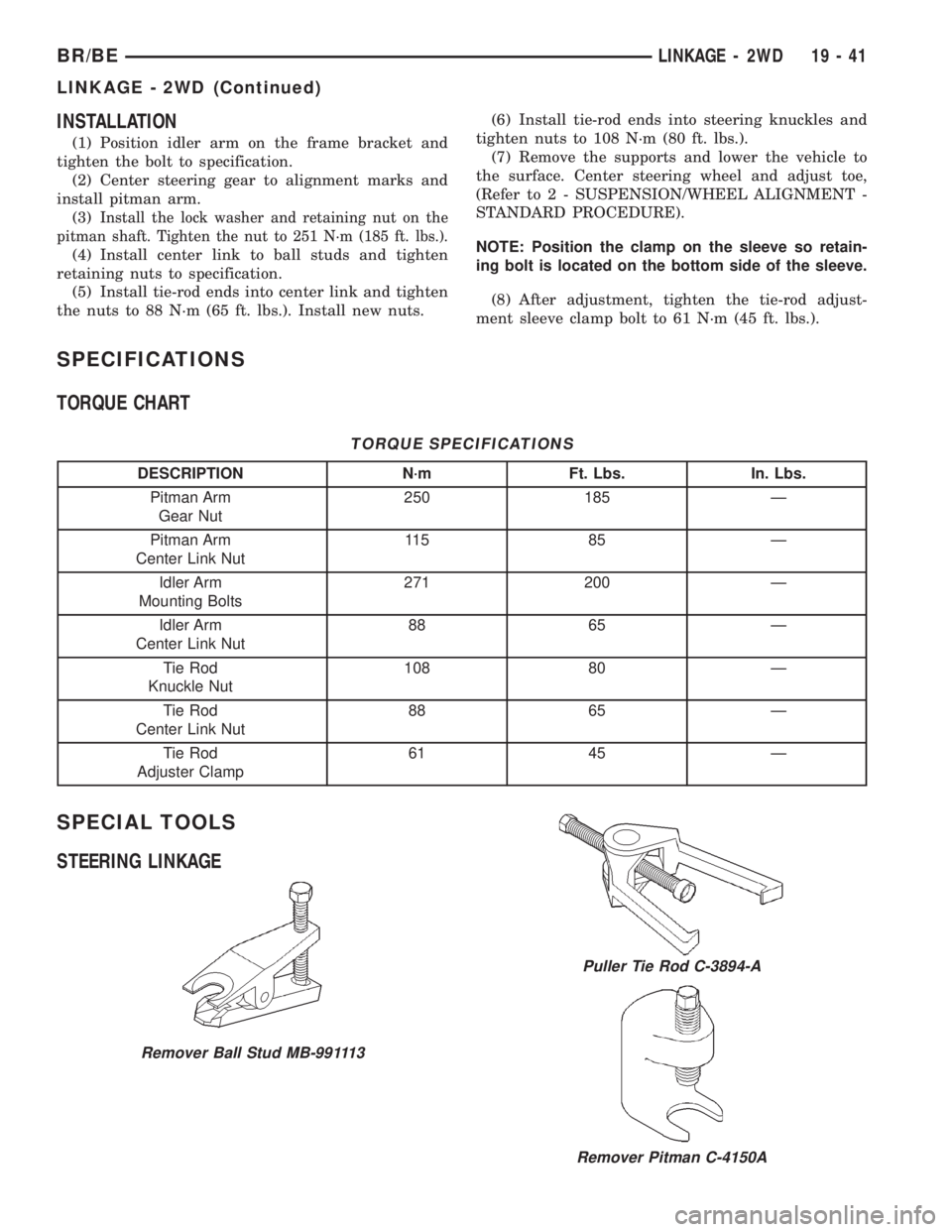
SPECIAL TOOLS
STEERING LINKAGE
Remover Ball Stud MB-991113
Puller Tie Rod C-3894-A
Remover Pitman C-4150A
BR/BELINKAGE - 2WD 19 - 41
LINKAGE - 2WD (Continued)
Page 1451 of 2255
LINKAGE - 4WD
TABLE OF CONTENTS
page page
LINKAGE - 4WD
DESCRIPTION.........................42
STANDARD PROCEDURE - LUBRICATION....42
REMOVAL.............................42
INSTALLATION.........................43SPECIFICATIONS
TORQUE CHART......................43
SPECIAL TOOLS
STEERING LINKAGE...................44
LINKAGE - 4WD
DESCRIPTION
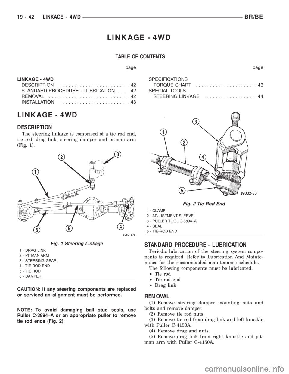
The steering linkage is comprised of a tie rod end,
tie rod, drag link, steering damper and pitman arm
(Fig. 1).
CAUTION: If any steering components are replaced
or serviced an alignment must be performed.
NOTE: To avoid damaging ball stud seals, use
Puller C-3894±A or an appropriate puller to remove
tie rod ends (Fig. 2).
STANDARD PROCEDURE - LUBRICATION
Periodic lubrication of the steering system compo-
nents is required. Refer to Lubrication And Mainte-
nance for the recommended maintenance schedule.
The following components must be lubricated:
²Tie rod
²Tie rod end
²Drag link
REMOVAL
(1) Remove steering damper mounting nuts and
bolts and remove damper.
(2) Remove tie rod nuts.
(3) Remove tie rod from drag link and left knuckle
with Puller C-4150A.
(4) Remove drag and nuts.
(5) Remove drag link from right knuckle and pit-
man arm with Puller C-4150A.
Fig. 1 Steering Linkage
1 - DRAG LINK
2 - PITMAN ARM
3 - STEERING GEAR
4 - TIE ROD END
5 - TIE ROD
6 - DAMPER
Fig. 2 Tie Rod End
1 - CLAMP
2 - ADJUSTMENT SLEEVE
3 - PULLER TOOL C-3894±A
4 - SEAL
5 - TIE-ROD END
19 - 42 LINKAGE - 4WDBR/BE
Page 1452 of 2255
(6) Mark the pitman arm and shaft positions for
installation reference. Remove the nut and washer
from the pitman arm. Remove the pitman arm with
Puller C-4150A.
INSTALLATION
(1) Align reference marks and install pitman arm.
(2) Install the lock washer and retaining nut on
the pitman shaft and tighten nut to 251 N´m (185 ft.
lbs.).
(3) Install drag link to the pitman arm. Install the
nut and tighten to 108 N´m (80 ft. lbs.).
(4) Install drag link to the right steering knuckle.
Install the nut and tighten to 88 N´m (65 ft. lbs.).
(5) Install tie rod to the left steering knuckle and
drag link. Install the nuts and tighten to 108 N´m
(80 ft. lbs.).(6) Install steering damper on the axle. Tighten
nut to 95 N´m (75 ft. lbs.).
(7) Install steering damper on the tie rod. Tighten
nut to 81 N´m (60 ft. lbs.).
(8) Remove the supports and lower the vehicle to
the surface. Center steering wheel and adjust toe,
refer to Group 2 Suspension.
(9) After adjustment tighten tie rod adjustment
sleeve clamp bolts to 61 N´m (45 ft. lbs.).
NOTE: Position the clamp on the sleeve so retain-
ing bolt is located on the bottom side of the sleeve.
SPECIFICATIONS
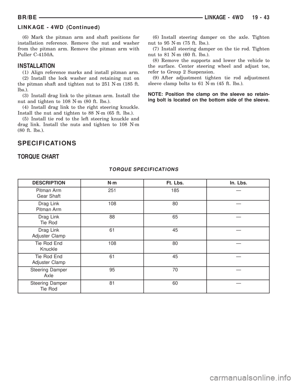
TORQUE CHART
TORQUE SPECIFICATIONS
DESCRIPTION N´m Ft. Lbs. In. Lbs.
Pitman Arm
Gear Shaft251 185 Ð
Drag Link
Pitman Arm108 80 Ð
Drag Link
Tie Rod88 65 Ð
Drag Link
Adjuster Clamp61 45 Ð
Tie Rod End
Knuckle108 80 Ð
Tie Rod End
Adjuster Clamp61 45 Ð
Steering Damper
Axle95 70 Ð
Steering Damper
Tie Rod81 60 Ð
BR/BELINKAGE - 4WD 19 - 43
LINKAGE - 4WD (Continued)
Page 1489 of 2255
(7) Hold mainshaft Socket 6993 4X2 or Socket
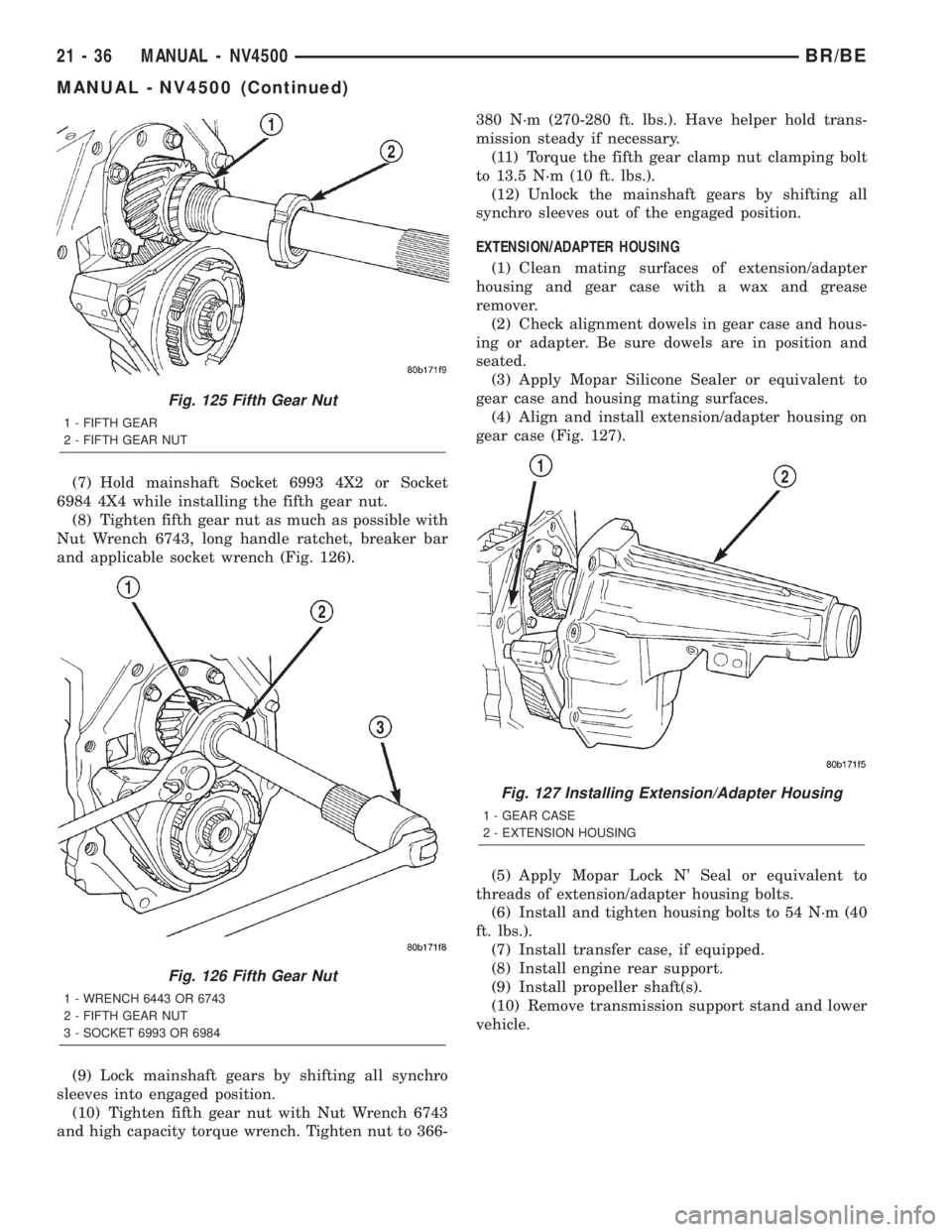
6984 4X4 while installing the fifth gear nut.
(8) Tighten fifth gear nut as much as possible with
Nut Wrench 6743, long handle ratchet, breaker bar
and applicable socket wrench (Fig. 126).
(9) Lock mainshaft gears by shifting all synchro
sleeves into engaged position.
(10) Tighten fifth gear nut with Nut Wrench 6743
and high capacity torque wrench. Tighten nut to 366-380 N´m (270-280 ft. lbs.). Have helper hold trans-
mission steady if necessary.
(11) Torque the fifth gear clamp nut clamping bolt
to 13.5 N´m (10 ft. lbs.).
(12) Unlock the mainshaft gears by shifting all
synchro sleeves out of the engaged position.
EXTENSION/ADAPTER HOUSING
(1) Clean mating surfaces of extension/adapter
housing and gear case with a wax and grease
remover.
(2) Check alignment dowels in gear case and hous-
ing or adapter. Be sure dowels are in position and
seated.
(3) Apply Mopar Silicone Sealer or equivalent to
gear case and housing mating surfaces.
(4) Align and install extension/adapter housing on
gear case (Fig. 127).
(5) Apply Mopar Lock N' Seal or equivalent to
threads of extension/adapter housing bolts.
(6) Install and tighten housing bolts to 54 N´m (40
ft. lbs.).
(7) Install transfer case, if equipped.
(8) Install engine rear support.
(9) Install propeller shaft(s).
(10) Remove transmission support stand and lower
vehicle.
Fig. 125 Fifth Gear Nut
1 - FIFTH GEAR
2 - FIFTH GEAR NUT
Fig. 126 Fifth Gear Nut
1 - WRENCH 6443 OR 6743
2 - FIFTH GEAR NUT
3 - SOCKET 6993 OR 6984
Fig. 127 Installing Extension/Adapter Housing
1 - GEAR CASE
2 - EXTENSION HOUSING
21 - 36 MANUAL - NV4500BR/BE
MANUAL - NV4500 (Continued)
Page 1491 of 2255
(18) Install the bolts to hold the shift tower to the
isolator plate and the shift cover. Tighten the shift
tower bolts to 10.2±11.25 N´m (7.5±8.3 ft. lbs.).
(19) Install the shift lever extension onto the shift
tower and lever assembly.(20) Install shift lever boot and bezel.
(21) Connect battery negative cable.
SPECIFICATIONS
TORQUE SPECIFICATIONS
DESCRIPTION N´m Ft. Lbs. In. Lbs.
Switch, Back-up Lamp 22-34 16-25 -
Countershaft Bearing
Plate Bolts19-26 14-19 170-230
Fifth Gear Nut 366-380 270-280 -
Fifth Gear Nut Clamp Bolt 13.5 10 -
Drain and Fill Plug 34-47 25-35 -
Front Bearing Retainer
Bolts27-34 20-25 235-305
Mainshaft Bearing Plate
Bolts19-26 14-19 170-230
PTO Cover Bolts 27-54 20-40 -
Extension/Adapter
Housing Bolts41-68 30-50 -
Shift Cover Bolt 27-31 20-23 -
SPECIAL TOOLS
Remover Seal C-3985-B
Remover Bushing 6957
Remover, BushingÐ8155
Installer Bushing 6951
21 - 38 MANUAL - NV4500BR/BE
MANUAL - NV4500 (Continued)