2002 DODGE RAM torque
[x] Cancel search: torquePage 1382 of 2255
REMOVAL
(1) Drain and remove fuel tank. Refer to Fuel
Tank Removal/Installation.
(2) Thoroughly clean area around tank module at
top of tank.
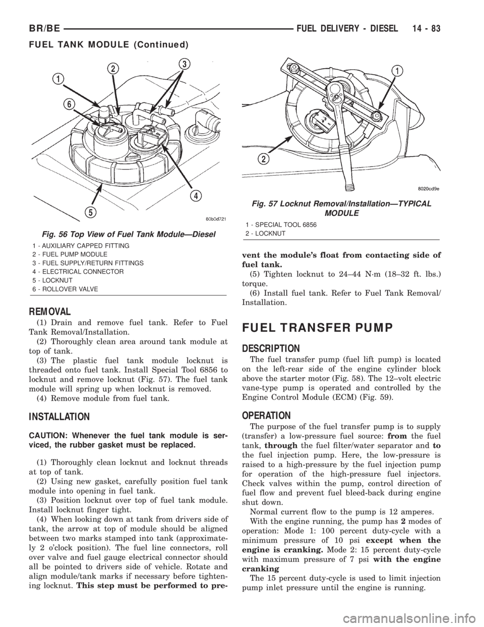
(3) The plastic fuel tank module locknut is
threaded onto fuel tank. Install Special Tool 6856 to
locknut and remove locknut (Fig. 57). The fuel tank
module will spring up when locknut is removed.
(4) Remove module from fuel tank.
INSTALLATION
CAUTION: Whenever the fuel tank module is ser-
viced, the rubber gasket must be replaced.
(1) Thoroughly clean locknut and locknut threads
at top of tank.
(2) Using new gasket, carefully position fuel tank
module into opening in fuel tank.
(3) Position locknut over top of fuel tank module.
Install locknut finger tight.
(4) When looking down at tank from drivers side of
tank, the arrow at top of module should be aligned
between two marks stamped into tank (approximate-
ly 2 o'clock position). The fuel line connectors, roll
over valve and fuel gauge electrical connector should
all be pointed to drivers side of vehicle. Rotate and
align module/tank marks if necessary before tighten-
ing locknut.This step must be performed to pre-vent the module's float from contacting side of
fuel tank.
(5) Tighten locknut to 24±44 N´m (18±32 ft. lbs.)
torque.
(6) Install fuel tank. Refer to Fuel Tank Removal/
Installation.
FUEL TRANSFER PUMP
DESCRIPTION
The fuel transfer pump (fuel lift pump) is located
on the left-rear side of the engine cylinder block
above the starter motor (Fig. 58). The 12±volt electric
vane-type pump is operated and controlled by the
Engine Control Module (ECM) (Fig. 59).
OPERATION
The purpose of the fuel transfer pump is to supply
(transfer) a low-pressure fuel source:fromthe fuel
tank,throughthe fuel filter/water separator andto
the fuel injection pump. Here, the low-pressure is
raised to a high-pressure by the fuel injection pump
for operation of the high-pressure fuel injectors.
Check valves within the pump, control direction of
fuel flow and prevent fuel bleed-back during engine
shut down.
Normal current flow to the pump is 12 amperes.
With the engine running, the pump has2modes of
operation: Mode 1: 100 percent duty-cycle with a
minimum pressure of 10 psiexcept when the
engine is cranking.Mode 2: 15 percent duty-cycle
with maximum pressure of 7 psiwith the engine
cranking
The 15 percent duty-cycle is used to limit injection
pump inlet pressure until the engine is running.
Fig. 56 Top View of Fuel Tank ModuleÐDiesel
1 - AUXILIARY CAPPED FITTING
2 - FUEL PUMP MODULE
3 - FUEL SUPPLY/RETURN FITTINGS
4 - ELECTRICAL CONNECTOR
5 - LOCKNUT
6 - ROLLOVER VALVE
Fig. 57 Locknut Removal/InstallationÐTYPICAL
MODULE
1 - SPECIAL TOOL 6856
2 - LOCKNUT
BR/BEFUEL DELIVERY - DIESEL 14 - 83
FUEL TANK MODULE (Continued)
Page 1386 of 2255
(2) Thoroughly clean area around transfer pump
and fuel lines of any contamination.
(3) Remove starter motor. Refer to Starter Remov-
al/Installation in 8, Starting System for procedures.
(4) Place a drain pan below the pump.
(5) Disconnect fuel line quick-connect fitting at
fuel supply line (Fig. 64) at rear of pump.
(6) Remove support bracket bolt at top of pump
(Fig. 64).
(7) Remove front and rear banjo bolts at pump
(Fig. 64).
(8) Disconnect electrical connector at side of pump
(Fig. 64).
(9) Remove three pump bracket nuts (Fig. 64) and
remove pump from vehicle.
INSTALLATION
The fuel transfer pump (fuel lift pump) is located
on left side of engine, below and rearward of fuel fil-
ter (Fig. 64).
(1) Install new gaskets to fuel supply line/support
bracket and banjo bolt at rear of pump. Install line
and banjo bolt to pump.Do nottighten banjo bolt at
this time.
(2) Install new gaskets to fuel line and banjo bolt
at front of pump.
(3) Position 3 pump studs into pump mounting
bracket and install 3 nuts.Do nottighten nuts at
this time.
(4) Install support bracket bolt (Fig. 64).Do not
tighten bolt at this time.
(5) Tighten 3 pump nuts to 12 N´m (9 ft. lbs.)
torque.
(6) Tighten both banjo bolts to 24 N´m (18 ft. lbs.)
torque.
(7) Tighten support bracket bolt 12 N´m (9 ft. lbs.)
torque.
(8) Connect electrical connector to pump (Fig. 64).
(9) Connect fuel line quick-connect fitting to fuel
supply line at rear of pump.
(10) Install starter motor. Refer to Starter Remov-
al/Installation in 8, Starting for procedures.
(11) Connect both negative battery cables at both
batteries.
(12) Bleed air at fuel supply line at side of fuel
injection pump. Refer to the Air Bleed Procedure.
(13) Start engine and check for leaks.
OVERFLOW VALVE
DESCRIPTION
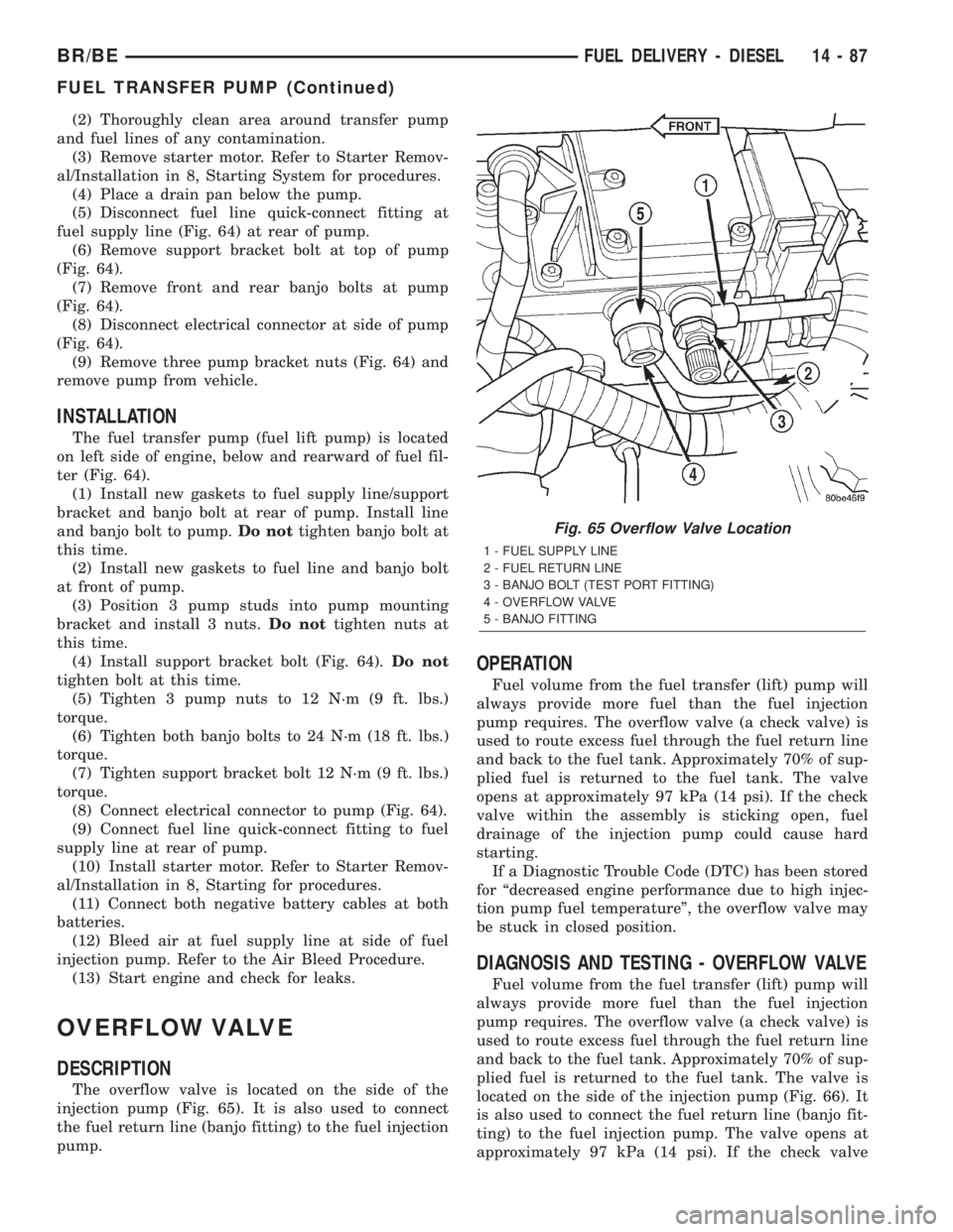
The overflow valve is located on the side of the
injection pump (Fig. 65). It is also used to connect
the fuel return line (banjo fitting) to the fuel injection
pump.
OPERATION
Fuel volume from the fuel transfer (lift) pump will
always provide more fuel than the fuel injection
pump requires. The overflow valve (a check valve) is
used to route excess fuel through the fuel return line
and back to the fuel tank. Approximately 70% of sup-
plied fuel is returned to the fuel tank. The valve
opens at approximately 97 kPa (14 psi). If the check
valve within the assembly is sticking open, fuel
drainage of the injection pump could cause hard
starting.
If a Diagnostic Trouble Code (DTC) has been stored
for ªdecreased engine performance due to high injec-
tion pump fuel temperatureº, the overflow valve may
be stuck in closed position.
DIAGNOSIS AND TESTING - OVERFLOW VALVE
Fuel volume from the fuel transfer (lift) pump will
always provide more fuel than the fuel injection
pump requires. The overflow valve (a check valve) is
used to route excess fuel through the fuel return line
and back to the fuel tank. Approximately 70% of sup-
plied fuel is returned to the fuel tank. The valve is
located on the side of the injection pump (Fig. 66). It
is also used to connect the fuel return line (banjo fit-
ting) to the fuel injection pump. The valve opens at
approximately 97 kPa (14 psi). If the check valve
Fig. 65 Overflow Valve Location
1 - FUEL SUPPLY LINE
2 - FUEL RETURN LINE
3 - BANJO BOLT (TEST PORT FITTING)
4 - OVERFLOW VALVE
5 - BANJO FITTING
BR/BEFUEL DELIVERY - DIESEL 14 - 87
FUEL TRANSFER PUMP (Continued)
Page 1387 of 2255
within the assembly is sticking, low engine power or
hard starting may result.
If a Diagnostic Trouble Code (DTC) has been stored
for ªdecreased engine performance due to high injec-
tion pump fuel temperatureº, the overflow valve may
be stuck in closed position.
A rubber tipped blow gun with regulated air line
pressure is needed for this test.
(1) Clean area around overflow valve and fuel
return line at injection pump before removal.
(2) Remove valve from pump and banjo fitting.
(3) Discard old sealing gaskets.
(4) Set regulated air pressure to approximately 97
kPa (14±16 psi).
(5) Using blow gun, apply pressure to overflow
valve inlet end (end that goes into injection pump).
(6) Internal check valve should release, and air
should pass through valve at 97 kPa (14±16 psi). If
not, replace valve.
(7) Reduce regulated air pressure to 10 psi and
observe valve. Valve should stay shut. If not, replace
valve.
(8) Install new sealing gaskets to valve.
(9) Install valve through banjo fitting and into
pump.
(10) Tighten to 30 N´m (24 ft. lbs.) torque.REMOVAL
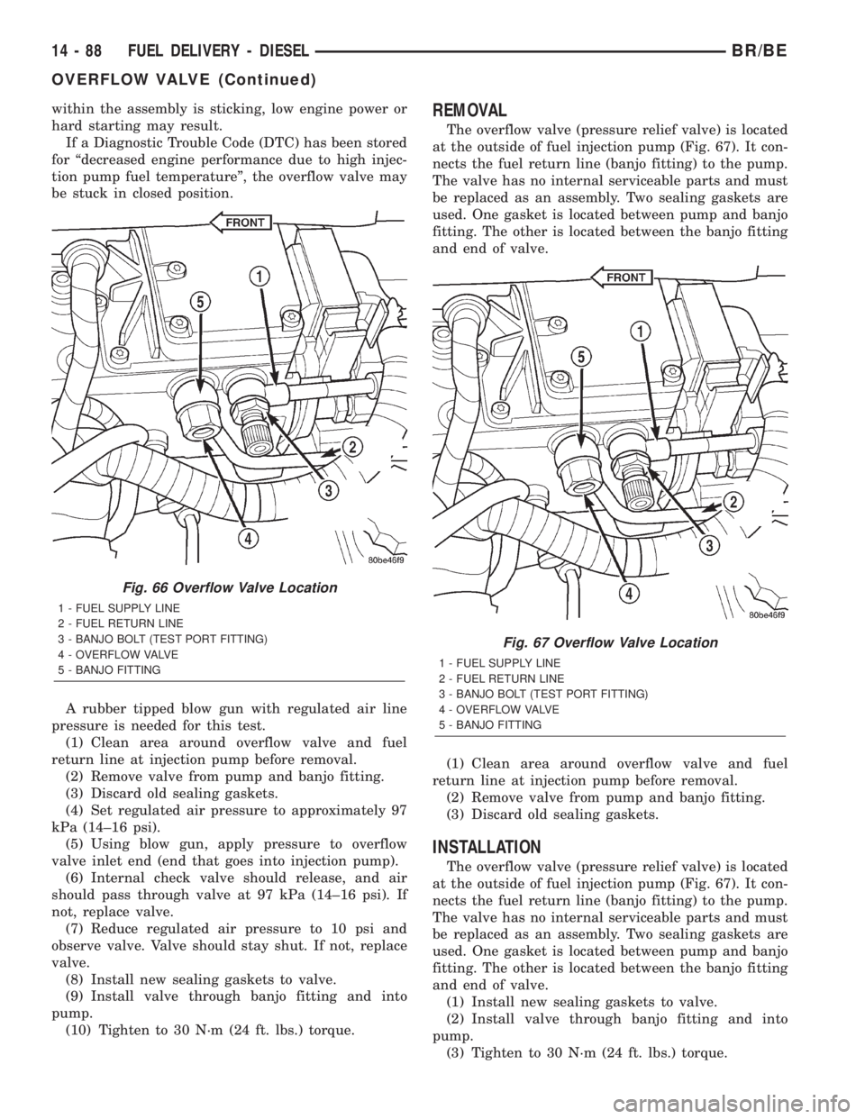
The overflow valve (pressure relief valve) is located
at the outside of fuel injection pump (Fig. 67). It con-
nects the fuel return line (banjo fitting) to the pump.
The valve has no internal serviceable parts and must
be replaced as an assembly. Two sealing gaskets are
used. One gasket is located between pump and banjo
fitting. The other is located between the banjo fitting
and end of valve.
(1) Clean area around overflow valve and fuel
return line at injection pump before removal.
(2) Remove valve from pump and banjo fitting.
(3) Discard old sealing gaskets.
INSTALLATION
The overflow valve (pressure relief valve) is located
at the outside of fuel injection pump (Fig. 67). It con-
nects the fuel return line (banjo fitting) to the pump.
The valve has no internal serviceable parts and must
be replaced as an assembly. Two sealing gaskets are
used. One gasket is located between pump and banjo
fitting. The other is located between the banjo fitting
and end of valve.
(1) Install new sealing gaskets to valve.
(2) Install valve through banjo fitting and into
pump.
(3) Tighten to 30 N´m (24 ft. lbs.) torque.
Fig. 66 Overflow Valve Location
1 - FUEL SUPPLY LINE
2 - FUEL RETURN LINE
3 - BANJO BOLT (TEST PORT FITTING)
4 - OVERFLOW VALVE
5 - BANJO FITTING
Fig. 67 Overflow Valve Location
1 - FUEL SUPPLY LINE
2 - FUEL RETURN LINE
3 - BANJO BOLT (TEST PORT FITTING)
4 - OVERFLOW VALVE
5 - BANJO FITTING
14 - 88 FUEL DELIVERY - DIESELBR/BE
OVERFLOW VALVE (Continued)
Page 1389 of 2255
REMOVAL
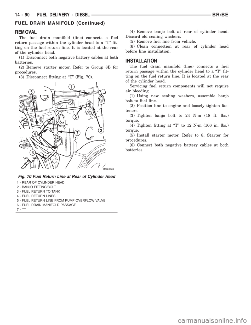
The fuel drain manifold (line) connects a fuel
return passage within the cylinder head to a ªTº fit-
ting on the fuel return line. It is located at the rear
of the cylinder head.
(1) Disconnect both negative battery cables at both
batteries.
(2) Remove starter motor. Refer to Group 8B for
procedures.
(3) Disconnect fitting at ªTº (Fig. 70).(4) Remove banjo bolt at rear of cylinder head.
Discard old sealing washers.
(5) Remove fuel line from vehicle.
(6) Clean connection at rear of cylinder head
before line installation.
INSTALLATION
The fuel drain manifold (line) connects a fuel
return passage within the cylinder head to a ªTº fit-
ting on the fuel return line. It is located at the rear
of the cylinder head.
Servicing fuel return components will not require
air bleeding.
(1) Using new sealing washers, assemble banjo
bolt to fuel line.
(2) Position line to engine and loosely tighten fas-
teners.
(3) Tighten banjo bolt to 24 N´m (18 ft. lbs.)
torque.
(4) Tighten fitting at ªTº to 12 N´m (106 in. lbs.)
torque.
(5) Install starter motor. Refer to 8, Starter for
procedures.
(6) Connect both negative battery cables at both
batteries.
Fig. 70 Fuel Return Line at Rear of Cylinder Head
1 - REAR OF CYLINDER HEAD
2 - BANJO FITTING/BOLT
3 - FUEL RETURN TO TANK
4 - FUEL RETURN LINES
5 - FUEL RETURN LINE FROM PUMP OVERFLOW VALVE
6 - FUEL DRAIN MANIFOLD PASSAGE
7 - ªTº
14 - 90 FUEL DELIVERY - DIESELBR/BE
FUEL DRAIN MANIFOLD (Continued)
Page 1390 of 2255
FUEL INJECTION - DIESEL
TABLE OF CONTENTS
page page
FUEL INJECTION - DIESEL
DESCRIPTION - DIESEL FUEL INJECTION
SYSTEM............................91
DIAGNOSIS AND TESTING - BOOST
PRESSURE..........................93
SPECIFICATIONS
TORQUE - DIESEL ENGINE.............94
ACCELERATOR PEDAL POSITION SENSOR
DESCRIPTION.........................95
OPERATION...........................95
REMOVAL.............................95
INSTALLATION.........................97
FUEL INJECTOR
DESCRIPTION.........................97
OPERATION...........................98
DIAGNOSIS AND TESTINGÐFUEL INJECTOR
TEST...............................99
REMOVAL............................101
INSTALLATION........................102
FUEL INJECTION PUMP RELAY
DESCRIPTION........................103
OPERATION..........................103
FUEL TEMPERATURE SENSOR
DESCRIPTION........................104
OPERATION..........................104
INTAKE AIR HEATER
DESCRIPTION........................104OPERATION..........................104
REMOVAL............................104
INSTALLATION........................105
INTAKE AIR HEATER RELAY
DESCRIPTION........................105
OPERATION..........................105
REMOVAL............................106
INSTALLATION........................106
INTAKE AIR TEMPERATURE SENSOR
DESCRIPTION - DIESEL.................106
OPERATION - DIESEL..................106
REMOVAL - DIESEL....................107
INSTALLATION - DIESEL................107
MAP SENSOR
DESCRIPTION - DIESEL.................108
OPERATION - DIESEL..................108
REMOVAL - DIESEL....................108
INSTALLATION........................108
PTO SWITCH
DESCRIPTION
OPERATION........................108
THROTTLE CONTROL CABLE
REMOVAL............................109
INSTALLATION........................110
FUEL INJECTION - DIESEL
DESCRIPTION - DIESEL FUEL INJECTION
SYSTEM
The Engine Control Module (ECM) and Fuel Injec-
tion Pump Control Module (FPCM) are used prima-
rily for fuel system control. The ECM is a separate
replaceable component, while the FPCM is internal
to the fuel injection pump and is a non-serviceable
part. The ECM and FPCM are interconnected (wired
together) for fuel injection control.The Powertrain Control Module (PCM) is used to
regulate or control the A/C, charging and speed con-
trol systems. It is also used to partially control cer-
tain electronic automatic transmission components.
The PCM also has control over certain instrument
panel components.
Refer to either Powertrain Control Module (PCM)
or Engine Control Module (ECM) for additional infor-
mation. Refer to (Fig. 1) for a partial list of fuel sys-
tem components.
BR/BEFUEL INJECTION - DIESEL 14 - 91
Page 1393 of 2255
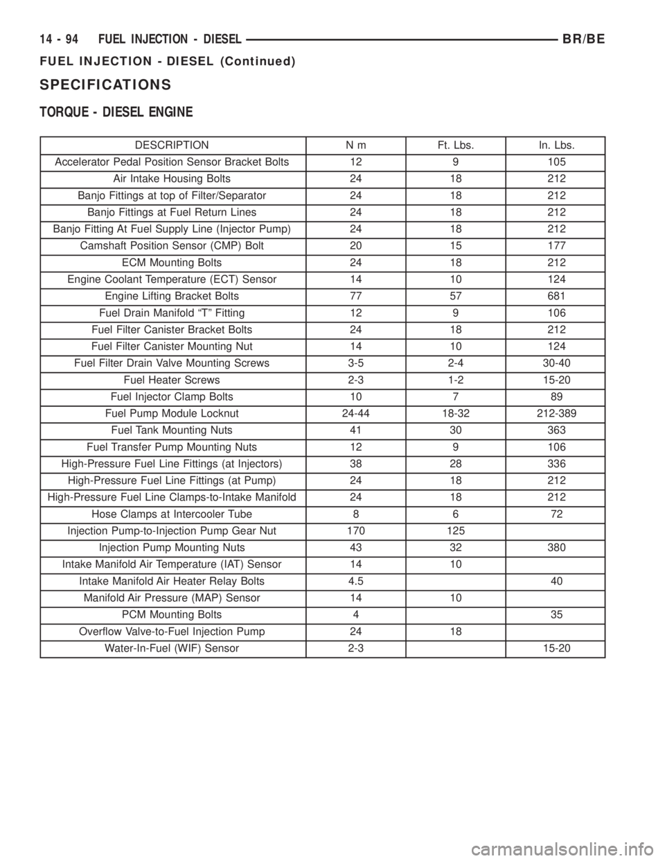
SPECIFICATIONS
TORQUE - DIESEL ENGINE
DESCRIPTION N m Ft. Lbs. In. Lbs.
Accelerator Pedal Position Sensor Bracket Bolts 12 9 105
Air Intake Housing Bolts 24 18 212
Banjo Fittings at top of Filter/Separator 24 18 212
Banjo Fittings at Fuel Return Lines 24 18 212
Banjo Fitting At Fuel Supply Line (Injector Pump) 24 18 212
Camshaft Position Sensor (CMP) Bolt 20 15 177
ECM Mounting Bolts 24 18 212
Engine Coolant Temperature (ECT) Sensor 14 10 124
Engine Lifting Bracket Bolts 77 57 681
Fuel Drain Manifold ªTº Fitting 12 9 106
Fuel Filter Canister Bracket Bolts 24 18 212
Fuel Filter Canister Mounting Nut 14 10 124
Fuel Filter Drain Valve Mounting Screws 3-5 2-4 30-40
Fuel Heater Screws 2-3 1-2 15-20
Fuel Injector Clamp Bolts 10 7 89
Fuel Pump Module Locknut 24-44 18-32 212-389
Fuel Tank Mounting Nuts 41 30 363
Fuel Transfer Pump Mounting Nuts 12 9 106
High-Pressure Fuel Line Fittings (at Injectors) 38 28 336
High-Pressure Fuel Line Fittings (at Pump) 24 18 212
High-Pressure Fuel Line Clamps-to-Intake Manifold 24 18 212
Hose Clamps at Intercooler Tube 8 6 72
Injection Pump-to-Injection Pump Gear Nut 170 125
Injection Pump Mounting Nuts 43 32 380
Intake Manifold Air Temperature (IAT) Sensor 14 10
Intake Manifold Air Heater Relay Bolts 4.5 40
Manifold Air Pressure (MAP) Sensor 14 10
PCM Mounting Bolts 4 35
Overflow Valve-to-Fuel Injection Pump 24 18
Water-In-Fuel (WIF) Sensor 2-3 15-20
14 - 94 FUEL INJECTION - DIESELBR/BE
FUEL INJECTION - DIESEL (Continued)
Page 1396 of 2255
(1) Disconnect both negative battery cables at both
batteries.
(2) Remove cable cover (Fig. 6). Cable cover is
attached with 2 Phillips screws, 2 plastic retention
clips and 2 push tabs (Fig. 6). Remove 2 Phillips
screws and carefully pry out 2 retention clips. After
clip removal, push rearward on front tab, and
upward on lower tab for cover removal.
(3) Using finger pressure only, disconnect end of
speed control servo cable from throttle lever pin by
pulling forward on connector while holding lever
rearward (Fig. 7).DO NOT try to pull connector
off perpendicular to lever pin. Connector will
be broken.
(4) Using two small screwdrivers, pry throttle
cable connector socket from throttle lever ball (Fig.
7).Be very careful not to bend throttle lever
arm.
(5) Disconnect transmission control cable at lever
arm (if equipped). Refer to 21, Transmission.
(6) Squeeze pinch tabs on speed control cable (Fig.
7) and pull cable rearward to remove from cable
mounting bracket.
(7) Squeeze pinch tabs on throttle cable (Fig. 7)
and pull cable rearward to remove from cable mount-
ing bracket.
(8) If equipped with an automatic transmission,
refer to 21, Transmission for transmission control
cable removal procedures.
(9) Disconnect wiring harness clip (Fig. 8) at bot-
tom of bracket.
(10) Remove 6 mounting bolts (Fig. 8) and par-
tially remove APPS assembly from engine. After
assembly is partially removed, disconnect electrical
connector from bottom of sensor by pushing on con-
nector tab (Fig. 9).
(11) Remove APPS assembly from engine.
INSTALLATION
The APPS is serviced (replaced) as one assembly
including the lever, brackets and sensor. The APPS is
calibrated to its mounting bracket. The APPS assem-
bly is located at left-front of engine below plastic
cable/lever/linkage cover (Fig. 6) .
(1) Snap electrical connector into bottom of sensor.
(2) Position APPS assembly to engine and install 6
bolts. Tighten bolts to 12 N´m (105 in. lbs.) torque.
(3) Connect wiring harness clip (Fig. 8) at bottom
of bracket.
(4) If equipped with an automatic transmission,
refer to Group 21, Transmission for transmission con-
trol cable installation procedures.
(5) Install speed control cable into mounting
bracket. Be sure pinch tabs (Fig. 7) have secured
cable.(6) Install throttle cable into mounting bracket. Be
sure pinch tabs (Fig. 7) have secured cable.
(7) Connect throttle cable at lever (snaps on).
(8) Connect speed control cable to lever by pushing
cable connector rearward onto lever pin while hold-
ing lever forward.
(9) Install cable cover.
(10) Connect both negative battery cables to both
batteries.
(11)ECM Calibration:Turn key to ON position.
Without starting engine, slowly press throttle pedal
to floor and then slowly release. This step must be
done (one time) to ensure accelerator pedal position
sensor calibration has been learned by ECM. If not
done, possible DTC's may be set.
(12) Use DRB scan tool to erase any DTC's from
ECM/PCM.
FUEL INJECTOR
DESCRIPTION
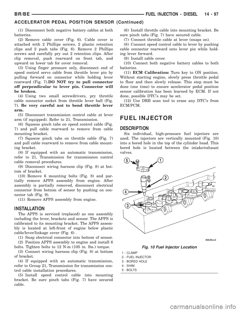
Six individual, high-pressure fuel injectors are
used. The injectors are vertically mounted (Fig. 10)
into a bored hole in the top of the cylinder head. This
bored hole is located between the intake/exhaust
valves.
Fig. 10 Fuel Injector Location
1 - CLAMP
2 - FUEL INJECTOR
3 - BORED HOLE
4 - SHIM
5 - BOLTS
BR/BEFUEL INJECTION - DIESEL 14 - 97
ACCELERATOR PEDAL POSITION SENSOR (Continued)
Page 1397 of 2255
OPERATION
High-pressure fuel is supplied from the injection
pump, through a high-pressure fuel line, through a
steel connector and into the fuel injector. When fuel
pressure rises to approximately 31,026 kPa (4,500
psi), the needle valve spring tension is overcome. The
needle valve rises and fuel flows through the spray
holes in the nozzle tip into the combustion chamber.
The pressure required to lift the needle valve is the
nozzle opening pressure. This is sometimes referred
to as the ªpopº pressure setting.
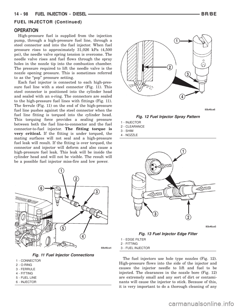
Each fuel injector is connected to each high-pres-
sure fuel line with a steel connector (Fig. 11). This
steel connector is positioned into the cylinder head
and sealed with an o-ring. The connectors are sealed
to the high-pressure fuel lines with fittings (Fig. 11).
The ferrule (Fig. 11) on the end of the high-pressure
fuel line pushes against the steel connector when the
fuel line fitting is torqued into the cylinder head.
This torquing force provides a sealing pressure
between both the fuel line-to-connector and the fuel
connector-to-fuel injector.The fitting torque is
very critical.If the fitting is under torqued, the
mating surfaces will not seal and a high-pressure
fuel leak will result. If the fitting is over torqued, the
connector and injector will deform and also cause a
high-pressure fuel leak. This leak will be inside the
cylinder head and will not be visible. The result will
be a possible fuel injector miss-fire and low power.
The fuel injectors use hole type nozzles (Fig. 12).
High-pressure flows into the side of the injector and
causes the injector needle to lift and fuel to be
injected. The clearances in the nozzle bore (Fig. 12)
are extremely small and any sort of dirt or contami-
nants will cause the injector to stick. Because of this,
it is very important to do a thorough cleaning of any
Fig. 11 Fuel Injector Connections
1 - CONNECTOR
2 - O-RING
3 - FERRULE
4 - FITTING
5 - FUEL LINE
6 - INJECTOR
Fig. 12 Fuel Injector Spray Pattern
1 - INJECTOR
2 - CLEARANCE
3 - SHIM
4 - NOZZLE
Fig. 13 Fuel Injector Edge Filter
1 - EDGE FILTER
2 - FITTING
3 - FUEL INJECTOR
14 - 98 FUEL INJECTION - DIESELBR/BE
FUEL INJECTOR (Continued)