2002 DODGE RAM lock
[x] Cancel search: lockPage 659 of 2255

connected to battery current from a fuse in the Junc-
tion Block (JB) through a fused ignition switch out-
put (run-acc) circuit.
²The coil ground terminal (85) is connected to the
relay control output of the CTM through the wiper
motor relay control circuit. The CTM controls the
ground path for this circuit internally to energize or
de-energize the wiper relay based upon its program-
ming and inputs from the wiper and washer control
circuitry of the multi-function switch and from the
wiper motor park switch.
²The coil battery terminal (86) is connected to
battery current from a fuse in the Junction Block
(JB) through a fused ignition switch output (run-acc)
circuit whenever the ignition switch is in the On or
Accessory positions.
²The normally open terminal (87) is connected to
battery current from a fuse in the Junction Block
(JB) through a fused ignition switch output (run-acc)
circuit whenever the wiper relay control coil is ener-
gized by the CTM. This circuit provides fused igni-
tion switch output (run-acc) current to the wiper
motor low speed brush only when the wiper relay
control coil is energized.
²The normally closed terminal (87A) is connected
to the output of the wiper motor park switch through
the wiper motor park switch sense circuit. This cir-
cuit provides battery current (wipers are not parked)
or ground (wipers are parked) to the wiper motor low
speed brush whenever the wiper relay control coil is
de-energized and the Off position of the wiper control
of the multi-function switch is selected.
The wiper relay can be diagnosed using conven-
tional diagnostic tools and methods.
DIAGNOSIS AND TESTING - WIPER RELAY
The wiper relay (or intermittent wipe relay) (Fig.
10) is located in the Power Distribution Center (PDC)
in the engine compartment. See the fuse and relay
layout label affixed to the inside surface of the PDC
cover for wiper relay identification and location.
Refer to the appropriate wiring information. The wir-
ing information includes wiring diagrams, proper
wire and connector repair procedures, details of wire
harness routing and retention, connector pin-out
information and location views for the various wire
harness connectors, splices and grounds.
(1) Remove the wiper relay from the PDC. (Refer
to 8 - ELECTRICAL/WIPERS/WASHERS/WIPER
RELAY - REMOVAL).
(2) A relay in the de-energized position should
have continuity between terminals 87A and 30, and
no continuity between terminals 87 and 30. If OK, go
to Step 3. If not OK, replace the faulty relay.(3) Resistance between terminals 85 and 86 (elec-
tromagnet) should be 75 5 ohms. If OK, go to Step
4. If not OK, replace the faulty relay.
(4) Connect a battery to terminals 85 and 86.
There should now be continuity between terminals
30 and 87, and no continuity between terminals 87A
and 30. If OK, test the relay input and output cir-
cuits. Refer to RELAY CIRCUIT TEST . If not OK,
replace the faulty relay.
RELAY CIRCUIT TEST
(1) The relay common feed terminal cavity (30) is
connected to the multi-function switch. There should
be continuity between the receptacle for terminal 30
of the wiper relay in the PDC and both driver low
speed wiper motor driver circuit cavities of the
instrument panel wire harness connector for the
multi-function switch at all times. If OK, go to Step
2. If not OK, repair the open driver low speed wiper
motor driver circuit(s) between the PDC and the
multi-function switch as required.
(2) The relay normally closed terminal (87A) is
connected to the wiper motor park switch through
the wiper motor park switch sense circuit. There
should be continuity between the receptacle for ter-
minal 87A of the wiper relay in the PDC and the
wiper motor park switch sense circuit cavity of the
headlamp and dash wire harness connector for the
wiper motor at all times. If OK, go to Step 3. If not
OK, repair the open wiper motor park switch sense
circuit between the PDC and the wiper motor as
required.
(3) The relay normally open terminal (87) is con-
nected to a fused ignition switch output (run-acc)
fuse in the Junction Block (JB) through a fused igni-
tion switch output (run-acc) circuit. There should be
battery voltage at the receptacle for terminal 87 of
Fig. 10 Wiper Relay
30 - COMMON FEED
85 - COIL GROUND
86 - COIL BATTERY
87 - NORMALLY OPEN
87A - NORMALLY CLOSED
8R - 16 WIPERS/WASHERSBR/BE
WIPER RELAY (Continued)
Page 662 of 2255

WIRING
TABLE OF CONTENTS
page page
AIRBAG SYSTEM.................... 8W-43-1
AIR CONDITIONING-HEATER........... 8W-42-1
ALL WHEEL ANTILOCK BRAKES........ 8W-35-1
AUDIO SYSTEM..................... 8W-47-1
BUS COMMUNICATIONS.............. 8W-18-1
CENTRAL TIMER MODULE............. 8W-45-1
CHARGING SYSTEM.................. 8W-20-1
COMPONENT INDEX.................. 8W-02-1
CONNECTOR/GROUND/SPLICE
LOCATION........................ 8W-91-1
CONNECTOR PIN-OUTS............... 8W-80-1
FRONT LIGHTING.................... 8W-50-1
FUEL/IGNITION SYSTEM.............. 8W-30-1
GROUND DISTRIBUTION.............. 8W-15-1
HORN/CIGAR LIGHTER/POWER OUTLET . . 8W-41-1
INSTRUMENT CLUSTER............... 8W-40-1
INTERIOR LIGHTING.................. 8W-44-1
JUNCTION BLOCK.................... 8W-12-1OVERHEAD CONSOLE................. 8W-49-1
POWER DISTRIBUTION............... 8W-10-1
POWER DISTRIBUTION............... 8W-97-1
POWER DOOR LOCKS................ 8W-61-1
POWER MIRRORS................... 8W-62-1
POWER SEATS...................... 8W-63-1
POWER WINDOWS................... 8W-60-1
REAR LIGHTING..................... 8W-51-1
REAR WHEEL ANTILOCK BRAKES....... 8W-34-1
SPLICE INFORMATION................ 8W-70-1
STARTING SYSTEM.................. 8W-21-1
TRAILER TOW....................... 8W-54-1
TRANSMISSION CONTROL SYSTEM..... 8W-31-1
TURN SIGNALS...................... 8W-52-1
VEHICLE SPEED CONTROL............ 8W-33-1
VEHICLE THEFT SECURITY SYSTEM..... 8W-39-1
WIPERS............................ 8W-53-1
WIRING DIAGRAM INFORMATION....... 8W-01-1 BR/BEWIRING 8W - 1
Page 671 of 2255
²Terminals in the wiring assembly are fully
seated into the connector/component and locked into
position
²Dirt or corrosion on the terminals. Any amount
of corrosion or dirt could cause an intermittent prob-
lem
²Damaged connector/component casing exposing
the item to dirt or moisture
²Wire insulation that has rubbed through causing
a short to ground
²Some or all of the wiring strands broken inside
of the insulation
²Wiring broken inside of the insulation
TROUBLESHOOTING WIRING PROBLEMS
When troubleshooting wiring problems there are
six steps which can aid in the procedure. The steps
are listed and explained below. Always check for non-
factory items added to the vehicle before doing any
diagnosis. If the vehicle is equipped with these items,
disconnect them to verify these add-on items are not
the cause of the problem.
(1) Verify the problem.
(2) Verify any related symptoms. Do this by per-
forming operational checks on components that are
in the same circuit. Refer to the wiring diagrams.
(3) Analyze the symptoms. Use the wiring dia-
grams to determine what the circuit is doing, where
the problem most likely is occurring and where the
diagnosis will continue.
(4) Isolate the problem area.
(5) Repair the problem area.
(6) Verify the proper operation. For this step,
check for proper operation of all items on the
repaired circuit. Refer to the wiring diagrams.
STANDARD PROCEDURE
STANDARD PROCEDURE - ELECTROSTATIC
DISCHARGE (ESD) SENSITIVE DEVICES
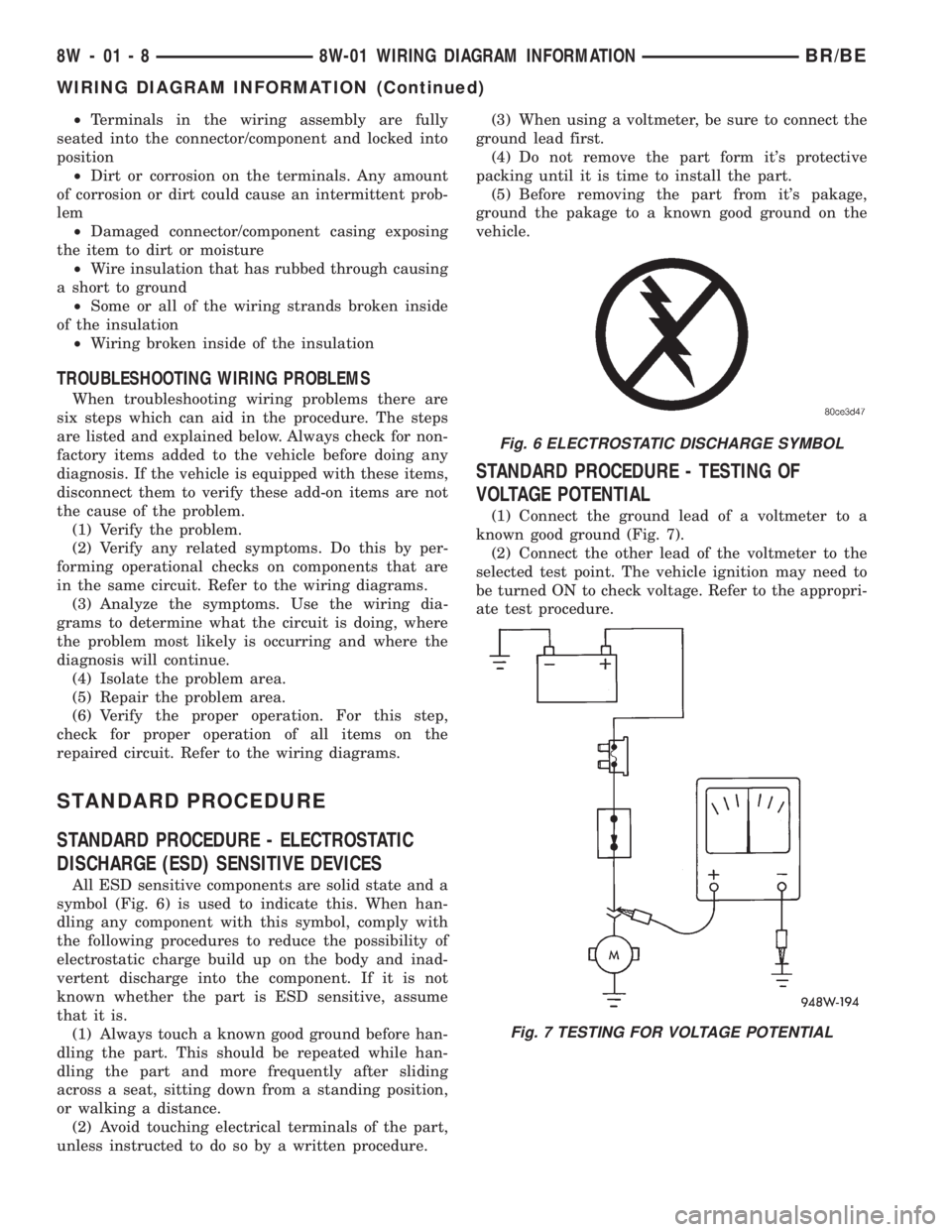
All ESD sensitive components are solid state and a
symbol (Fig. 6) is used to indicate this. When han-
dling any component with this symbol, comply with
the following procedures to reduce the possibility of
electrostatic charge build up on the body and inad-
vertent discharge into the component. If it is not
known whether the part is ESD sensitive, assume
that it is.
(1) Always touch a known good ground before han-
dling the part. This should be repeated while han-
dling the part and more frequently after sliding
across a seat, sitting down from a standing position,
or walking a distance.
(2) Avoid touching electrical terminals of the part,
unless instructed to do so by a written procedure.(3) When using a voltmeter, be sure to connect the
ground lead first.
(4) Do not remove the part form it's protective
packing until it is time to install the part.
(5) Before removing the part from it's pakage,
ground the pakage to a known good ground on the
vehicle.
STANDARD PROCEDURE - TESTING OF
VOLTAGE POTENTIAL
(1) Connect the ground lead of a voltmeter to a
known good ground (Fig. 7).
(2) Connect the other lead of the voltmeter to the
selected test point. The vehicle ignition may need to
be turned ON to check voltage. Refer to the appropri-
ate test procedure.
Fig. 6 ELECTROSTATIC DISCHARGE SYMBOL
Fig. 7 TESTING FOR VOLTAGE POTENTIAL
8W - 01 - 8 8W-01 WIRING DIAGRAM INFORMATIONBR/BE
WIRING DIAGRAM INFORMATION (Continued)
Page 672 of 2255
STANDARD PROCEDURE - TESTING FOR
CONTINUITY
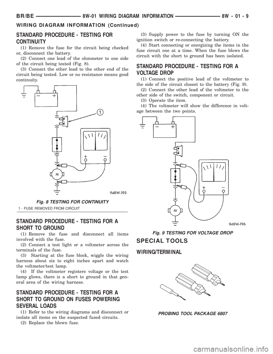
(1) Remove the fuse for the circuit being checked
or, disconnect the battery.
(2) Connect one lead of the ohmmeter to one side
of the circuit being tested (Fig. 8).
(3) Connect the other lead to the other end of the
circuit being tested. Low or no resistance means good
continuity.
STANDARD PROCEDURE - TESTING FOR A
SHORT TO GROUND
(1) Remove the fuse and disconnect all items
involved with the fuse.
(2) Connect a test light or a voltmeter across the
terminals of the fuse.
(3) Starting at the fuse block, wiggle the wiring
harness about six to eight inches apart and watch
the voltmeter/test lamp.
(4) If the voltmeter registers voltage or the test
lamp glows, there is a short to ground in that gen-
eral area of the wiring harness.
STANDARD PROCEDURE - TESTING FOR A
SHORT TO GROUND ON FUSES POWERING
SEVERAL LOADS
(1) Refer to the wiring diagrams and disconnect or
isolate all items on the suspected fused circuits.
(2) Replace the blown fuse.(3) Supply power to the fuse by turning ON the
ignition switch or re-connecting the battery.
(4) Start connecting or energizing the items in the
fuse circuit one at a time. When the fuse blows the
circuit with the short to ground has been isolated.
STANDARD PROCEDURE - TESTING FOR A
VOLTAGE DROP
(1) Connect the positive lead of the voltmeter to
the side of the circuit closest to the battery (Fig. 9).
(2) Connect the other lead of the voltmeter to the
other side of the switch, component or circuit.
(3) Operate the item.
(4) The voltmeter will show the difference in volt-
age between the two points.
SPECIAL TOOLS
WIRING/TERMINAL
Fig. 8 TESTING FOR CONTINUITY
1 - FUSE REMOVED FROM CIRCUIT
Fig. 9 TESTING FOR VOLTAGE DROP
PROBING TOOL PACKAGE 6807
BR/BE8W-01 WIRING DIAGRAM INFORMATION 8W - 01 - 9
WIRING DIAGRAM INFORMATION (Continued)
Page 673 of 2255
CONNECTOR
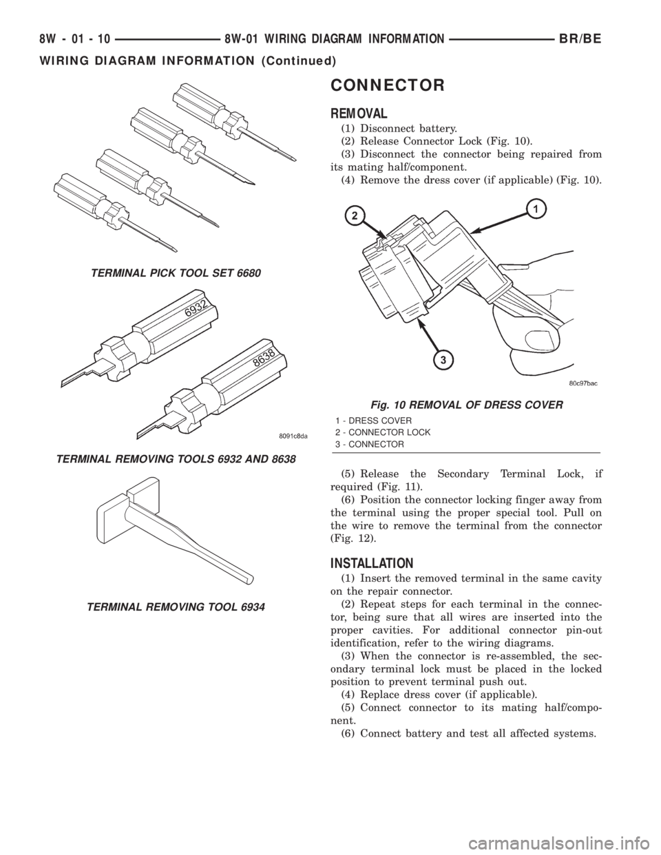
REMOVAL
(1) Disconnect battery.
(2) Release Connector Lock (Fig. 10).
(3) Disconnect the connector being repaired from
its mating half/component.
(4) Remove the dress cover (if applicable) (Fig. 10).
(5) Release the Secondary Terminal Lock, if
required (Fig. 11).
(6) Position the connector locking finger away from
the terminal using the proper special tool. Pull on
the wire to remove the terminal from the connector
(Fig. 12).
INSTALLATION
(1) Insert the removed terminal in the same cavity
on the repair connector.
(2) Repeat steps for each terminal in the connec-
tor, being sure that all wires are inserted into the
proper cavities. For additional connector pin-out
identification, refer to the wiring diagrams.
(3) When the connector is re-assembled, the sec-
ondary terminal lock must be placed in the locked
position to prevent terminal push out.
(4) Replace dress cover (if applicable).
(5) Connect connector to its mating half/compo-
nent.
(6) Connect battery and test all affected systems.
TERMINAL PICK TOOL SET 6680
TERMINAL REMOVING TOOLS 6932 AND 8638
TERMINAL REMOVING TOOL 6934
Fig. 10 REMOVAL OF DRESS COVER
1 - DRESS COVER
2 - CONNECTOR LOCK
3 - CONNECTOR
8W - 01 - 10 8W-01 WIRING DIAGRAM INFORMATIONBR/BE
WIRING DIAGRAM INFORMATION (Continued)
Page 674 of 2255
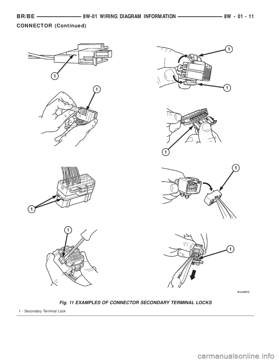
Fig. 11 EXAMPLES OF CONNECTOR SECONDARY TERMINAL LOCKS
1 - Secondary Terminal Lock
BR/BE8W-01 WIRING DIAGRAM INFORMATION 8W - 01 - 11
CONNECTOR (Continued)
Page 676 of 2255
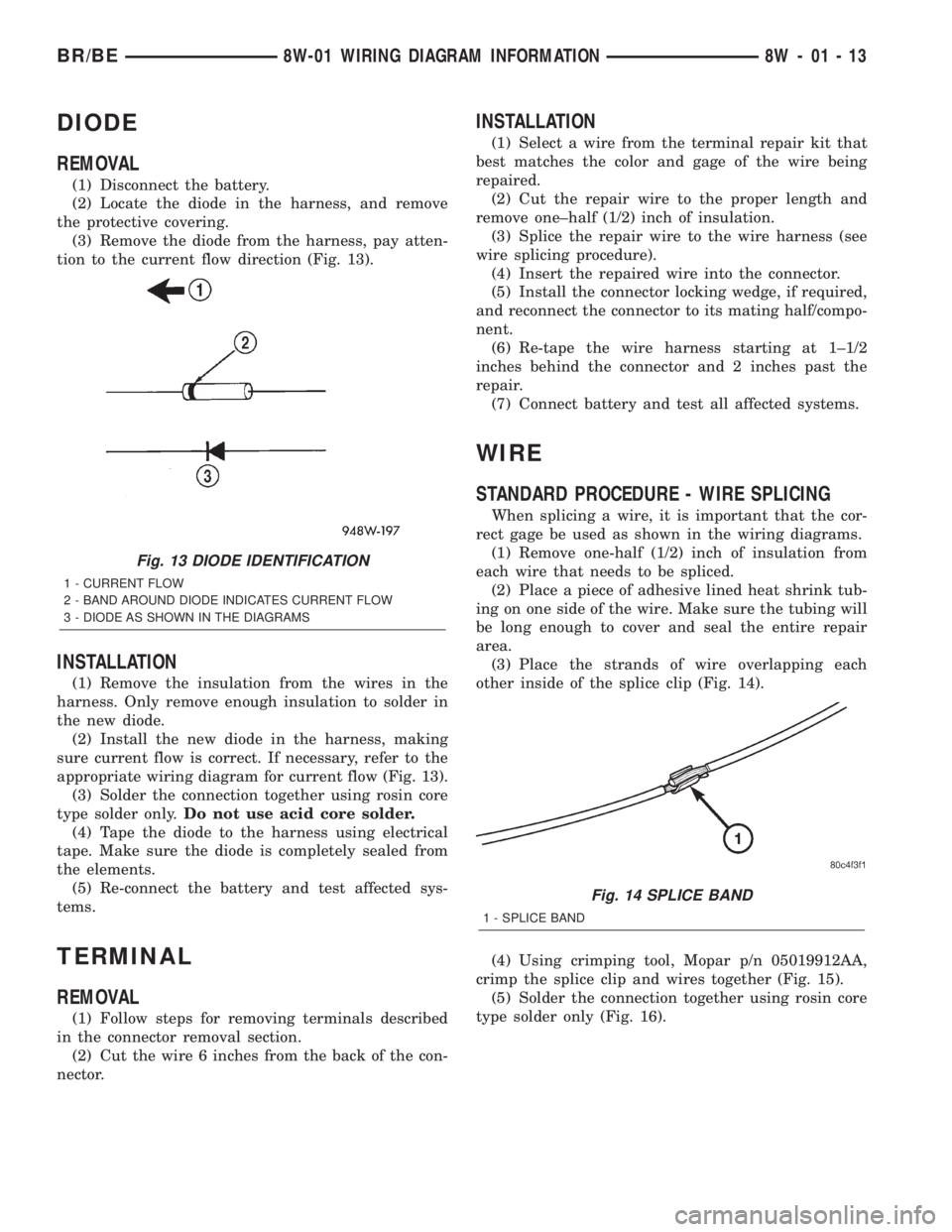
DIODE
REMOVAL
(1) Disconnect the battery.
(2) Locate the diode in the harness, and remove
the protective covering.
(3) Remove the diode from the harness, pay atten-
tion to the current flow direction (Fig. 13).
INSTALLATION
(1) Remove the insulation from the wires in the
harness. Only remove enough insulation to solder in
the new diode.
(2) Install the new diode in the harness, making
sure current flow is correct. If necessary, refer to the
appropriate wiring diagram for current flow (Fig. 13).
(3) Solder the connection together using rosin core
type solder only.Do not use acid core solder.
(4) Tape the diode to the harness using electrical
tape. Make sure the diode is completely sealed from
the elements.
(5) Re-connect the battery and test affected sys-
tems.
TERMINAL
REMOVAL
(1) Follow steps for removing terminals described
in the connector removal section.
(2) Cut the wire 6 inches from the back of the con-
nector.
INSTALLATION
(1) Select a wire from the terminal repair kit that
best matches the color and gage of the wire being
repaired.
(2) Cut the repair wire to the proper length and
remove one±half (1/2) inch of insulation.
(3) Splice the repair wire to the wire harness (see
wire splicing procedure).
(4) Insert the repaired wire into the connector.
(5) Install the connector locking wedge, if required,
and reconnect the connector to its mating half/compo-
nent.
(6) Re-tape the wire harness starting at 1±1/2
inches behind the connector and 2 inches past the
repair.
(7) Connect battery and test all affected systems.
WIRE
STANDARD PROCEDURE - WIRE SPLICING
When splicing a wire, it is important that the cor-
rect gage be used as shown in the wiring diagrams.
(1) Remove one-half (1/2) inch of insulation from
each wire that needs to be spliced.
(2) Place a piece of adhesive lined heat shrink tub-
ing on one side of the wire. Make sure the tubing will
be long enough to cover and seal the entire repair
area.
(3) Place the strands of wire overlapping each
other inside of the splice clip (Fig. 14).
(4) Using crimping tool, Mopar p/n 05019912AA,
crimp the splice clip and wires together (Fig. 15).
(5) Solder the connection together using rosin core
type solder only (Fig. 16).
Fig. 13 DIODE IDENTIFICATION
1 - CURRENT FLOW
2 - BAND AROUND DIODE INDICATES CURRENT FLOW
3 - DIODE AS SHOWN IN THE DIAGRAMS
Fig. 14 SPLICE BAND
1 - SPLICE BAND
BR/BE8W-01 WIRING DIAGRAM INFORMATION 8W - 01 - 13
Page 678 of 2255

8W-02 COMPONENT INDEX
Component Page
4WD Switch.......................... 8W-31
A/C Compressor Clutch Relay............ 8W-42
A/C Compressor Clutch................. 8W-42
A/C- Heater Control.................... 8W-42
A/C Heater Temperature Select........... 8W-42
A/C High Pressure Switch............... 8W-42
A/C Low Pressure Switch................ 8W-42
Accelerator Pedal Position Sensor......... 8W-30
Aftermarket Center High Mounted Stop
Lamp............................. 8W-51
Aftermarket Trailer Tow Connector........ 8W-54
Airbag Control Module.................. 8W-43
Ambient Temperature Sensor............ 8W-49
Ash Receiver Lamp.................... 8W-44
Automatic Day/Night Mirror............. 8W-49
Automatic Shut Down Relay............. 8W-30
Auxiliary Battery...................... 8W-20
Back-Up Lamp Switch.................. 8W-51
Back-Up Lamp........................ 8W-51
Battery Temperature Sensor............. 8W-30
Battery............................. 8W-20
Blend Door Actuator................... 8W-42
Blower Motor Relay.................... 8W-42
Blower Motor Resistor Block............. 8W-42
Blower Motor......................... 8W-42
Brake Lamp Switch.................... 8W-51
Brake Pressure Switch............... 8W-34, 35
Bypass Jumper....................... 8W-21
Camshaft Position Sensor............... 8W-30
Capacitor......................... 8W-10, 30
Cargo Lamps........................ 8W-44
Center High Mounted Stop Lamps........ 8W-51
Center Identification Lamp.............. 8W-50
Central Timer Module.................. 8W-45
Cigar Lighter......................... 8W-41
Circuit Breakers...................... 8W-12
Clockspring.................. 8W-33, 41, 43, 47
Clutch Pedal Position Switch............. 8W-21
Combination Flasher................... 8W-52
Controller Antilock Brake............ 8W-34, 35
Crankshaft Position Sensor.............. 8W-30
Cummins Bus........................ 8W-18
Cup Holder Lamp..................... 8W-44
Data Link Connector................... 8W-18
Daytime Running Lamp Module.......... 8W-50
Dome Lamp.......................... 8W-44
Driver Airbag......................... 8W-43
Driver Cylinder Lock Switch............. 8W-39
Driver Door Ajar Switch................ 8W-45
Driver Door Lock Motor................. 8W-61
Driver Door Window/Lock Switch...... 8W-60, 61
Driver Heated Seat Cushion............. 8W-63Component Page
Driver Heated Seat Switch.............. 8W-63
Driver Lumbar Motor.................. 8W-63
Driver Power Seat Front Vertical Motor.... 8W-63
Driver Power Seat Horizontal Motor....... 8W-63
Driver Power Seat Rear Vertical Motor..... 8W-63
Driver Power Seat Switch............... 8W-63
Driver Power Window Motor............. 8W-60
Electric Brake Provision................ 8W-54
Engine Control Module................. 8W-30
Engine Coolant Temperature Sensor....... 8W-30
Engine Oil Pressure Sensor.............. 8W-30
Engine Starter Motor Relay.............. 8W-21
Engine Starter Motor................... 8W-21
EVAP/Purge Solenoid................... 8W-30
Fender Lamp......................... 8W-51
Fog Lamp Relay....................... 8W-50
Fog Lamp............................ 8W-50
Fuel Heater Relay..................... 8W-30
Fuel Heater........................ 8W-30-36
Fuel Injection Pump................... 8W-30
Fuel Injectors......................... 8W-30
Fuel Pump Module.................... 8W-30
Fuel Pump Relay...................... 8W-30
Fuel Tank Module..................... 8W-30
Fuel Transfer Pump.................... 8W-30
Fuses (JB)........................... 8W-12
Fuses (PDC).......................... 8W-10
Fusible Link....................... 8W-20, 30
Grounds............................. 8W-15
Generator............................ 8W-20
Glove Box Lamp And Switch............. 8W-44
Headlamp Beam Select Switch........... 8W-50
Headlamp Switch...................... 8W-50
Headlamp........................... 8W-50
Heated Mirror Relay................... 8W-62
Heated Mirror Switch.................. 8W-62
Heated Seat Relay..................... 8W-12
High Note Horn....................... 8W-41
Horn Relay.......................... 8W-41
Horn Switch.......................... 8W-41
Idle Air Control Motor.................. 8W-30
Ignition Coils......................... 8W-30
Ignition Switch....................... 8W-10
Instrument Cluster.................... 8W-40
Intake Air Heater Relays................ 8W-30
Intake Air Heater..................... 8W-30
Intake Air Temperature Sensor........... 8W-30
Intermittent Wiper Switch............... 8W-53
Joint Connectors....... 8W-10, 12, 15, 30, 34, 35,
40, 44, 45, 51, 53, 54, 70
Junction Block........................ 8W-12
Leak Detection Pump.................. 8W-30
BR/BE8W-02 COMPONENT INDEX 8W - 02 - 1