2002 DODGE RAM lock
[x] Cancel search: lockPage 608 of 2255
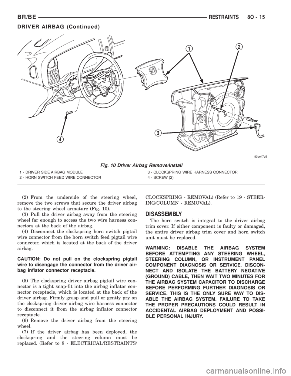
(2) From the underside of the steering wheel,
remove the two screws that secure the driver airbag
to the steering wheel armature (Fig. 10).
(3) Pull the driver airbag away from the steering
wheel far enough to access the two wire harness con-
nectors at the back of the airbag.
(4) Disconnect the clockspring horn switch pigtail
wire connector from the horn switch feed pigtail wire
connector, which is located at the back of the driver
airbag.
CAUTION: Do not pull on the clockspring pigtail
wire to disengage the connector from the driver air-
bag inflator connector receptacle.
(5) The clockspring driver airbag pigtail wire con-
nector is a tight snap-fit into the airbag inflator con-
nector receptacle, which is located at the back of the
driver airbag. Firmly grasp and pull or gently pry on
the clockspring driver airbag wire harness connector
to disconnect it from the airbag inflator connector
receptacle.
(6) Remove the driver airbag from the steering
wheel.
(7) If the driver airbag has been deployed, the
clockspring and the steering column must be
replaced. (Refer to 8 - ELECTRICAL/RESTRAINTS/CLOCKSPRING - REMOVAL) (Refer to 19 - STEER-
ING/COLUMN - REMOVAL).
DISASSEMBLY
The horn switch is integral to the driver airbag
trim cover. If either component is faulty or damaged,
the entire driver airbag trim cover and horn switch
unit must be replaced.
WARNING: DISABLE THE AIRBAG SYSTEM
BEFORE ATTEMPTING ANY STEERING WHEEL,
STEERING COLUMN, OR INSTRUMENT PANEL
COMPONENT DIAGNOSIS OR SERVICE. DISCON-
NECT AND ISOLATE THE BATTERY NEGATIVE
(GROUND) CABLE, THEN WAIT TWO MINUTES FOR
THE AIRBAG SYSTEM CAPACITOR TO DISCHARGE
BEFORE PERFORMING FURTHER DIAGNOSIS OR
SERVICE. THIS IS THE ONLY SURE WAY TO DIS-
ABLE THE AIRBAG SYSTEM. FAILURE TO TAKE
THE PROPER PRECAUTIONS COULD RESULT IN
ACCIDENTAL AIRBAG DEPLOYMENT AND POSSI-
BLE PERSONAL INJURY.
Fig. 10 Driver Airbag Remove/Install
1 - DRIVER SIDE AIRBAG MODULE
2 - HORN SWITCH FEED WIRE CONNECTOR3 - CLOCKSPRING WIRE HARNESS CONNECTOR
4 - SCREW (2)
BR/BERESTRAINTS 8O - 15
DRIVER AIRBAG (Continued)
Page 609 of 2255
WARNING: THE HORN SWITCH IS INTEGRAL TO
THE DRIVER AIRBAG UNIT. SERVICE OF THIS UNIT
SHOULD BE PERFORMED ONLY BY
DAIMLERCHRYSLER-TRAINED AND AUTHORIZED
DEALER SERVICE TECHNICIANS. FAILURE TO
TAKE THE PROPER PRECAUTIONS OR TO FOL-
LOW THE PROPER PROCEDURES COULD RESULT
IN ACCIDENTAL, INCOMPLETE, OR IMPROPER AIR-
BAG DEPLOYMENT AND POSSIBLE OCCUPANT
INJURIES.
(1) Disconnect and isolate the battery negative
cable. If either of the airbags has not been deployed,
wait two minutes for the system capacitor to dis-
charge before further service.
(2) Remove the driver airbag from the steering
wheel. (Refer to 8 - ELECTRICAL/RESTRAINTS/
DRIVER AIRBAG - REMOVAL).
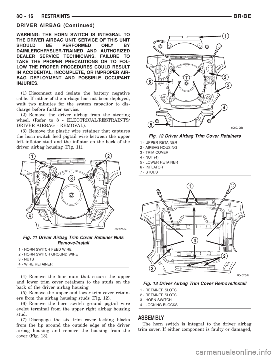
(3) Remove the plastic wire retainer that captures
the horn switch feed pigtail wire between the upper
left inflator stud and the inflator on the back of the
driver airbag housing (Fig. 11).
(4) Remove the four nuts that secure the upper
and lower trim cover retainers to the studs on the
back of the driver airbag housing
(5) Remove the upper and lower trim cover retain-
ers from the airbag housing studs (Fig. 12).
(6) Remove the horn switch ground pigtail wire
eyelet terminal from the upper right airbag housing
stud.
(7) Disengage the six trim cover locking blocks
from the lip around the outside edge of the driver
airbag housing and remove the housing from the
cover (Fig. 13).
ASSEMBLY
The horn switch is integral to the driver airbag
trim cover. If either component is faulty or damaged,
Fig. 11 Driver Airbag Trim Cover Retainer Nuts
Remove/Install
1 - HORN SWITCH FEED WIRE
2 - HORN SWITCH GROUND WIRE
3 - NUTS
4 - WIRE RETAINER
Fig. 12 Driver Airbag Trim Cover Retainers
1 - UPPER RETAINER
2 - AIRBAG HOUSING
3 - TRIM COVER
4 - NUT (4)
5 - LOWER RETAINER
6 - INFLATOR
7 - STUDS
Fig. 13 Driver Airbag Trim Cover Remove/Install
1 - RETAINER SLOTS
2 - RETAINER SLOTS
3 - HORN SWITCH
4 - LOCKING BLOCKS
8O - 16 RESTRAINTSBR/BE
DRIVER AIRBAG (Continued)
Page 610 of 2255
the entire driver airbag trim cover and horn switch
unit must be replaced.
WARNING: DISABLE THE AIRBAG SYSTEM
BEFORE ATTEMPTING ANY STEERING WHEEL,
STEERING COLUMN, OR INSTRUMENT PANEL
COMPONENT DIAGNOSIS OR SERVICE. DISCON-
NECT AND ISOLATE THE BATTERY NEGATIVE
(GROUND) CABLE, THEN WAIT TWO MINUTES FOR
THE AIRBAG SYSTEM CAPACITOR TO DISCHARGE
BEFORE PERFORMING FURTHER DIAGNOSIS OR
SERVICE. THIS IS THE ONLY SURE WAY TO DIS-
ABLE THE AIRBAG SYSTEM. FAILURE TO TAKE
THE PROPER PRECAUTIONS COULD RESULT IN
ACCIDENTAL AIRBAG DEPLOYMENT AND POSSI-
BLE PERSONAL INJURY.
WARNING: THE HORN SWITCH IS INTEGRAL TO
THE DRIVER AIRBAG UNIT. SERVICE OF THIS UNIT
SHOULD BE PERFORMED ONLY BY
DAIMLERCHRYSLER-TRAINED AND AUTHORIZED
DEALER SERVICE TECHNICIANS. FAILURE TO
TAKE THE PROPER PRECAUTIONS OR TO FOL-
LOW THE PROPER PROCEDURES COULD RESULT
IN ACCIDENTAL, INCOMPLETE, OR IMPROPER AIR-
BAG DEPLOYMENT AND POSSIBLE OCCUPANT
INJURIES.
WARNING: USE EXTREME CARE TO PREVENT ANY
FOREIGN MATERIAL FROM ENTERING THE DRIVER
AIRBAG, OR BECOMING ENTRAPPED BETWEEN
THE DRIVER AIRBAG CUSHION AND THE DRIVER
AIRBAG TRIM COVER. FAILURE TO OBSERVE THIS
WARNING COULD RESULT IN OCCUPANT INJURIES
UPON AIRBAG DEPLOYMENT.
WARNING: THE DRIVER AIRBAG TRIM COVER
MUST NEVER BE PAINTED. REPLACEMENT TRIM
COVERS ARE SERVICED IN THE ORIGINAL COL-
ORS. PAINT MAY CHANGE THE WAY IN WHICH THE
MATERIAL OF THE TRIM COVER RESPONDS TO AN
AIRBAG DEPLOYMENT. FAILURE TO OBSERVE
THIS WARNING COULD RESULT IN OCCUPANT
INJURIES UPON AIRBAG DEPLOYMENT.
(1) Carefully position the driver airbag in the trim
cover. Be certain that the horn switch feed and
ground pigtail wires are not pinched between the air-
bag housing and the trim cover locking blocks.
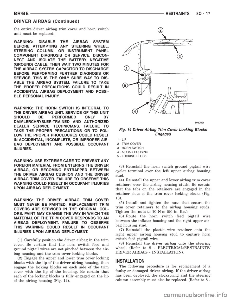
(2) Engage the upper and lower trim cover locking
blocks with the lip of the driver airbag housing, then
engage the locking blocks on each side of the trim
cover with the lip of the housing. Be certain that
each of the locking blocks is fully engaged on the lip
of the airbag housing (Fig. 14).(3) Reinstall the horn switch ground pigtail wire
eyelet terminal over the left upper airbag housing
stud.
(4) Reinstall the upper and lower airbag trim cover
retainers over the airbag housing studs. Be certain
that the tabs on the retainers are engaged in the
retainer slots of the trim cover locking blocks (Fig.
13).
(5) Install and tighten the nuts that secure the
trim cover retainers to the airbag housing studs.
Tighten the nuts to 10 N´m (90 in. lbs.).
(6) Route the horn switch feed pigtail wire
between the inflator housing and the right upper air-
bag housing stud.
(7) Reinstall the plastic wire retainer onto the
right upper airbag housing stud to capture horn
switch feed pigtail wire.
(8) Reinstall the driver airbag onto the steering
wheel. (Refer to 8 - ELECTRICAL/RESTRAINTS/
DRIVER AIRBAG - INSTALLATION).
INSTALLATION
The following procedure is for replacement of a
faulty or damaged driver airbag. If the driver airbag
has been deployed, the clockspring and the steering
column assembly must also be replaced. (Refer to 8 -
Fig. 14 Driver Airbag Trim Cover Locking Blocks
Engaged
1 - LIP
2 - TRIM COVER
3 - HORN SWITCH
4 - AIRBAG HOUSING
5 - LOCKING BLOCK
BR/BERESTRAINTS 8O - 17
DRIVER AIRBAG (Continued)
Page 611 of 2255

ELECTRICAL/RESTRAINTS/CLOCKSPRING -
REMOVAL) and (Refer to 19 - STEERING/COLUMN
- REMOVAL).
WARNING: DISABLE THE AIRBAG SYSTEM
BEFORE ATTEMPTING ANY STEERING WHEEL,
STEERING COLUMN, OR INSTRUMENT PANEL
COMPONENT DIAGNOSIS OR SERVICE. DISCON-
NECT AND ISOLATE THE BATTERY NEGATIVE
(GROUND) CABLE, THEN WAIT TWO MINUTES FOR
THE AIRBAG SYSTEM CAPACITOR TO DISCHARGE
BEFORE PERFORMING FURTHER DIAGNOSIS OR
SERVICE. THIS IS THE ONLY SURE WAY TO DIS-
ABLE THE AIRBAG SYSTEM. FAILURE TO TAKE
THE PROPER PRECAUTIONS COULD RESULT IN
ACCIDENTAL AIRBAG DEPLOYMENT AND POSSI-
BLE PERSONAL INJURY.
WARNING: USE EXTREME CARE TO PREVENT ANY
FOREIGN MATERIAL FROM ENTERING THE DRIVER
AIRBAG, OR BECOMING ENTRAPPED BETWEEN
THE DRIVER AIRBAG CUSHION AND THE DRIVER
AIRBAG TRIM COVER. FAILURE TO OBSERVE THIS
WARNING COULD RESULT IN OCCUPANT INJURIES
UPON AIRBAG DEPLOYMENT.
WARNING: THE DRIVER AIRBAG TRIM COVER
MUST NEVER BE PAINTED. REPLACEMENT TRIM
COVERS ARE SERVICED IN THE ORIGINAL COL-
ORS. PAINT MAY CHANGE THE WAY IN WHICH THE
MATERIAL OF THE TRIM COVER RESPONDS TO AN
AIRBAG DEPLOYMENT. FAILURE TO OBSERVE
THIS WARNING COULD RESULT IN OCCUPANT
INJURIES UPON AIRBAG DEPLOYMENT.
(1) Assemble the driver airbag trim cover onto the
airbag housing. (Refer to 8 - ELECTRICAL/RE-
STRAINTS/DRIVER AIRBAG - ASSEMBLY).
(2) When installing the driver airbag, reconnect
the clockspring driver airbag pigtail wire harness
connector to the airbag inflator connector receptacle
by pressing straight in on the connector (Fig. 10). You
can be certain that the connector is fully engaged by
listening carefully for a distinct, audible click as the
connector snaps into place.
(3) Reconnect the clockspring horn switch pigtail
wire harness connector to the horn switch feed pig-
tail wire connector, which is located on the back of
the driver airbag.
(4) Carefully position the driver airbag in the
steering wheel. Be certain that the clockspring pig-
tail wires in the steering wheel hub area are not
pinched between the driver airbag and the steering
wheel.(5) From the underside of the steering wheel,
install and tighten the two screws that secure the
driver airbag to the steering wheel armature.
Tighten the screws to 10.2 N´m (90 in. lbs.).
(6) Do not reconnect the battery negative cable at
this time. The airbag system verification test proce-
dure should be performed following service of any
airbag system component. (Refer to 8 - ELECTRI-
CAL/RESTRAINTS - STANDARD PROCEDURE -
VERIFICATION TEST).
FRONT SEAT BELT &
RETRACTOR
REMOVAL
REMOVAL - STANDARD CAB
WARNING: DURING AND FOLLOWING ANY SEAT
BELT SERVICE, CAREFULLY INSPECT ALL SEAT
BELTS, BUCKLES, MOUNTING HARDWARE, AND
RETRACTORS FOR PROPER INSTALLATION,
OPERATION, OR DAMAGE. REPLACE ANY BELT
THAT IS CUT, FRAYED, OR TORN. STRAIGHTEN
ANY BELT THAT IS TWISTED. TIGHTEN ANY
LOOSE FASTENERS. REPLACE ANY BELT THAT
HAS A DAMAGED OR INOPERATIVE BUCKLE OR
RETRACTOR. REPLACE ANY BELT THAT HAS A
BENT OR DAMAGED LATCH PLATE OR ANCHOR
PLATE. NEVER ATTEMPT TO REPAIR A SEAT BELT
COMPONENT. ALWAYS REPLACE DAMAGED OR
FAULTY SEAT BELT COMPONENTS WITH THE COR-
RECT, NEW AND UNUSED REPLACEMENT PARTS
LISTED IN THE MOPAR PARTS CATALOG.
(1) Move the front seats to their most forward
position for easiest access to the front shoulder belt
lower seat belt anchor plate, the retractor, and the
B-pillar.
(2) Remove the screw that secures the lower seat
belt anchor plate to the floor panel near the base of
the B-pillar.
(3) Unsnap and lift the front shoulder belt turning
loop cover to access the screw that secures the turn-
ing loop to the height adjuster (Fig. 15).
(4) Remove the screw that secures the shoulder
belt turning loop to the height adjuster.
(5) Remove the shoulder belt turning loop from the
height adjuster.
(6) Remove the trim from the B-pillar. (Refer to 23
- BODY/INTERIOR/B-PILLAR TRIM - REMOVAL).
(7) Disengage the front seat shoulder belt turning
loop and lower seat belt anchor plate from the B-pil-
lar trim.
8O - 18 RESTRAINTSBR/BE
DRIVER AIRBAG (Continued)
Page 617 of 2255
switch is in its installed position, the only compo-
nents visible through the dedicated opening of the
cluster bezel are the switch face plate and nomencla-
ture, the key cylinder actuator, and a small round
lens with the text9Off9imprinted on it. The ªOnº
position of the switch is designated by text imprinted
upon the face plate of the switch, but is not illumi-
nated. The remainder of the switch is concealed
behind the switch face plate and the instrument
panel cluster bezel.
The passenger airbag on-off switch housing is con-
structed of molded plastic and has three integral
mounting tabs. These mounting tabs are used to
secure the switch to the back of the molded plastic
switch face plate with three small screws. The
molded plastic face plate also has three integral
mounting tabs that are used to secure the switch and
face plate unit to the instrument panel carrier with
three additional screws. Two short pigtail wires with
molded plastic connector insulators exit the back of
the switch housing and connect the switch to the
vehicle electrical system through two dedicated take
outs of the instrument panel wire harness. The har-
ness take outs are equipped with molded plastic con-
nector insulators that are keyed and latched to
ensure proper and secure switch electrical connec-
tions. The passenger airbag on/off switch cannot be
adjusted or repaired and, if faulty or damaged, the
switch must be replaced.
OPERATION
The passenger airbag on/off switch allows the cus-
tomer to turn the passenger airbag function On or
Off to accommodate certain uses of the right front
seating position where airbag protection may not be
desired. See the owner's manual in the vehicle glove
box for specific recommendations on when to enable
or disable the passenger airbag. The Off indicator of
the switch will be illuminated whenever the switch is
turned to the Off position. The ignition key is the
only key or object that should ever be inserted into
the switch. The on/off switch requires only a partial
key insertion to fully depress a spring-loaded locking
plunger. The spring-loaded locking plunger prevents
the user from leaving the key in the switch. The key
will be automatically ejected when force is not
applied. To actuate the passenger side airbag on/off
switch, insert the ignition key into the switch key
actuator far enough to fully depress the plunger and
rotate to the desired switch position. When the
switch key actuator is rotated to its clockwise stop
(the key actuator slot will be aligned with the Off
indicator lamp), the Off indicator is illuminated and
the passenger airbag is disabled. When the switch is
rotated to its counterclockwise stop (the key actuator
slot will be in a vertical position), the Off indicatorwill be extinguished and the passenger airbag is
enabled.
The passenger airbag on/off switch is connected in
series between the Airbag Control Module (ACM) and
the passenger airbag inflator unit. When the switch
is in the On position, the switch connects the ACM
directly to the passenger airbag inflator. When the
switch is in the Off position it interrupts the inflator
circuits, but replaces the normal resistance in these
circuits with an internal resistor. Thus, the ACM is
unable to distinguish the mode of the switch and still
sends an electrical signal as though it were deploying
the passenger airbag when it detects a sufficient
impact. However, the switch position should not be
changed while the ignition switch is in the On posi-
tion, as the ACM may detect a fault, record a Diag-
nostic Trouble Code (DTC), and illuminate the Airbag
indicator in response to a momentary open it senses
in the passenger airbag inflator circuits as the on/off
switch changes states.
REMOVAL
WARNING: DISABLE THE AIRBAG SYSTEM
BEFORE ATTEMPTING ANY STEERING WHEEL,
STEERING COLUMN, OR INSTRUMENT PANEL
COMPONENT DIAGNOSIS OR SERVICE. DISCON-
NECT AND ISOLATE THE BATTERY NEGATIVE
(GROUND) CABLE, THEN WAIT TWO MINUTES FOR
THE AIRBAG SYSTEM CAPACITOR TO DISCHARGE
BEFORE PERFORMING FURTHER DIAGNOSIS OR
SERVICE. THIS IS THE ONLY SURE WAY TO DIS-
ABLE THE AIRBAG SYSTEM. FAILURE TO TAKE
THE PROPER PRECAUTIONS COULD RESULT IN
ACCIDENTAL AIRBAG DEPLOYMENT AND POSSI-
BLE PERSONAL INJURY.
(1) Disconnect and isolate the battery negative
cable. If either of the airbags has not been deployed,
wait two minutes for the system capacitor to dis-
charge before further service.
(2) Remove the cluster bezel from the instrument
panel. (Refer to 23 - BODY/INSTRUMENT PANEL/
CLUSTER BEZEL - REMOVAL).
(3) Remove the glove box from the instrument
panel. (Refer to 23 - BODY/INSTRUMENT PANEL/
GLOVE BOX - REMOVAL).
(4) Reach through the glove box opening to access
and disconnect the two passenger airbag on/off
switch pigtail wire harness connectors from the
instrument panel wire harness connectors. These
connectors are retained on a bracket located on the
inboard glove box opening reinforcement (Fig. 20).
(5) Remove the three screws that secure the pas-
senger airbag on/off switch face plate to the instru-
ment panel (Fig. 21).
8O - 24 RESTRAINTSBR/BE
PASSENGER AIRBAG ON/OFF SWITCH (Continued)
Page 625 of 2255

DESCRIPTION - VEHICLE SPEED INPUT
Gas Engines and/or Diesel With Automatic Trans.
The Vehicle Speed Sensor (VSS) is no longer used
for any Dodge Truck.
Vehicle speed and distance covered are measured
by the Rear Wheel Speed Sensor. The sensor is
mounted to the rear axle. A signal is sent from this
sensor to the Controller Antilock Brake (CAB) com-
puter. A signal is then sent from the CAB to the Pow-
ertrain Control Module (PCM) to determine vehicle
speed and distance covered. The PCM will then
determine strategies for speed control system opera-
tion.
Diesel With Manual Trans.
The Vehicle Speed Sensor (VSS) is no longer used
for any Dodge Truck.
Vehicle speed and distance covered are measured
by the Rear Wheel Speed Sensor. The sensor is
mounted to the rear axle. A signal is sent from this
sensor to the Controller Antilock Brake (CAB) com-
puter. A signal is then sent from the CAB to the
Engine Control Module (ECM) to determine vehicle
speed and distance covered. The ECM will then
determine strategies for speed control system opera-
tion.
OPERATION - SPEED CONTROL SYSTEM
Gas Engines and/or Diesel With Automatic Trans.
When speed control is selected by depressing the
ON switch, the PCM allows a set speed to be stored
in PCM RAM for speed control. To store a set speed,
depress the SET switch while the vehicle is moving
at a speed between 35 and 85 mph. In order for the
speed control to engage, the brakes cannot be
applied, nor can the gear selector be indicating the
transmission is in Park or Neutral.
The speed control can be disengaged manually by:
²Stepping on the brake pedal.
²Depressing the OFF switch.
²Depressing the CANCEL switch.
²Depressing the clutch pedal (if equipped).
NOTE: Depressing the OFF switch or turning off the
ignition switch will erase the set speed stored in
the PCM.
For added safety, the speed control system is pro-
grammed to disengage for any of the following condi-
tions:
²An indication of Park or Neutral.
²A rapid increase of rpm (indication that the
clutch has been disengaged).²Excessive engine rpm (indicates that the trans-
mission may be in a low gear).
²The speed signal increases at a rate of 10 mph
per second (indicates that the coefficient of friction
between the road surface and tires is extremely low).
²The speed signal decreases at a rate of 10 mph
per second (indicates that the vehicle may have
decelerated at an extremely high rate).
Once the speed control has been disengaged,
depressing the RES/ACCEL switch (when speed is
greater than 30 mph) restores the vehicle to the tar-
get speed that was stored in the PCM.
While the speed control is engaged, the driver can
increase the vehicle speed by depressing the RES/AC-
CEL switch. The new target speed is stored in the
PCM when the RES/ACCEL is released. The PCM
also has a9tap-up9feature in which vehicle speed
increases at a rate of approximately 2 mph for each
momentary switch activation of the RES/ACCEL
switch.
A ªtap downº feature is used to decelerate without
disengaging the speed control system. To decelerate
from an existing recorded target speed, momentarily
depress the COAST switch. For each switch activa-
tion, speed will be lowered approximately 1 mph.
Diesel With Manual Trans.
When speed control is selected by depressing the
ON switch, the Engine Control Module (ECM) allows
a set speed to be stored in ECM RAM for speed con-
trol. To store a set speed, depress the SET switch
while the vehicle is moving at a speed between 35
and 85 mph. In order for the speed control to engage,
the brakes cannot be applied.The speed control can
be disengaged manually by:
²Stepping on the brake pedal.
²Depressing the OFF switch.
²Depressing the CANCEL switch.
²Depressing the clutch pedal.
NOTE: Depressing the OFF switch or turning off the
ignition switch will erase the set speed stored in
the ECM.
For added safety, the speed control system is pro-
grammed to disengage for any of the following condi-
tions:
²A rapid increase of rpm (indication that the
clutch has been disengaged).
²Excessive engine rpm (indicates that the trans-
mission may be in a low gear).
²The speed signal increases at a rate of 10 mph
per second (indicates that the coefficient of friction
between the road surface and tires is extremely low).
²The speed signal decreases at a rate of 10 mph
per second (indicates that the vehicle may have
decelerated at an extremely high rate).
8P - 2 SPEED CONTROLBR/BE
SPEED CONTROL (Continued)
Page 628 of 2255
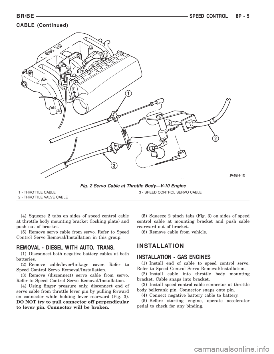
(4) Squeeze 2 tabs on sides of speed control cable
at throttle body mounting bracket (locking plate) and
push out of bracket.
(5) Remove servo cable from servo. Refer to Speed
Control Servo Removal/Installation in this group.
REMOVAL - DIESEL WITH AUTO. TRANS.
(1) Disconnect both negative battery cables at both
batteries.
(2) Remove cable/lever/linkage cover. Refer to
Speed Control Servo Removal/Installation.
(3) Remove (disconnect) servo cable from servo.
Refer to Speed Control Servo Removal/Installation.
(4) Using finger pressure only, disconnect end of
servo cable from throttle lever pin by pulling forward
on connector while holding lever rearward (Fig. 3).
DO NOT try to pull connector off perpendicular
to lever pin. Connector will be broken.(5) Squeeze 2 pinch tabs (Fig. 3) on sides of speed
control cable at mounting bracket and push cable
rearward out of bracket.
(6) Remove cable from vehicle.
INSTALLATION
INSTALLATION - GAS ENGINES
(1) Install end of cable to speed control servo.
Refer to Speed Control Servo Removal/Installation.
(2) Install cable into throttle body mounting
bracket. Cable snaps into bracket.
(3) Install speed control cable connector at throttle
body bellcrank pin. Connector snaps onto pin.
(4) Connect negative battery cable to battery.
(5) Before starting engine, operate accelerator
pedal to check for any binding.
Fig. 2 Servo Cable at Throttle BodyÐV-10 Engine
1 - THROTTLE CABLE
2 - THROTTLE VALVE CABLE3 - SPEED CONTROL SERVO CABLE
BR/BESPEED CONTROL 8P - 5
CABLE (Continued)
Page 640 of 2255
VEHICLE THEFT SECURITY
TABLE OF CONTENTS
page page
VEHICLE THEFT SECURITY
DESCRIPTION..........................1
OPERATION............................2
DIAGNOSIS AND TESTING - VEHICLE THEFT
SECURITY SYSTEM....................3VTSS INDICATOR
DESCRIPTION..........................3
OPERATION............................3
DIAGNOSIS AND TESTING - VTSS
INDICATOR...........................4
VEHICLE THEFT SECURITY
DESCRIPTION
The Vehicle Theft Security System (VTSS) is an
available factory-installed option on this model when
it is also equipped with the high-line or premium
Central Timer Module (CTM). The VTSS is designed
to provide perimeter protection against unauthorized
use or tampering by monitoring the vehicle doors and
the ignition system. If unauthorized vehicle use or
tampering is detected, the system responds by puls-
ing the horn, flashing the headlamps, and preventing
the engine from operating.
The VTSS includes the following major compo-
nents, which are described in further detail else-
where in this service manual:
²Central Timer Module- The high-line or pre-
mium Central Timer Module (CTM) is located under
the driver side end of the instrument panel, inboard
of the instrument panel steering column opening.
The high-line or premium CTM contains a micropro-
cessor and software that allow it to provide many
electronic functions and features not available with
base version of the CTM, including the VTSS. The
CTM provides all of the proper VTSS features and
outputs based upon the monitored inputs. The CTM
circuitry monitors hard wired switch inputs, as well
as message inputs received from other vehicle elec-
tronic modules over the Chrysler Collision Detection
(CCD) data bus network. (Refer to 8 - ELECTRICAL/
ELECTRONIC CONTROL MODULES/BODY CON-
TROL/CENTRAL TIMER MODULE -
DESCRIPTION).
²Door Ajar Switch- A door ajar switch is
located on the hinge pillar of each front door in the
vehicle. These switches provide an input to the VTSS
indicating whether the door is opened or closed.
(Refer to 8 - ELECTRICAL/LAMPS/LIGHTING -
INTERIOR/DOOR AJAR SWITCH - DESCRIPTION).
²Door Cylinder Lock Switch- A door cylinder
lock switch is located on the back of each front door
lock cylinder. This switch provides an input to theVTSS indicating whether the system should remain
armed or be disarmed. (Refer to 8 - ELECTRICAL/
POWER LOCKS/DOOR CYLINDER LOCK SWITCH
- DESCRIPTION).
²Horn Relay- The horn relay is located in the
Power Distribution Center (PDC) in the engine com-
partment near the battery. The horn relay is nor-
mally activated by the horn switch to control the
sounding of the vehicle horn or horns. However, it
can also be activated by an output of the Central
Timer Module (CTM) to provide an audible indication
that unauthorized vehicle use or tampering has been
detected. (Refer to 8 - ELECTRICAL/HORN/HORN
RELAY - DESCRIPTION).
²Headlamp Relay- The headlamp relay (also
known as the security relay) is located in the Power
Distribution Center (PDC) in the engine compart-
ment near the battery. The headlamp relay is nor-
mally activated by the Central Timer Module (CTM)
based upon inputs from the Remote Keyless Entry
(RKE) panic mode feature. However, it can also be
activated by an output of the CTM to flash the head-
lamp low beams to provide a highly visible indication
that unauthorized vehicle use or tampering has been
detected. (Refer to 8 - ELECTRICAL/LAMPS/LIGHT-
ING - EXTERIOR/HEADLAMP RELAY - DESCRIP-
TION).
²VTSS Indicator- A red Light Emitting Diode
(LED) located on the lower surface of the overhead
console near the windshield is illuminated by an out-
put of the Central Timer Module (CTM) to indicate
the status of the VTSS. This LED is integral to the
electronic circuit board for the Compass Mini-Trip
Computer (CMTC). (Refer to 8 - ELECTRICAL/
OVERHEAD CONSOLE/COMPASS/MINI-TRIP
COMPUTER - DESCRIPTION).
The engine no-run feature of the VTSS relies upon
communication between the high-line or premium
CTM and the Powertrain Control Module (PCM) over
the Chrysler Collision Detection (CCD) data bus net-
work.
BR/BEVEHICLE THEFT SECURITY 8Q - 1