2002 DODGE RAM differential
[x] Cancel search: differentialPage 1739 of 2255
STANDARD PROCEDURE - ALUMINUM
THREAD REPAIR
Damaged or worn threads in the aluminum trans-
mission case and valve body can be repaired by the
use of Heli-CoilsŸ, or equivalent. This repair con-
sists of drilling out the worn-out damaged threads.
Then tap the hole with a special Heli-CoilŸ tap, or
equivalent, and installing a Heli-CoilŸ insert, or
equivalent, into the hole. This brings the hole back to
its original thread size.
Heli-CoilŸ, or equivalent, tools and inserts are
readily available from most automotive parts suppli-
ers.
REMOVAL
The overdrive unit can be removed and serviced
separately. It is not necessary to remove the entire
transmission assembly to perform overdrive unit
repairs.
(1) Disconnect battery negative cable.
(2) Disconnect and lower or remove necessary
exhaust components.
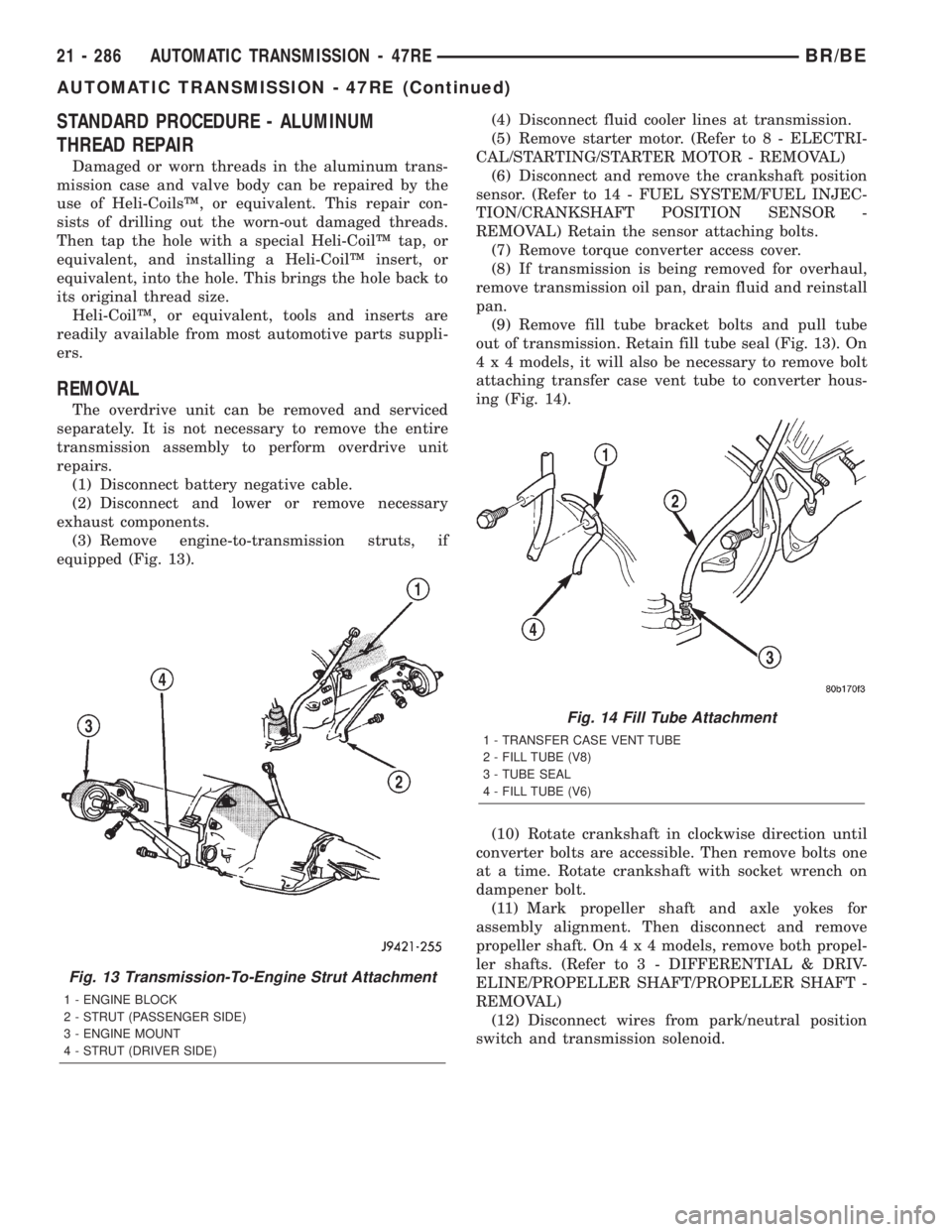
(3) Remove engine-to-transmission struts, if
equipped (Fig. 13).(4) Disconnect fluid cooler lines at transmission.
(5) Remove starter motor. (Refer to 8 - ELECTRI-
CAL/STARTING/STARTER MOTOR - REMOVAL)
(6) Disconnect and remove the crankshaft position
sensor. (Refer to 14 - FUEL SYSTEM/FUEL INJEC-
TION/CRANKSHAFT POSITION SENSOR -
REMOVAL) Retain the sensor attaching bolts.
(7) Remove torque converter access cover.
(8) If transmission is being removed for overhaul,
remove transmission oil pan, drain fluid and reinstall
pan.
(9) Remove fill tube bracket bolts and pull tube
out of transmission. Retain fill tube seal (Fig. 13). On
4 x 4 models, it will also be necessary to remove bolt
attaching transfer case vent tube to converter hous-
ing (Fig. 14).
(10) Rotate crankshaft in clockwise direction until
converter bolts are accessible. Then remove bolts one
at a time. Rotate crankshaft with socket wrench on
dampener bolt.
(11) Mark propeller shaft and axle yokes for
assembly alignment. Then disconnect and remove
propeller shaft. On4x4models, remove both propel-
ler shafts. (Refer to 3 - DIFFERENTIAL & DRIV-
ELINE/PROPELLER SHAFT/PROPELLER SHAFT -
REMOVAL)
(12) Disconnect wires from park/neutral position
switch and transmission solenoid.
Fig. 13 Transmission-To-Engine Strut Attachment
1 - ENGINE BLOCK
2 - STRUT (PASSENGER SIDE)
3 - ENGINE MOUNT
4 - STRUT (DRIVER SIDE)
Fig. 14 Fill Tube Attachment
1 - TRANSFER CASE VENT TUBE
2 - FILL TUBE (V8)
3 - TUBE SEAL
4 - FILL TUBE (V6)
21 - 286 AUTOMATIC TRANSMISSION - 47REBR/BE
AUTOMATIC TRANSMISSION - 47RE (Continued)
Page 1754 of 2255
(6) Check converter seating with steel scale and
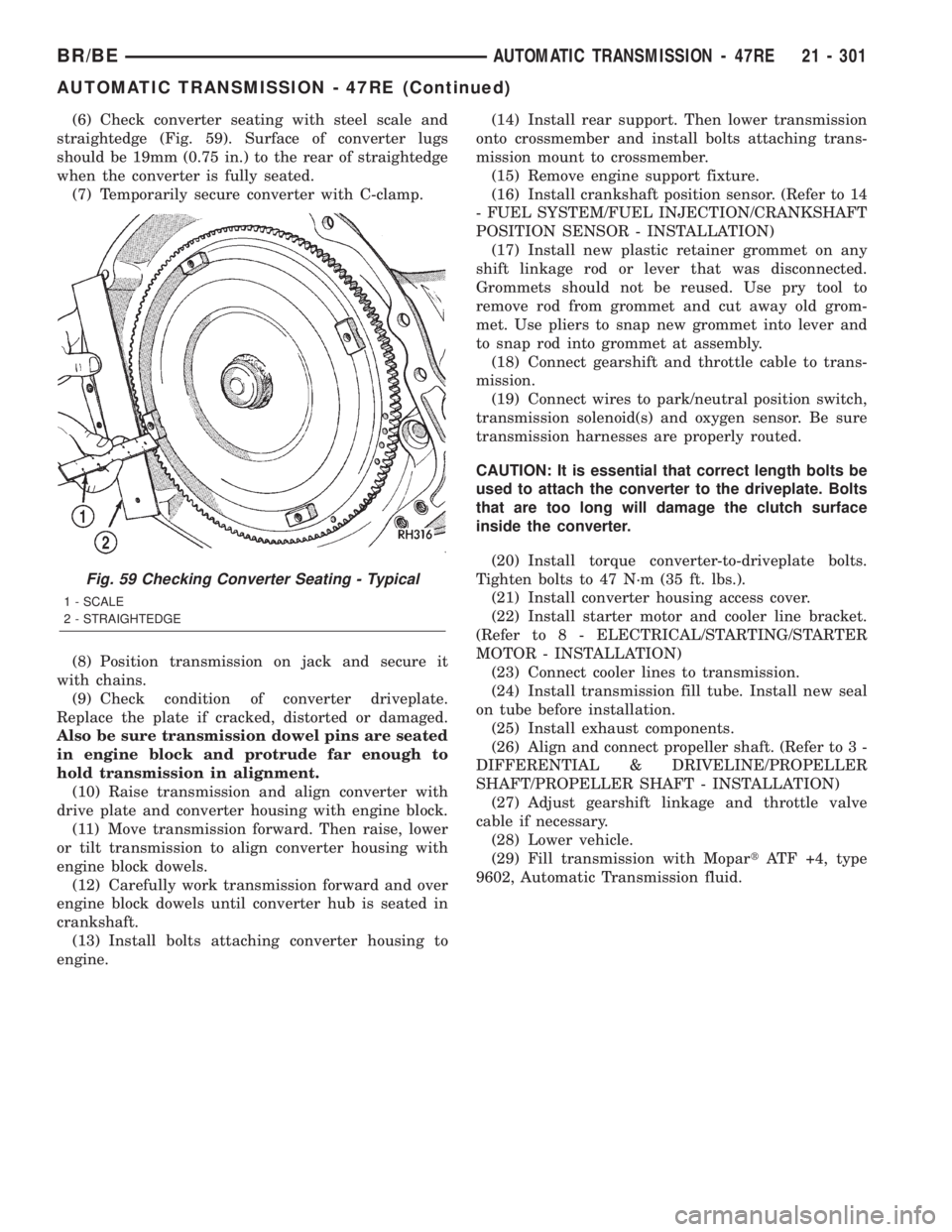
straightedge (Fig. 59). Surface of converter lugs
should be 19mm (0.75 in.) to the rear of straightedge
when the converter is fully seated.
(7) Temporarily secure converter with C-clamp.
(8) Position transmission on jack and secure it
with chains.
(9) Check condition of converter driveplate.
Replace the plate if cracked, distorted or damaged.
Also be sure transmission dowel pins are seated
in engine block and protrude far enough to
hold transmission in alignment.
(10) Raise transmission and align converter with
drive plate and converter housing with engine block.
(11) Move transmission forward. Then raise, lower
or tilt transmission to align converter housing with
engine block dowels.
(12) Carefully work transmission forward and over
engine block dowels until converter hub is seated in
crankshaft.
(13) Install bolts attaching converter housing to
engine.(14) Install rear support. Then lower transmission
onto crossmember and install bolts attaching trans-
mission mount to crossmember.
(15) Remove engine support fixture.
(16) Install crankshaft position sensor. (Refer to 14
- FUEL SYSTEM/FUEL INJECTION/CRANKSHAFT
POSITION SENSOR - INSTALLATION)
(17) Install new plastic retainer grommet on any
shift linkage rod or lever that was disconnected.
Grommets should not be reused. Use pry tool to
remove rod from grommet and cut away old grom-
met. Use pliers to snap new grommet into lever and
to snap rod into grommet at assembly.
(18) Connect gearshift and throttle cable to trans-
mission.
(19) Connect wires to park/neutral position switch,
transmission solenoid(s) and oxygen sensor. Be sure
transmission harnesses are properly routed.
CAUTION: It is essential that correct length bolts be
used to attach the converter to the driveplate. Bolts
that are too long will damage the clutch surface
inside the converter.
(20) Install torque converter-to-driveplate bolts.
Tighten bolts to 47 N´m (35 ft. lbs.).
(21) Install converter housing access cover.
(22) Install starter motor and cooler line bracket.
(Refer to 8 - ELECTRICAL/STARTING/STARTER
MOTOR - INSTALLATION)
(23) Connect cooler lines to transmission.
(24) Install transmission fill tube. Install new seal
on tube before installation.
(25) Install exhaust components.
(26) Align and connect propeller shaft. (Refer to 3 -
DIFFERENTIAL & DRIVELINE/PROPELLER
SHAFT/PROPELLER SHAFT - INSTALLATION)
(27) Adjust gearshift linkage and throttle valve
cable if necessary.
(28) Lower vehicle.
(29) Fill transmission with MopartATF +4, type
9602, Automatic Transmission fluid.
Fig. 59 Checking Converter Seating - Typical
1 - SCALE
2 - STRAIGHTEDGE
BR/BEAUTOMATIC TRANSMISSION - 47RE 21 - 301
AUTOMATIC TRANSMISSION - 47RE (Continued)
Page 1798 of 2255
INSTALLATION
NOTE: There is enough slack in the wire to pull out
the connector from the lever.
(1) Pull the connector out of the lever just enough
to grasp it.
CAUTION: Be careful not to bend the pins on the
overdrive off switch. Use care when installing the
switch, as it is not indexed, and can be accidentally
installed incorrectly.
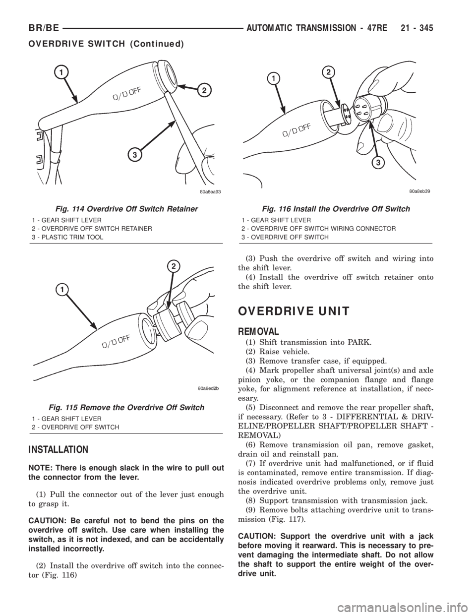
(2) Install the overdrive off switch into the connec-
tor (Fig. 116)(3) Push the overdrive off switch and wiring into
the shift lever.
(4) Install the overdrive off switch retainer onto
the shift lever.
OVERDRIVE UNIT
REMOVAL
(1) Shift transmission into PARK.
(2) Raise vehicle.
(3) Remove transfer case, if equipped.
(4) Mark propeller shaft universal joint(s) and axle
pinion yoke, or the companion flange and flange
yoke, for alignment reference at installation, if necc-
esary.
(5) Disconnect and remove the rear propeller shaft,
if necessary. (Refer to 3 - DIFFERENTIAL & DRIV-
ELINE/PROPELLER SHAFT/PROPELLER SHAFT -
REMOVAL)
(6) Remove transmission oil pan, remove gasket,
drain oil and reinstall pan.
(7) If overdrive unit had malfunctioned, or if fluid
is contaminated, remove entire transmission. If diag-
nosis indicated overdrive problems only, remove just
the overdrive unit.
(8) Support transmission with transmission jack.
(9) Remove bolts attaching overdrive unit to trans-
mission (Fig. 117).
CAUTION: Support the overdrive unit with a jack
before moving it rearward. This is necessary to pre-
vent damaging the intermediate shaft. Do not allow
the shaft to support the entire weight of the over-
drive unit.
Fig. 114 Overdrive Off Switch Retainer
1 - GEAR SHIFT LEVER
2 - OVERDRIVE OFF SWITCH RETAINER
3 - PLASTIC TRIM TOOL
Fig. 115 Remove the Overdrive Off Switch
1 - GEAR SHIFT LEVER
2 - OVERDRIVE OFF SWITCH
Fig. 116 Install the Overdrive Off Switch
1 - GEAR SHIFT LEVER
2 - OVERDRIVE OFF SWITCH WIRING CONNECTOR
3 - OVERDRIVE OFF SWITCH
BR/BEAUTOMATIC TRANSMISSION - 47RE 21 - 345
OVERDRIVE SWITCH (Continued)
Page 1816 of 2255
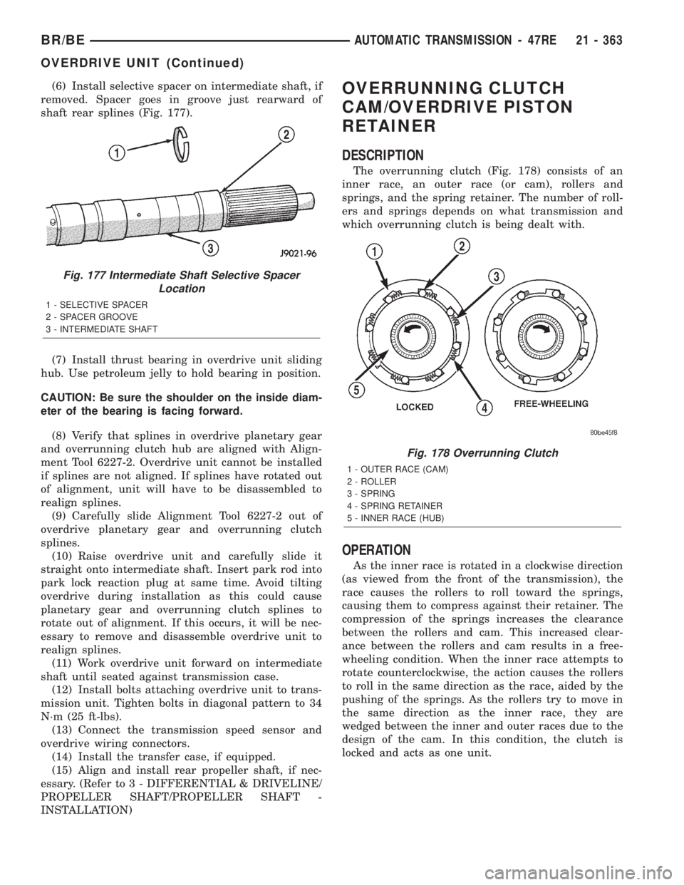
(6) Install selective spacer on intermediate shaft, if
removed. Spacer goes in groove just rearward of
shaft rear splines (Fig. 177).
(7) Install thrust bearing in overdrive unit sliding
hub. Use petroleum jelly to hold bearing in position.
CAUTION: Be sure the shoulder on the inside diam-
eter of the bearing is facing forward.
(8) Verify that splines in overdrive planetary gear
and overrunning clutch hub are aligned with Align-
ment Tool 6227-2. Overdrive unit cannot be installed
if splines are not aligned. If splines have rotated out
of alignment, unit will have to be disassembled to
realign splines.
(9) Carefully slide Alignment Tool 6227-2 out of
overdrive planetary gear and overrunning clutch
splines.
(10) Raise overdrive unit and carefully slide it
straight onto intermediate shaft. Insert park rod into
park lock reaction plug at same time. Avoid tilting
overdrive during installation as this could cause
planetary gear and overrunning clutch splines to
rotate out of alignment. If this occurs, it will be nec-
essary to remove and disassemble overdrive unit to
realign splines.
(11) Work overdrive unit forward on intermediate
shaft until seated against transmission case.
(12) Install bolts attaching overdrive unit to trans-
mission unit. Tighten bolts in diagonal pattern to 34
N´m (25 ft-lbs).
(13) Connect the transmission speed sensor and
overdrive wiring connectors.
(14) Install the transfer case, if equipped.
(15) Align and install rear propeller shaft, if nec-
essary. (Refer to 3 - DIFFERENTIAL & DRIVELINE/
PROPELLER SHAFT/PROPELLER SHAFT -
INSTALLATION)OVERRUNNING CLUTCH
CAM/OVERDRIVE PISTON
RETAINER
DESCRIPTION
The overrunning clutch (Fig. 178) consists of an
inner race, an outer race (or cam), rollers and
springs, and the spring retainer. The number of roll-
ers and springs depends on what transmission and
which overrunning clutch is being dealt with.
OPERATION
As the inner race is rotated in a clockwise direction
(as viewed from the front of the transmission), the
race causes the rollers to roll toward the springs,
causing them to compress against their retainer. The
compression of the springs increases the clearance
between the rollers and cam. This increased clear-
ance between the rollers and cam results in a free-
wheeling condition. When the inner race attempts to
rotate counterclockwise, the action causes the rollers
to roll in the same direction as the race, aided by the
pushing of the springs. As the rollers try to move in
the same direction as the inner race, they are
wedged between the inner and outer races due to the
design of the cam. In this condition, the clutch is
locked and acts as one unit.
Fig. 177 Intermediate Shaft Selective Spacer
Location
1 - SELECTIVE SPACER
2 - SPACER GROOVE
3 - INTERMEDIATE SHAFT
Fig. 178 Overrunning Clutch
1 - OUTER RACE (CAM)
2 - ROLLER
3 - SPRING
4 - SPRING RETAINER
5 - INNER RACE (HUB)
BR/BEAUTOMATIC TRANSMISSION - 47RE 21 - 363
OVERDRIVE UNIT (Continued)
Page 1858 of 2255
The higher engine speed and line pressure would
open the vent too far and reduce line pressure too
much. Throttle pressure, which increases with engine
speed (throttle opening), is used to oppose the move-
ment of the pressure valve to help control the meter-
ing passage at the vent. The throttle pressure is
combined with spring pressure to reduce the force of
the throttle pressure plug on the pressure valve. The
larger spring at the right closes the regulator valve
passage and maintains or increases line pressure.
The increased line pressure works against the reac-
tion area of the line pressure plug and the reaction
area left of land #3 simultaneously moves the regu-
lator valve train to the right and controls the meter-
ing passage.
The kickdown valve, along with the throttle valve,
serve to delay upshifts until the correct vehicle speed
has been reached. It also controls downshifts upon
driver demand, or increased engine load. If these
valves were not in place, the shift points would be at
the same speed for all throttle positions. The kick-
down valve is actuated by a cam connected to the
throttle. This is accomplished through either a link-
age or a cable. The cam forces the kickdown valve
toward the throttle valve compressing the spring
between them and moving the throttle valve. As the
throttle valve land starts to uncover its port, line
pressure is ªmeteredº out into the circuits and viewed
as throttle pressure. This increased throttle pressure
is metered out into the circuits it is applied to: the
1-2 and 2-3 shift valves. When the throttle pressure
is high enough, a 3-2 downshift will occur. If the
vehicle speed is low enough, a 2-1 downshift will
occur.
SWITCH VALVE
When the transmission is in Drive Second before
the TCC application occurs (Fig. 258), the pressure
regulator valve is supplying torque converter pres-
sure to the switch valve. The switch valve directs
this pressure through the transmission input shaft,
into the converter, through the converter, back out
between the input shaft and the reaction shaft, and
back up to the switch valve. From the switch valve,
the fluid pressure is directed to the transmission
cooler, and lubrication pressure returns from the
cooler to lubricate different portions of the transmis-
sion.Once the TCC control valve has moved to the right
(Fig. 259), line pressure is directed to the tip of the
switch valve, forcing the valve to the right. The
switch valve now vents oil from the front of the pis-
ton in the torque converter, and supplies line pres-
sure to the (rear) apply side of the torque converter
piston. This pressure differential causes the piston to
apply against the friction material, cutting off any
further flow of line pressure oil. After the switch
valve is shuttled right allowing line pressure to
engage the TCC, torque converter pressure is
directed past the switch valve into the transmission
cooler and lubrication circuits.
MANUAL VALVE
The manual valve (Fig. 260) is a relay valve. The
purpose of the manual valve is to direct fluid to the
correct circuit needed for a specific gear or driving
range. The manual valve, as the name implies, is
manually operated by the driver with a lever located
on the side of the valve body. The valve is connected
mechanically by either a cable or linkage to the gear-
shift mechanism. The valve is held in each of its
positions by a spring-loaded roller or ball that
engages the ªroostercombº of the manual valve lever.
CONVERTER CLUTCH LOCK-UP VALVE
The torque converter clutch (TCC) lock-up valve
controls the back (ON) side of the torque converter
clutch. When the PCM energizes the TCC solenoid to
engage the converter clutch piston, pressure is
applied to the TCC lock-up valve which moves to the
right and applies pressure to the torque converter
clutch.
CONVERTER CLUTCH LOCK-UP TIMING VALVE
The torque converter clutch (TCC) lock-up timing
valve is there to block any 4-3 downshift until the
TCC is completely unlocked and the clutch is disen-
gaged.
BR/BEAUTOMATIC TRANSMISSION - 47RE 21 - 405
VALVE BODY (Continued)
Page 1885 of 2255
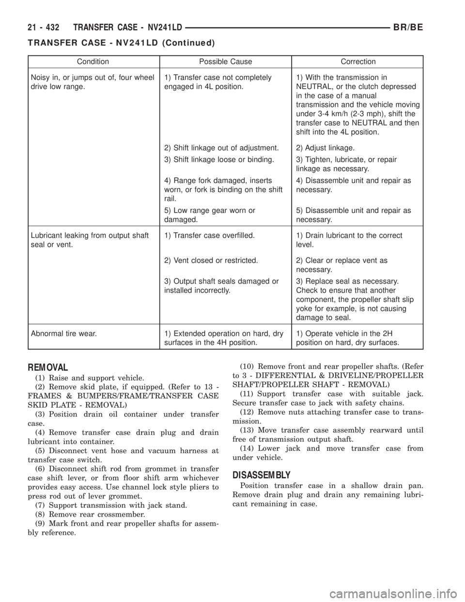
Condition Possible Cause Correction
Noisy in, or jumps out of, four wheel
drive low range.1) Transfer case not completely
engaged in 4L position.1) With the transmission in
NEUTRAL, or the clutch depressed
in the case of a manual
transmission and the vehicle moving
under 3-4 km/h (2-3 mph), shift the
transfer case to NEUTRAL and then
shift into the 4L position.
2) Shift linkage out of adjustment. 2) Adjust linkage.
3) Shift linkage loose or binding. 3) Tighten, lubricate, or repair
linkage as necessary.
4) Range fork damaged, inserts
worn, or fork is binding on the shift
rail.4) Disassemble unit and repair as
necessary.
5) Low range gear worn or
damaged.5) Disassemble unit and repair as
necessary.
Lubricant leaking from output shaft
seal or vent.1) Transfer case overfilled. 1) Drain lubricant to the correct
level.
2) Vent closed or restricted. 2) Clear or replace vent as
necessary.
3) Output shaft seals damaged or
installed incorrectly.3) Replace seal as necessary.
Check to ensure that another
component, the propeller shaft slip
yoke for example, is not causing
damage to seal.
Abnormal tire wear. 1) Extended operation on hard, dry
surfaces in the 4H position.1) Operate vehicle in the 2H
position on hard, dry surfaces.
REMOVAL
(1) Raise and support vehicle.
(2) Remove skid plate, if equipped. (Refer to 13 -
FRAMES & BUMPERS/FRAME/TRANSFER CASE
SKID PLATE - REMOVAL)
(3) Position drain oil container under transfer
case.
(4) Remove transfer case drain plug and drain
lubricant into container.
(5) Disconnect vent hose and vacuum harness at
transfer case switch.
(6) Disconnect shift rod from grommet in transfer
case shift lever, or from floor shift arm whichever
provides easy access. Use channel lock style pliers to
press rod out of lever grommet.
(7) Support transmission with jack stand.
(8) Remove rear crossmember.
(9) Mark front and rear propeller shafts for assem-
bly reference.(10) Remove front and rear propeller shafts. (Refer
to 3 - DIFFERENTIAL & DRIVELINE/PROPELLER
SHAFT/PROPELLER SHAFT - REMOVAL)
(11) Support transfer case with suitable jack.
Secure transfer case to jack with safety chains.
(12) Remove nuts attaching transfer case to trans-
mission.
(13) Move transfer case assembly rearward until
free of transmission output shaft.
(14) Lower jack and move transfer case from
under vehicle.
DISASSEMBLY
Position transfer case in a shallow drain pan.
Remove drain plug and drain any remaining lubri-
cant remaining in case.
21 - 432 TRANSFER CASE - NV241LDBR/BE
TRANSFER CASE - NV241LD (Continued)
Page 1911 of 2255
(11) Apply MopartSilicone Sealer to threads of
rear extension housing bolts. Then install and
tighten bolts to 27-34 N´m (20-25 ft. lbs.) torque.
INSTALLATION
(1) Align and seat transfer case on transmission.
Be sure transfer case input gear splines are aligned
with transmission output shaft. Align splines by
rotating transfer case rear output shaft yoke if nec-
essary. Do not install any transfer case attaching
nuts until the transfer case is completely seated
against the transmission.
(2) Install and tighten transfer case attaching
nuts. Tighten nuts to 30-41 N´m (20-30 ft.lbs.).
(3) Install rear crossmember.(4) Remove jack stand from under transmission.
(5) Align and connect propeller shafts. (Refer to 3 -
DIFFERENTIAL & DRIVELINE/PROPELLER
SHAFT/PROPELLER SHAFT - INSTALLATION)
(6) Connect vacuum harness and vent hose.
(7) Connect shift rod to transfer case lever or floor
shift arm. Use channel lock style pliers to press rod
back into lever grommet.
(8) Adjust shift linkage, if necessary.
(9) Fill transfer case with recommended transmis-
sion fluid and install fill plug.
(10) Install skid plate, if equipped. (Refer to 13 -
FRAMES & BUMPERS/FRAME/TRANSFER CASE
SKID PLATE - INSTALLATION)
(11) Lower vehicle
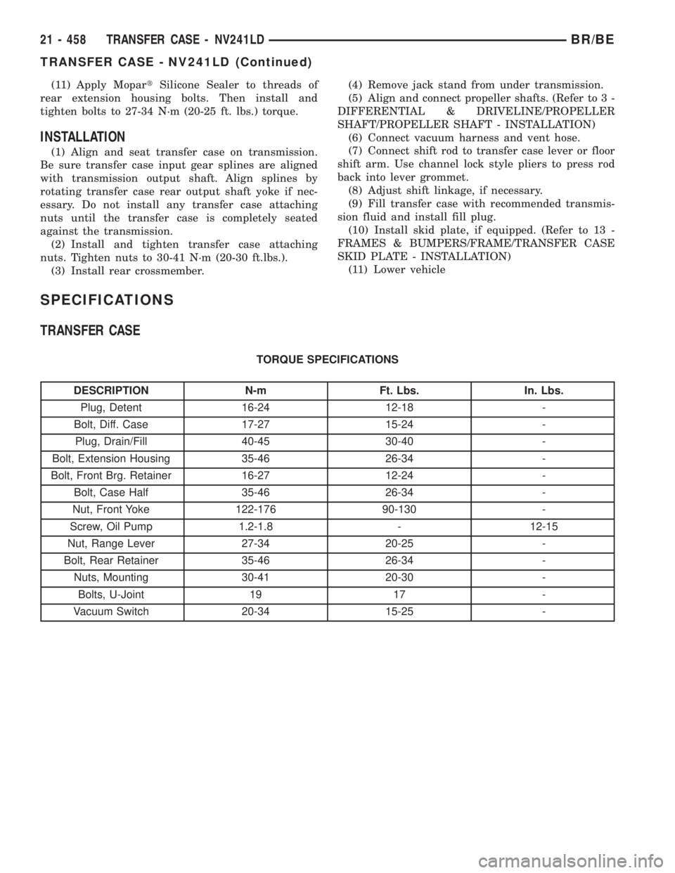
SPECIFICATIONS
TRANSFER CASE
TORQUE SPECIFICATIONS
DESCRIPTION N-m Ft. Lbs. In. Lbs.
Plug, Detent 16-24 12-18 -
Bolt, Diff. Case 17-27 15-24 -
Plug, Drain/Fill 40-45 30-40 -
Bolt, Extension Housing 35-46 26-34 -
Bolt, Front Brg. Retainer 16-27 12-24 -
Bolt, Case Half 35-46 26-34 -
Nut, Front Yoke 122-176 90-130 -
Screw, Oil Pump 1.2-1.8 - 12-15
Nut, Range Lever 27-34 20-25 -
Bolt, Rear Retainer 35-46 26-34 -
Nuts, Mounting 30-41 20-30 -
Bolts, U-Joint 19 17 -
Vacuum Switch 20-34 15-25 -
21 - 458 TRANSFER CASE - NV241LDBR/BE
TRANSFER CASE - NV241LD (Continued)
Page 1922 of 2255
REMOVAL
(1) Raise and support vehicle.
(2) Remove skid plate, if equipped. (Refer to 13 -
FRAMES & BUMPERS/FRAME/TRANSFER CASE
SKID PLATE - REMOVAL)
(3) Position drain oil container under transfer
case.
(4) Remove transfer case drain plug and drain
lubricant into container.
(5) Disconnect vent hose and vacuum harness at
transfer case switch.
(6) Disconnect shift rod from grommet in transfer
case shift lever, or from floor shift arm whichever
provides easy access. Use channel lock style pliers to
press rod out of lever grommet.
(7) Support transmission with jack stand.
(8) Remove rear crossmember.
(9) Mark front and rear propeller shafts for assem-
bly reference.
(10) Remove front and rear propeller shafts. (Refer
to 3 - DIFFERENTIAL & DRIVELINE/PROPELLER
SHAFT/PROPELLER SHAFT - REMOVAL)
(11) Support transfer case with suitable jack.
Secure transfer case to jack with safety chains.
(12) Remove nuts attaching transfer case to trans-
mission.
(13) Move transfer case assembly rearward until
free of transmission output shaft.
(14) Lower jack and move transfer case from
under vehicle.
DISASSEMBLY
Position transfer case in a shallow drain pan.
Remove drain plug and drain any remaining lubri-
cant remaining in case.
EXTENSION HOUSING
(1) Remove extension housing snap-ring access
cover.
(2) Remove bolts holding extension housing to rear
case half.
(3) Tap extension housing with plastic or rawhide
hammer to loosen sealant.
(4) Disengage extension housing snap-ring from
rear output shaft bearing.
(5) Separate extension housing from transfer case.
COMPANION FLANGE AND SHIFT LEVER
(1) Shift transfer case into NEUTRAL.
(2) Remove companion flange nut (Fig. 3). Discard
nut after removal. It is not reusable.
(3) Remove companion flange from front output
shaft. Use a suitable puller if flange can not be
removed by hand.
(4) Remove companion flange rubber seal from
front output shaft (Fig. 4).(5) Remove nut and washer that retain shift lever
to sector shaft. Then remove shift lever from shaft
(Fig. 5).
FRONT OUTPUT SHAFT AND DRIVE CHAIN
(1) Remove output bearing retaining ring with
heavy duty snap-ring pliers.
(2) Remove output shaft bearing.
(3) Note position of bolts that attach rear case to
front case (Fig. 6). Some bolts/studs at ends of case
Fig. 3 Removing Companion Flange Nut
1 - COMPANION FLANGE
2 - 1-1/8º SOCKET
Fig. 4 Companion Flange Seal Removal
1 - FLANGE SEAL
Fig. 5 Shift Lever Removal
1 - SHIFT LEVER
2 - NUT/WASHER
BR/BETRANSFER CASE - NV241HD 21 - 469
TRANSFER CASE - NV241HD (Continued)