2002 DODGE RAM differential
[x] Cancel search: differentialPage 1392 of 2255
DIAGNOSIS AND TESTING - BOOST PRESSURE
Two pressure gauges attached at two different
points are required for this test.(1) Obtain two 6828 fuel pressure test gauges
(equivalent gauges are OK).Gauge Consistency
Test:Connect the gauges together to a common pres-
sure source and verify pressure consistency of both
gauges. Do this consistency test at approximately 206
kPa (30 psi). If pressures are different, they can still
be used for test. Note and record differences in pres-
sures before testing. Make adjustments as necessary.
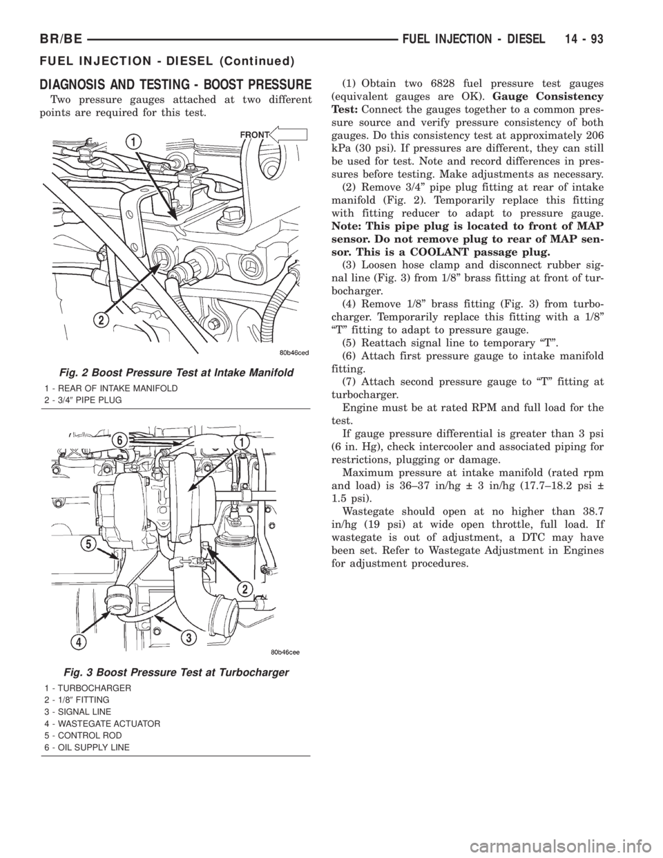
(2) Remove 3/4º pipe plug fitting at rear of intake
manifold (Fig. 2). Temporarily replace this fitting
with fitting reducer to adapt to pressure gauge.
Note: This pipe plug is located to front of MAP
sensor. Do not remove plug to rear of MAP sen-
sor. This is a COOLANT passage plug.
(3) Loosen hose clamp and disconnect rubber sig-
nal line (Fig. 3) from 1/8º brass fitting at front of tur-
bocharger.
(4) Remove 1/8º brass fitting (Fig. 3) from turbo-
charger. Temporarily replace this fitting with a 1/8º
ªTº fitting to adapt to pressure gauge.
(5) Reattach signal line to temporary ªTº.
(6) Attach first pressure gauge to intake manifold
fitting.
(7) Attach second pressure gauge to ªTº fitting at
turbocharger.
Engine must be at rated RPM and full load for the
test.
If gauge pressure differential is greater than 3 psi
(6 in. Hg), check intercooler and associated piping for
restrictions, plugging or damage.
Maximum pressure at intake manifold (rated rpm
and load) is 36±37 in/hg 3 in/hg (17.7±18.2 psi
1.5 psi).
Wastegate should open at no higher than 38.7
in/hg (19 psi) at wide open throttle, full load. If
wastegate is out of adjustment, a DTC may have
been set. Refer to Wastegate Adjustment in Engines
for adjustment procedures.
Fig. 2 Boost Pressure Test at Intake Manifold
1 - REAR OF INTAKE MANIFOLD
2 - 3/49PIPE PLUG
Fig. 3 Boost Pressure Test at Turbocharger
1 - TURBOCHARGER
2 - 1/89FITTING
3 - SIGNAL LINE
4 - WASTEGATE ACTUATOR
5 - CONTROL ROD
6 - OIL SUPPLY LINE
BR/BEFUEL INJECTION - DIESEL 14 - 93
FUEL INJECTION - DIESEL (Continued)
Page 1550 of 2255
DIAGNOSIS AND TESTING - PRELIMINARY
Two basic procedures are required. One procedure
for vehicles that are drivable and an alternate proce-
dure for disabled vehicles (will not back up or move
forward).
VEHICLE IS DRIVEABLE
(1) Check for transmission fault codes using DRBt
scan tool.
(2) Check fluid level and condition.
(3) Adjust throttle and gearshift linkage if com-
plaint was based on delayed, erratic, or harsh shifts.
(4) Road test and note how transmission upshifts,
downshifts, and engages.
(5) Perform hydraulic pressure test if shift prob-
lems were noted during road test.
(6) Perform air-pressure test to check clutch-band
operation.
VEHICLE IS DISABLED
(1) Check fluid level and condition.
(2) Check for broken or disconnected gearshift or
throttle linkage.
(3) Check for cracked, leaking cooler lines, or loose
or missing pressure-port plugs.
(4) Raise and support vehicle on safety stands,
start engine, shift transmission into gear, and note
following:
(a) If propeller shaft turns but wheels do not,
problem is with differential or axle shafts.(b) If propeller shaft does not turn and transmis-
sion is noisy, stop engine. Remove oil pan, and
check for debris. If pan is clear, remove transmis-
sion and check for damaged drive plate, converter,
oil pump, or input shaft.
(c) If propeller shaft does not turn and transmis-
sion is not noisy, perform hydraulic-pressure test to
determine if problem is hydraulic or mechanical.
DIAGNOSIS AND TESTING - ROAD TESTING
Before road testing, be sure the fluid level and con-
trol cable adjustments have been checked and
adjusted if necessary. Verify that diagnostic trouble
codes have been resolved.
Observe engine performance during the road test.
A poorly tuned engine will not allow accurate analy-
sis of transmission operation.
Operate the transmission in all gear ranges. Check
for shift variations and engine flare which indicates
slippage. Note if shifts are harsh, spongy, delayed,
early, or if part throttle downshifts are sensitive.
Slippage indicated by engine flare, usually means
clutch, band or overrunning clutch problems. If the
condition is advanced, an overhaul will be necessary
to restore normal operation.
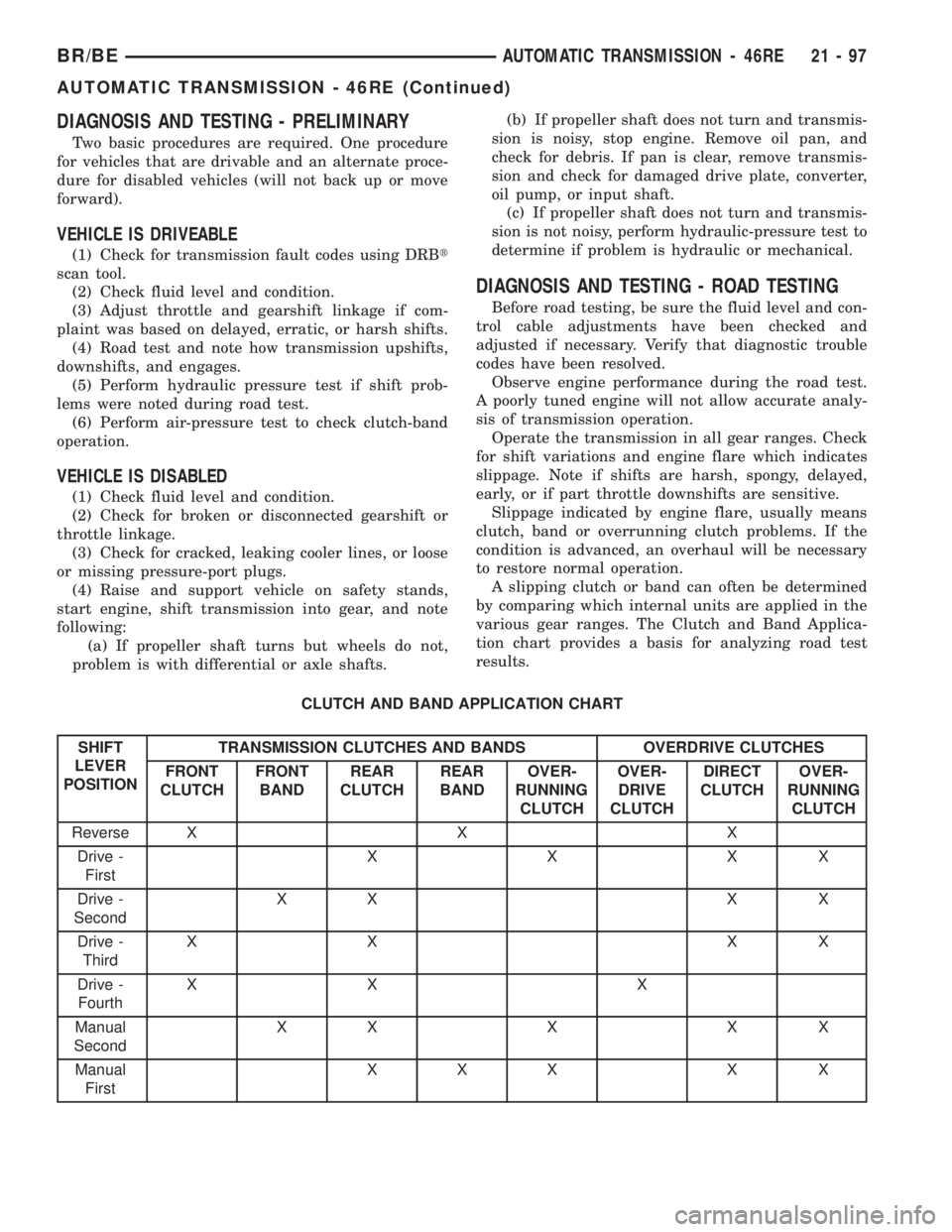
A slipping clutch or band can often be determined
by comparing which internal units are applied in the
various gear ranges. The Clutch and Band Applica-
tion chart provides a basis for analyzing road test
results.
CLUTCH AND BAND APPLICATION CHART
SHIFT
LEVER
POSITIONTRANSMISSION CLUTCHES AND BANDS OVERDRIVE CLUTCHES
FRONT
CLUTCHFRONT
BANDREAR
CLUTCHREAR
BANDOVER-
RUNNING
CLUTCHOVER-
DRIVE
CLUTCHDIRECT
CLUTCHOVER-
RUNNING
CLUTCH
Reverse X X X
Drive -
FirstXXXX
Drive -
SecondXX X X
Drive -
ThirdXX XX
Drive -
FourthXX X
Manual
SecondXXXXX
Manual
FirstXXX X X
BR/BEAUTOMATIC TRANSMISSION - 46RE 21 - 97
AUTOMATIC TRANSMISSION - 46RE (Continued)
Page 1567 of 2255
STANDARD PROCEDURE - ALUMINUM
THREAD REPAIR
Damaged or worn threads in the aluminum trans-
mission case and valve body can be repaired by the
use of Heli-CoilsŸ, or equivalent. This repair con-
sists of drilling out the worn-out damaged threads.
Then tap the hole with a special Heli-CoilŸ tap, or
equivalent, and installing a Heli-CoilŸ insert, or
equivalent, into the hole. This brings the hole back to
its original thread size.
Heli-CoilŸ, or equivalent, tools and inserts are
readily available from most automotive parts suppli-
ers.
REMOVAL
The overdrive unit can be removed and serviced
separately. It is not necessary to remove the entire
transmission assembly to perform overdrive unit
repairs.
(1) Disconnect battery negative cable.
(2) Disconnect and lower or remove necessary
exhaust components.
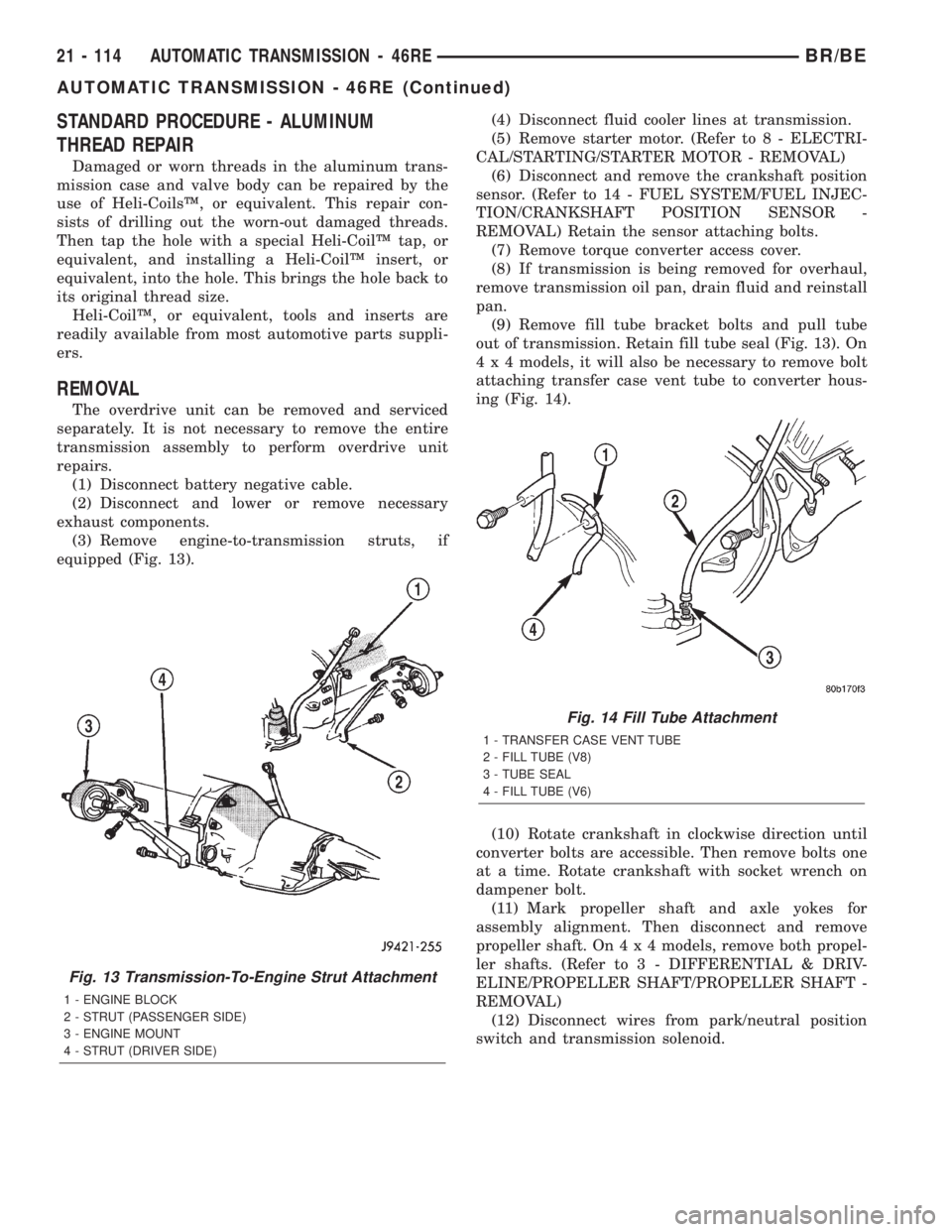
(3) Remove engine-to-transmission struts, if
equipped (Fig. 13).(4) Disconnect fluid cooler lines at transmission.
(5) Remove starter motor. (Refer to 8 - ELECTRI-
CAL/STARTING/STARTER MOTOR - REMOVAL)
(6) Disconnect and remove the crankshaft position
sensor. (Refer to 14 - FUEL SYSTEM/FUEL INJEC-
TION/CRANKSHAFT POSITION SENSOR -
REMOVAL) Retain the sensor attaching bolts.
(7) Remove torque converter access cover.
(8) If transmission is being removed for overhaul,
remove transmission oil pan, drain fluid and reinstall
pan.
(9) Remove fill tube bracket bolts and pull tube
out of transmission. Retain fill tube seal (Fig. 13). On
4 x 4 models, it will also be necessary to remove bolt
attaching transfer case vent tube to converter hous-
ing (Fig. 14).
(10) Rotate crankshaft in clockwise direction until
converter bolts are accessible. Then remove bolts one
at a time. Rotate crankshaft with socket wrench on
dampener bolt.
(11) Mark propeller shaft and axle yokes for
assembly alignment. Then disconnect and remove
propeller shaft. On4x4models, remove both propel-
ler shafts. (Refer to 3 - DIFFERENTIAL & DRIV-
ELINE/PROPELLER SHAFT/PROPELLER SHAFT -
REMOVAL)
(12) Disconnect wires from park/neutral position
switch and transmission solenoid.
Fig. 13 Transmission-To-Engine Strut Attachment
1 - ENGINE BLOCK
2 - STRUT (PASSENGER SIDE)
3 - ENGINE MOUNT
4 - STRUT (DRIVER SIDE)
Fig. 14 Fill Tube Attachment
1 - TRANSFER CASE VENT TUBE
2 - FILL TUBE (V8)
3 - TUBE SEAL
4 - FILL TUBE (V6)
21 - 114 AUTOMATIC TRANSMISSION - 46REBR/BE
AUTOMATIC TRANSMISSION - 46RE (Continued)
Page 1584 of 2255
(16) Install crankshaft position sensor. (Refer to 14
- FUEL SYSTEM/FUEL INJECTION/CRANKSHAFT
POSITION SENSOR - INSTALLATION)
(17) Install new plastic retainer grommet on any
shift linkage rod or lever that was disconnected.
Grommets should not be reused. Use pry tool to
remove rod from grommet and cut away old grom-
met. Use pliers to snap new grommet into lever and
to snap rod into grommet at assembly.
(18) Connect gearshift and throttle cable to trans-
mission.
(19) Connect wires to park/neutral position switch,
transmission solenoid(s) and oxygen sensor. Be sure
transmission harnesses are properly routed.
CAUTION: It is essential that correct length bolts be
used to attach the converter to the driveplate. Bolts
that are too long will damage the clutch surface
inside the converter.
(20) Install torque converter-to-driveplate bolts.
On models with 10.75 in. converter, tighten bolts to31 N´m (270 in. lbs.). On models with 12.2 in. con-
verter, tighten bolts to 47 N´m (35 ft. lbs.).
(21) Install converter housing access cover.
(22) Install starter motor and cooler line bracket.
(Refer to 8 - ELECTRICAL/STARTING/STARTER
MOTOR - INSTALLATION)
(23) Connect cooler lines to transmission.
(24) Install transmission fill tube. Install new seal
on tube before installation.
(25) Install exhaust components.
(26) Align and connect propeller shaft. (Refer to 3 -
DIFFERENTIAL & DRIVELINE/PROPELLER
SHAFT/PROPELLER SHAFT - INSTALLATION)
(27) Adjust gearshift linkage and throttle valve
cable if necessary.
(28) Lower vehicle.
(29) Fill transmission with MopartATF +4, type
9602, Automatic Transmission fluid.
BR/BEAUTOMATIC TRANSMISSION - 46RE 21 - 131
AUTOMATIC TRANSMISSION - 46RE (Continued)
Page 1626 of 2255
OVERDRIVE UNIT
REMOVAL
(1) Shift transmission into PARK.
(2) Raise vehicle.
(3) Remove transfer case, if equipped.
(4) Mark propeller shaft universal joint(s) and axle
pinion yoke, or the companion flange and flange
yoke, for alignment reference at installation, if necc-
esary.
(5) Disconnect and remove the rear propeller shaft,
if necessary. (Refer to 3 - DIFFERENTIAL & DRIV-
ELINE/PROPELLER SHAFT/PROPELLER SHAFT -
REMOVAL)
(6) Remove transmission oil pan, remove gasket,
drain oil and reinstall pan.
(7) If overdrive unit had malfunctioned, or if fluid
is contaminated, remove entire transmission. If diag-
nosis indicated overdrive problems only, remove just
the overdrive unit.
(8) Support transmission with transmission jack.
(9) Remove bolts attaching overdrive unit to trans-
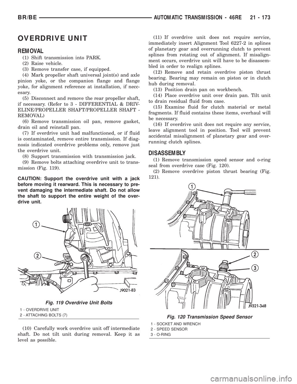
mission (Fig. 119).
CAUTION: Support the overdrive unit with a jack
before moving it rearward. This is necessary to pre-
vent damaging the intermediate shaft. Do not allow
the shaft to support the entire weight of the over-
drive unit.
(10) Carefully work overdrive unit off intermediate
shaft. Do not tilt unit during removal. Keep it as
level as possible.(11) If overdrive unit does not require service,
immediately insert Alignment Tool 6227-2 in splines
of planetary gear and overrunning clutch to prevent
splines from rotating out of alignment. If misalign-
ment occurs, overdrive unit will have to be disassem-
bled in order to realign splines.
(12) Remove and retain overdrive piston thrust
bearing. Bearing may remain on piston or in clutch
hub during removal.
(13) Position drain pan on workbench.
(14) Place overdrive unit over drain pan. Tilt unit
to drain residual fluid from case.
(15) Examine fluid for clutch material or metal
fragments. If fluid contains these items, overhaul will
be necessary.
(16) If overdrive unit does not require any service,
leave alignment tool in position. Tool will prevent
accidental misalignment of planetary gear and over-
running clutch splines.
DISASSEMBLY
(1) Remove transmission speed sensor and o-ring
seal from overdrive case (Fig. 120).
(2) Remove overdrive piston thrust bearing (Fig.
121).
Fig. 119 Overdrive Unit Bolts
1 - OVERDRIVE UNIT
2 - ATTACHING BOLTS (7)
Fig. 120 Transmission Speed Sensor
1 - SOCKET AND WRENCH
2 - SPEED SENSOR
3 - O-RING
BR/BEAUTOMATIC TRANSMISSION - 46RE 21 - 173
Page 1643 of 2255
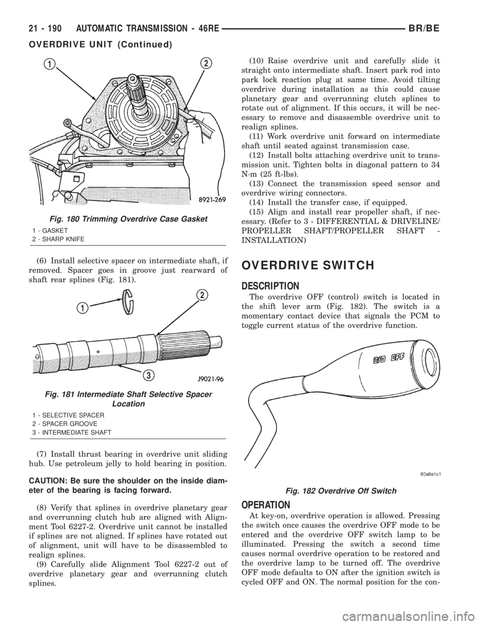
(6) Install selective spacer on intermediate shaft, if
removed. Spacer goes in groove just rearward of
shaft rear splines (Fig. 181).
(7) Install thrust bearing in overdrive unit sliding
hub. Use petroleum jelly to hold bearing in position.
CAUTION: Be sure the shoulder on the inside diam-
eter of the bearing is facing forward.
(8) Verify that splines in overdrive planetary gear
and overrunning clutch hub are aligned with Align-
ment Tool 6227-2. Overdrive unit cannot be installed
if splines are not aligned. If splines have rotated out
of alignment, unit will have to be disassembled to
realign splines.
(9) Carefully slide Alignment Tool 6227-2 out of
overdrive planetary gear and overrunning clutch
splines.(10) Raise overdrive unit and carefully slide it
straight onto intermediate shaft. Insert park rod into
park lock reaction plug at same time. Avoid tilting
overdrive during installation as this could cause
planetary gear and overrunning clutch splines to
rotate out of alignment. If this occurs, it will be nec-
essary to remove and disassemble overdrive unit to
realign splines.
(11) Work overdrive unit forward on intermediate
shaft until seated against transmission case.
(12) Install bolts attaching overdrive unit to trans-
mission unit. Tighten bolts in diagonal pattern to 34
N´m (25 ft-lbs).
(13) Connect the transmission speed sensor and
overdrive wiring connectors.
(14) Install the transfer case, if equipped.
(15) Align and install rear propeller shaft, if nec-
essary. (Refer to 3 - DIFFERENTIAL & DRIVELINE/
PROPELLER SHAFT/PROPELLER SHAFT -
INSTALLATION)OVERDRIVE SWITCH
DESCRIPTION
The overdrive OFF (control) switch is located in
the shift lever arm (Fig. 182). The switch is a
momentary contact device that signals the PCM to
toggle current status of the overdrive function.
OPERATION
At key-on, overdrive operation is allowed. Pressing
the switch once causes the overdrive OFF mode to be
entered and the overdrive OFF switch lamp to be
illuminated. Pressing the switch a second time
causes normal overdrive operation to be restored and
the overdrive lamp to be turned off. The overdrive
OFF mode defaults to ON after the ignition switch is
cycled OFF and ON. The normal position for the con-
Fig. 180 Trimming Overdrive Case Gasket
1 - GASKET
2 - SHARP KNIFE
Fig. 181 Intermediate Shaft Selective Spacer
Location
1 - SELECTIVE SPACER
2 - SPACER GROOVE
3 - INTERMEDIATE SHAFT
Fig. 182 Overdrive Off Switch
21 - 190 AUTOMATIC TRANSMISSION - 46REBR/BE
OVERDRIVE UNIT (Continued)
Page 1687 of 2255
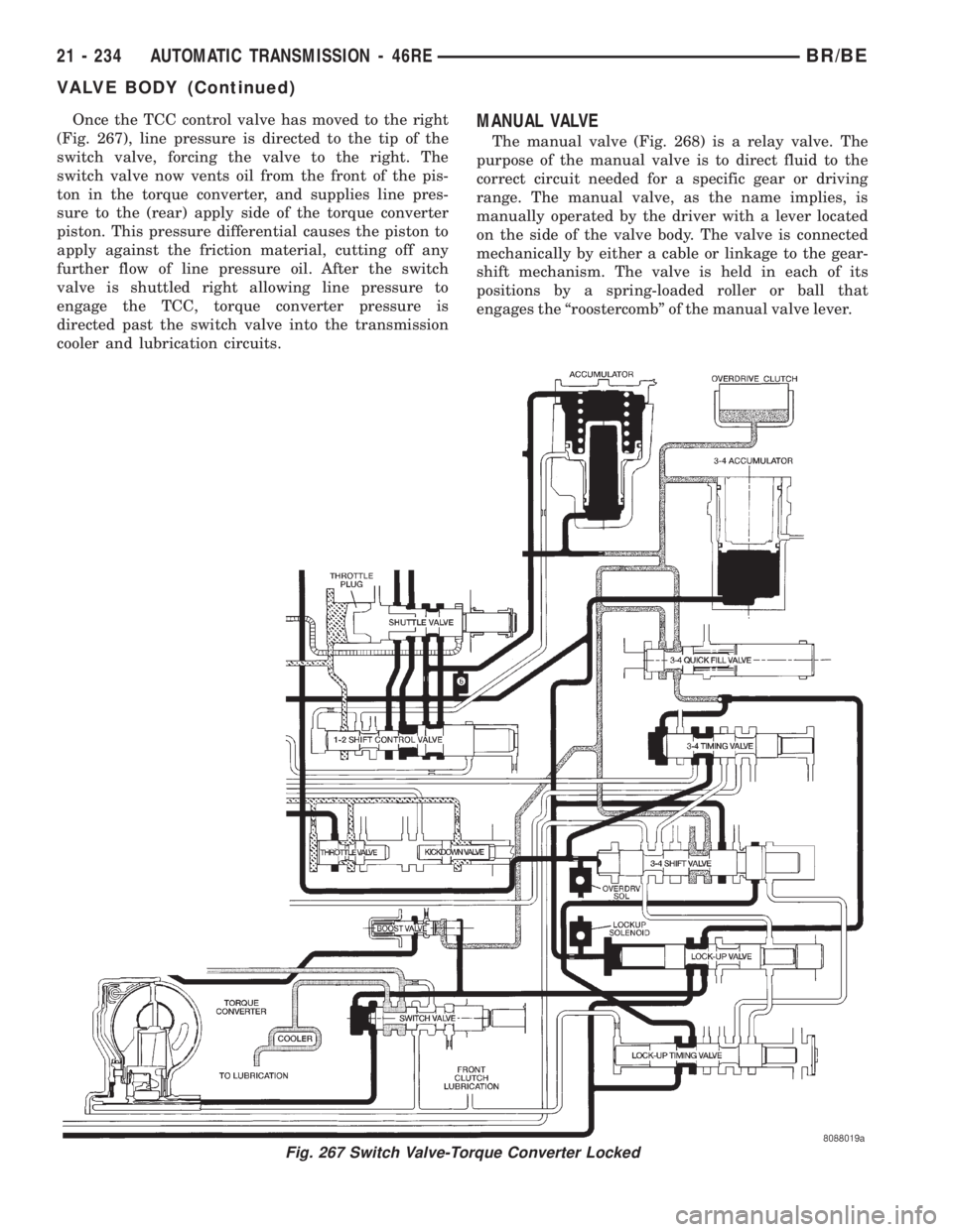
Once the TCC control valve has moved to the right
(Fig. 267), line pressure is directed to the tip of the
switch valve, forcing the valve to the right. The
switch valve now vents oil from the front of the pis-
ton in the torque converter, and supplies line pres-
sure to the (rear) apply side of the torque converter
piston. This pressure differential causes the piston to
apply against the friction material, cutting off any
further flow of line pressure oil. After the switch
valve is shuttled right allowing line pressure to
engage the TCC, torque converter pressure is
directed past the switch valve into the transmission
cooler and lubrication circuits.MANUAL VALVE
The manual valve (Fig. 268) is a relay valve. The
purpose of the manual valve is to direct fluid to the
correct circuit needed for a specific gear or driving
range. The manual valve, as the name implies, is
manually operated by the driver with a lever located
on the side of the valve body. The valve is connected
mechanically by either a cable or linkage to the gear-
shift mechanism. The valve is held in each of its
positions by a spring-loaded roller or ball that
engages the ªroostercombº of the manual valve lever.
Fig. 267 Switch Valve-Torque Converter Locked
21 - 234 AUTOMATIC TRANSMISSION - 46REBR/BE
VALVE BODY (Continued)
Page 1722 of 2255
DIAGNOSIS AND TESTING - PRELIMINARY
Two basic procedures are required. One procedure
for vehicles that are drivable and an alternate proce-
dure for disabled vehicles (will not back up or move
forward).
VEHICLE IS DRIVEABLE
(1) Check for transmission fault codes using DRBt
scan tool.
(2) Check fluid level and condition.
(3) Adjust throttle and gearshift linkage if com-
plaint was based on delayed, erratic, or harsh shifts.
(4) Road test and note how transmission upshifts,
downshifts, and engages.
(5) Perform hydraulic pressure test if shift prob-
lems were noted during road test.
(6) Perform air-pressure test to check clutch-band
operation.
VEHICLE IS DISABLED
(1) Check fluid level and condition.
(2) Check for broken or disconnected gearshift or
throttle linkage.
(3) Check for cracked, leaking cooler lines, or loose
or missing pressure-port plugs.
(4) Raise and support vehicle on safety stands,
start engine, shift transmission into gear, and note
following:
(a) If propeller shaft turns but wheels do not,
problem is with differential or axle shafts.(b) If propeller shaft does not turn and transmis-
sion is noisy, stop engine. Remove oil pan, and
check for debris. If pan is clear, remove transmis-
sion and check for damaged drive plate, converter,
oil pump, or input shaft.
(c) If propeller shaft does not turn and transmis-
sion is not noisy, perform hydraulic-pressure test to
determine if problem is hydraulic or mechanical.
DIAGNOSIS AND TESTING - ROAD TESTING
Before road testing, be sure the fluid level and con-
trol cable adjustments have been checked and
adjusted if necessary. Verify that diagnostic trouble
codes have been resolved.
Observe engine performance during the road test.
A poorly tuned engine will not allow accurate analy-
sis of transmission operation.
Operate the transmission in all gear ranges. Check
for shift variations and engine flare which indicates
slippage. Note if shifts are harsh, spongy, delayed,
early, or if part throttle downshifts are sensitive.
Slippage indicated by engine flare, usually means
clutch, band or overrunning clutch problems. If the
condition is advanced, an overhaul will be necessary
to restore normal operation.
A slipping clutch or band can often be determined
by comparing which internal units are applied in the
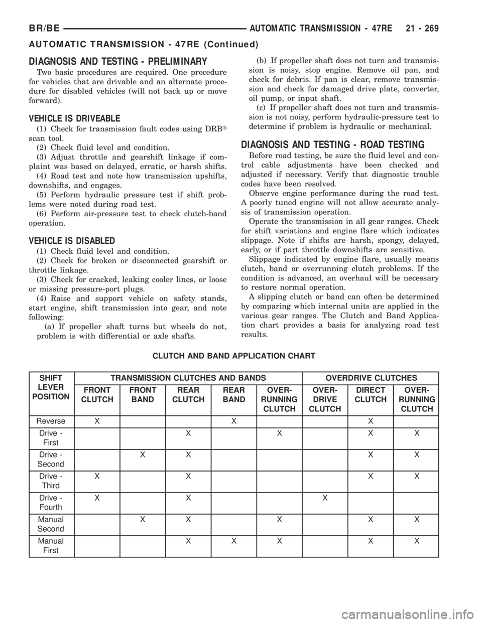
various gear ranges. The Clutch and Band Applica-
tion chart provides a basis for analyzing road test
results.
CLUTCH AND BAND APPLICATION CHART
SHIFT
LEVER
POSITIONTRANSMISSION CLUTCHES AND BANDS OVERDRIVE CLUTCHES
FRONT
CLUTCHFRONT
BANDREAR
CLUTCHREAR
BANDOVER-
RUNNING
CLUTCHOVER-
DRIVE
CLUTCHDIRECT
CLUTCHOVER-
RUNNING
CLUTCH
Reverse X X X
Drive -
FirstXXXX
Drive -
SecondXX X X
Drive -
ThirdXX XX
Drive -
FourthXX X
Manual
SecondXXXXX
Manual
FirstXXX X X
BR/BEAUTOMATIC TRANSMISSION - 47RE 21 - 269
AUTOMATIC TRANSMISSION - 47RE (Continued)