2002 DODGE RAM differential
[x] Cancel search: differentialPage 184 of 2255
with the flange cover half for installation in their
original positions.
ASSEMBLY
The Trac-Loktdifferential for this axle has a one-
piece cross shaft and uses one dished disc, 5 regular
disc and 7 plates for each clutch pack.
NOTE: The clutch discs are replaceable as com-
plete sets only. If one clutch disc pack is damaged,
both packs must be replaced.
Lubricate each component with gear lube before
assembly and installation.
(1) Saturate the clutch plates with Mopar Hypoid
Gear Lubricant or Additive.
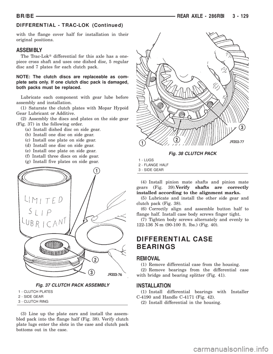
(2) Assembly the discs and plates on the side gear
(Fig. 37) in the following order.
(a) Install dished disc on side gear.
(b) Install one disc on side gear.
(c) Install one plate on side gear.
(d) Install one disc on side gear.
(e) Install one plate on side gear.
(f) Install three discs on side gear.
(g) Install five plates on side gear.
(3) Line up the plate ears and install the assem-
bled pack into the flange half (Fig. 38). Verify clutch
plate lugs enter the slots in the case and clutch pack
bottoms out in the case.(4) Install pinion mate shafts and pinion mate
gears (Fig. 39).Verify shafts are correctly
installed according to the alignment marks.
(5) Lubricate and install the other side gear and
clutch pack (Fig. 38).
(6) Correctly align and assemble button half to
flange half. Install case body screws finger tight.
(7) Tighten body screws alternately and evenly to
122-136 N´m (90-100 ft. lbs.) (Fig. 40).
DIFFERENTIAL CASE
BEARINGS
REMOVAL
(1) Remove differential case from the housing.
(2) Remove bearings from the differential case
with bridge and bearing splitter (Fig. 41).
INSTALLATION
(1) Install differential bearings with Installer
C-4190 and Handle C-4171 (Fig. 42).
(2) Install differential in the housing.
Fig. 37 CLUTCH PACK ASSEMBLY
1 - CLUTCH PLATES
2 - SIDE GEAR
3 - CLUTCH RING
Fig. 38 CLUTCH PACK
1 - LUGS
2 - FLANGE HALF
3 - SIDE GEAR
BR/BEREAR AXLE - 286RBI 3 - 129
DIFFERENTIAL - TRAC-LOK (Continued)
Page 185 of 2255
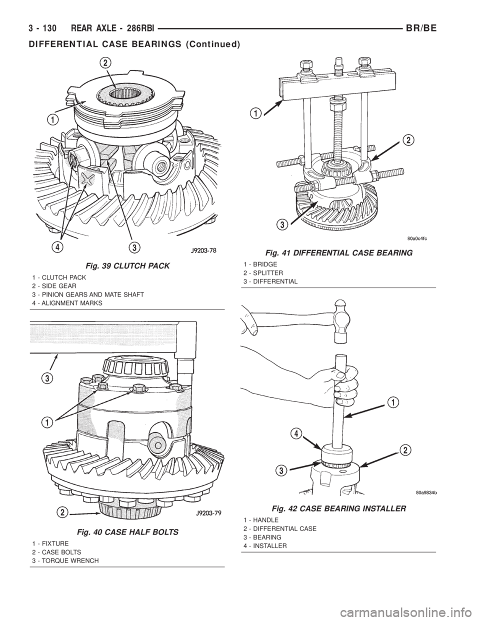
Fig. 39 CLUTCH PACK
1 - CLUTCH PACK
2 - SIDE GEAR
3 - PINION GEARS AND MATE SHAFT
4 - ALIGNMENT MARKS
Fig. 40 CASE HALF BOLTS
1 - FIXTURE
2 - CASE BOLTS
3 - TORQUE WRENCH
Fig. 41 DIFFERENTIAL CASE BEARING
1 - BRIDGE
2 - SPLITTER
3 - DIFFERENTIAL
Fig. 42 CASE BEARING INSTALLER
1 - HANDLE
2 - DIFFERENTIAL CASE
3 - BEARING
4 - INSTALLER
3 - 130 REAR AXLE - 286RBIBR/BE
DIFFERENTIAL CASE BEARINGS (Continued)
Page 186 of 2255
PINION GEAR/RING GEAR/
TONE RING
REMOVAL
NOTE: The ring and pinion gears are service as a
matched set. Never replace the ring gear without
replacing the matched pinion gear.
(1) Remove differential from the housing.
(2) Place differential case in a vise with soft metal
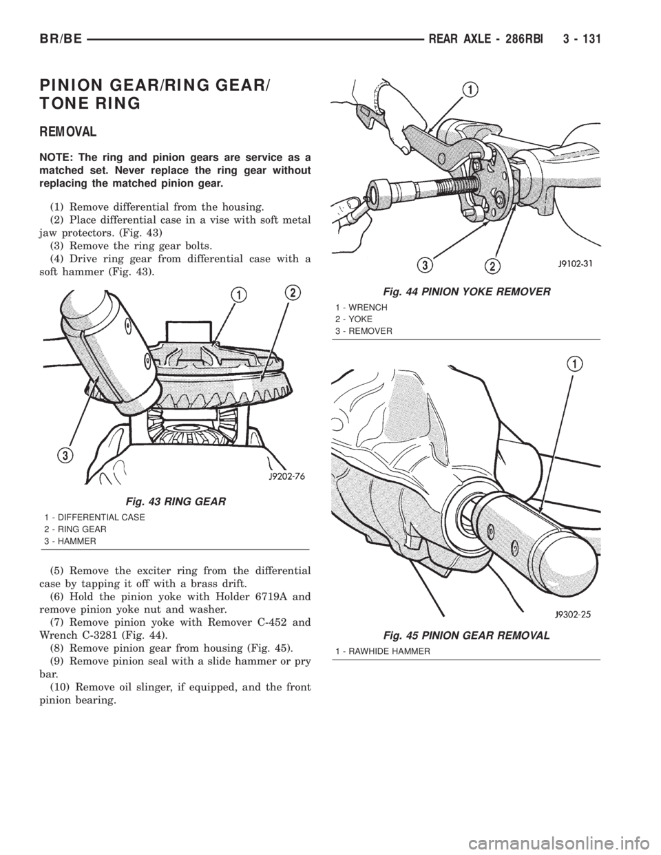
jaw protectors. (Fig. 43)
(3) Remove the ring gear bolts.
(4) Drive ring gear from differential case with a
soft hammer (Fig. 43).
(5) Remove the exciter ring from the differential
case by tapping it off with a brass drift.
(6) Hold the pinion yoke with Holder 6719A and
remove pinion yoke nut and washer.
(7) Remove pinion yoke with Remover C-452 and
Wrench C-3281 (Fig. 44).
(8) Remove pinion gear from housing (Fig. 45).
(9) Remove pinion seal with a slide hammer or pry
bar.
(10) Remove oil slinger, if equipped, and the front
pinion bearing.
Fig. 43 RING GEAR
1 - DIFFERENTIAL CASE
2 - RING GEAR
3 - HAMMER
Fig. 44 PINION YOKE REMOVER
1 - WRENCH
2 - YOKE
3 - REMOVER
Fig. 45 PINION GEAR REMOVAL
1 - RAWHIDE HAMMER
BR/BEREAR AXLE - 286RBI 3 - 131
Page 189 of 2255

(10) Check bearing rotating torque with an inch
pound torque wrench (Fig. 54). Pinion rotating torque
should be:
²Original Bearings: 1 to 3 N´m (10 to 20 in. lbs.).
²New Bearings: 2.8 to 5.1 N´m (25 to 45 in. lbs.).
(11) If rotating torque is less than the desired
rotating torque, remove the pinion yoke and decrease
the thickness of the solid shim pack if greater
increase shim pack. Changing the shim pack thick-
ness by 0.025 mm (0.001 in.) will change the rotating
torque approximately 0.9 N´m (8 in. lbs.).
(12) Invert the differential case.
(13) Position exciter ring on differential case and
tap onto the case with a brass drift slowly and
evenly.
(14) Invert differential case and start two ring
gear bolts. This will provide case-to-ring gear bolt
hole alignment.
(15) Invert the differential case in the vise.
(16) Installnewring gear bolts and alternately
tighten to 298 N´m (220 ft. lbs.) (Fig. 55).
CAUTION: Never reuse the ring gear bolts. The
bolts can fracture causing extensive damage.
(17) Install differential in housing and verify gear
mesh and contact pattern.
Fig. 53 PINION YOKE
1 - INSTALLER
2 - HOLDERFig. 54 Pinion Rotating Torque
1 -TORQUE WRENCH
2 - PINION YOKE
Fig. 55 RING GEAR BOLT
1 - TORQUE WRENCH
2 - RING GEAR BOLT
3 - RING GEAR
4 - CASE
3 - 134 REAR AXLE - 286RBIBR/BE
PINION GEAR/RING GEAR/TONE RING (Continued)
Page 197 of 2255
STANDARD PROCEDURE - PRESSURE
BLEEDING
Use Mopar brake fluid, or an equivalent quality
fluid meeting SAE J1703-F and DOT 3 standards
only. Use fresh, clean fluid from a sealed container at
all times.
If pressure bleeding equipment will be used, the
front brake metering valve will have to be held open
to bleed the front brakes. The valve stem is located
in the forward end or top of the combination valve.
The stem must either be pressed inward, or held out-
ward slightly. A spring clip tool or helper is needed to
hold the valve stem in position.
Follow the manufacturers instructions carefully
when using pressure equipment. Do not exceed the
tank manufacturers pressure recommendations. Gen-
erally, a tank pressure of 15-20 psi is sufficient for
bleeding.
Fill the bleeder tank with recommended fluid and
purge air from the tank lines before bleeding.
Do not pressure bleed without a proper master cyl-
inder adapter. The wrong adapter can lead to leak-
age, or drawing air back into the system. Use
adapter provided with the equipment or Adapter
6921.
BRAKE LINES
STANDARD PROCEDURE
STANDARD PROCEDURE - DOUBLE INVERTED
FLARING
A preformed metal brake tube is recommended and
preferred for all repairs. However, double-wall steel
tube can be used for emergency repair when factory
replacement parts are not readily available.
(1) Cut off damaged tube with Tubing Cutter.
(2) Ream cut edges of tubing to ensure proper
flare.
(3) Install replacement tube nut on the tube.
(4) Insert tube in flaring tool.
(5) Place gauge form over the end of the tube.
(6) Push tubing through flaring tool jaws until
tube contacts recessed notch in gauge that matches
tube diameter.
(7) Tighten the tool bar on the tube
(8) Insert plug on gauge in the tube. Then swing
compression disc over gauge and center tapered flar-
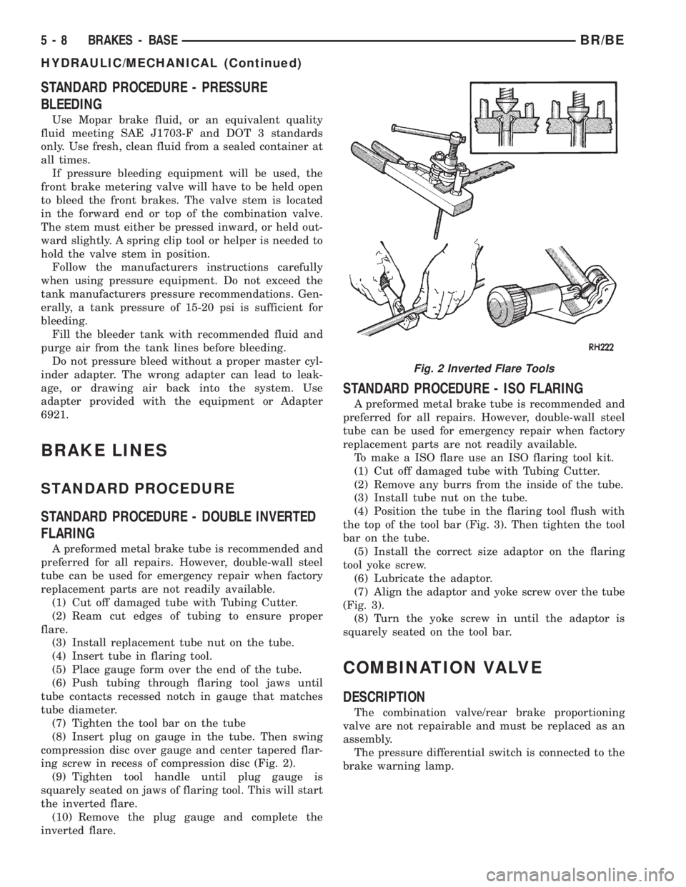
ing screw in recess of compression disc (Fig. 2).
(9) Tighten tool handle until plug gauge is
squarely seated on jaws of flaring tool. This will start
the inverted flare.
(10) Remove the plug gauge and complete the
inverted flare.
STANDARD PROCEDURE - ISO FLARING
A preformed metal brake tube is recommended and
preferred for all repairs. However, double-wall steel
tube can be used for emergency repair when factory
replacement parts are not readily available.
To make a ISO flare use an ISO flaring tool kit.
(1) Cut off damaged tube with Tubing Cutter.
(2) Remove any burrs from the inside of the tube.
(3) Install tube nut on the tube.
(4) Position the tube in the flaring tool flush with
the top of the tool bar (Fig. 3). Then tighten the tool
bar on the tube.
(5) Install the correct size adaptor on the flaring
tool yoke screw.
(6) Lubricate the adaptor.
(7) Align the adaptor and yoke screw over the tube
(Fig. 3).
(8) Turn the yoke screw in until the adaptor is
squarely seated on the tool bar.
COMBINATION VALVE
DESCRIPTION
The combination valve/rear brake proportioning
valve are not repairable and must be replaced as an
assembly.
The pressure differential switch is connected to the
brake warning lamp.
Fig. 2 Inverted Flare Tools
5 - 8 BRAKES - BASEBR/BE
HYDRAULIC/MECHANICAL (Continued)
Page 198 of 2255

OPERATION
PRESSURE DIFFERENTIAL SWITCH
The switch is triggered by movement of the switch
valve. The purpose of the switch is to monitor fluid
pressure in the separate front/rear brake hydraulic
circuits.
A decrease or loss of fluid pressure in either
hydraulic circuit will cause the switch valve to shut-
tle forward or rearward in response to the pressure
differential. Movement of the switch valve will push
the switch plunger upward. This closes the switch
internal contacts completing the electrical circuit to
the warning lamp. The switch valve may remain in
an actuated position until repair restores system
pressures to normal levels.
DIAGNOSIS AND TESTING - COMBINATION
VALVE
Pressure Differential Switch
(1) Have helper sit in drivers seat to apply brake
pedal and observe red brake warning light.
(2) Raise vehicle on hoist.(3) Connect bleed hose to a rear wheel cylinder
and immerse hose end in container partially filled
with brake fluid.
(4) Have helper press and hold brake pedal to floor
and observe warning light.
(a) If warning light illuminates, switch is operat-
ing correctly.
(b) If light fails to illuminate, check circuit fuse,
bulb, and wiring. The parking brake switch can be
used to aid in identifying whether or not the brake
light bulb and fuse is functional. Repair or replace
parts as necessary and test differential pressure
switch operation again.
(5) If warning light still does not illuminate,
switch is faulty. Replace combination valve assembly,
bleed brake system and verify proper switch and
valve operation.
REMOVAL
(1) Remove pressure differential switch wire con-
nector (Fig. 4) from the valve.
(2) Remove the brake lines from the valve.
(3) Remove the valve mounting bolt and remove
the valve from the bracket.
INSTALLATION
(1) Position the valve on the bracket and install
the mounting bolt. Tighten the mounting bolt to 23
N´m (210 in. lbs.).
(2) Install the brake lines into the valve and
tighten to 19-23 N´m (170-200 in. lbs.).
Fig. 3 ISO Flaring
1 - ADAPTER
2 - LUBRICATE HERE
3 - PILOT
4 - FLUSH WITH BAR
5 - TUBING
6 - BAR ASSEMBLY
Fig. 4 Pressure
1 - COMBINATION VALVE
2 - BRAKE LINES
3 - MOUNTING BOLT
4 - PRESSURE DIFFERENTIAL SWITCH
BR/BEBRAKES - BASE 5 - 9
COMBINATION VALVE (Continued)
Page 199 of 2255

(3) Connect the pressure differential switch wire
connector.
(4) Bleed base brake system, (Refer to 5 -
BRAKES/HYDRAULIC/MECHANICAL - STAN-
DARD PROCEDURE).
DISC BRAKE CALIPERS
DESCRIPTION
The caliper is a one-piece casting. The piston bores
are located in the inboard side. A square-cut piston
seal is located in a machined groove in the cylinder
bore.
The caliper pistons dust boot prevents dirt, water
and road splash from entering the piston bore. The
boot is seated in a groove machined at the outer end
of the caliper piston. The boot retaining flange is
seated in a counterbore machined in the outer end of
the caliper piston bore.
Ventilated disc brake rotors are used for all appli-
cations. The rotors are serviceable and can be
machined to restore surface finish when necessary.
OPERATION
When the brakes are applied fluid pressure is
exerted against the caliper piston. The fluid pressure
is exerted equally and in all directions. This means
pressure exerted against the caliper piston and
within the caliper bore will be equal (Fig. 5).
Fluid pressure applied to the piston is transmitted
directly to the inboard brake shoe. This forces the
shoe lining against the inner surface of the disc
brake rotor. At the same time, fluid pressure within
the piston bore forces the caliper to slide inward on
the mounting bolts. This action brings the outboard
brake shoe lining into contact with the outer surface
of the disc brake rotor.
In summary, fluid pressure acting simultaneously
on both piston and caliper, produces a strong clamp-
ing action. When sufficient force is applied, friction
will attempt to stop the rotors from turning and
bring the vehicle to a stop.
Application and release of the brake pedal gener-
ates only a very slight movement of the caliper and
piston. Upon release of the pedal, the caliper and pis-
ton return to a rest position. The brake shoes do not
retract an appreciable distance from the rotor. In
fact, clearance is usually at, or close to zero. The rea-
sons for this are to keep road debris from getting
between the rotor and lining and in wiping the rotor
surface clear each revolution.
The caliper piston seal controls the amount of pis-
ton extension needed to compensate for normal lining
wear.During brake application, the seal is deflected out-
ward by fluid pressure and piston movement (Fig. 6).
When the brakes (and fluid pressure) are released,
the seal relaxes and retracts the piston.
The amount of piston retraction is determined by
the amount of seal deflection. Generally the amount
is just enough to maintain contact between the pis-
ton and inboard brake shoe.
REMOVAL
REMOVAL - REAR
(1) Raise and support the vehicle.
(2) Remove the tire and wheel assembly.
(3) Compress the disc brake caliper using tool
#C4212F.
(4) Remove the caliper pin bolts.
(5) Remove the banjo bolt and discard the copper
washer.
CAUTION: Never allow the disc brake caliper to
hang from the brake hose. Damage to the brake
hose with result. Provide a suitable support to hang
the caliper securely.
(6) Remove the rear disc brake caliper (Fig. 7).
Fig. 5 Brake Caliper Operation
1 - CALIPER
2 - PISTON
3 - PISTON BORE
4 - SEAL
5 - INBOARD SHOE
6 - OUTBOARD SHOE
5 - 10 BRAKES - BASEBR/BE
COMBINATION VALVE (Continued)
Page 210 of 2255
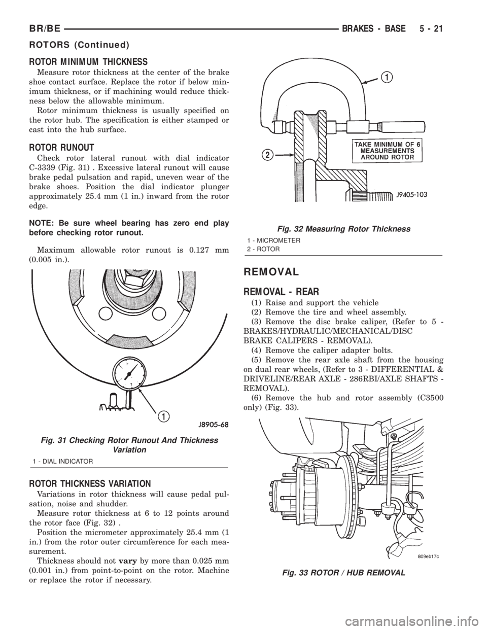
ROTOR MINIMUM THICKNESS
Measure rotor thickness at the center of the brake
shoe contact surface. Replace the rotor if below min-
imum thickness, or if machining would reduce thick-
ness below the allowable minimum.
Rotor minimum thickness is usually specified on
the rotor hub. The specification is either stamped or
cast into the hub surface.
ROTOR RUNOUT
Check rotor lateral runout with dial indicator
C-3339 (Fig. 31) . Excessive lateral runout will cause
brake pedal pulsation and rapid, uneven wear of the
brake shoes. Position the dial indicator plunger
approximately 25.4 mm (1 in.) inward from the rotor
edge.
NOTE: Be sure wheel bearing has zero end play
before checking rotor runout.
Maximum allowable rotor runout is 0.127 mm
(0.005 in.).
ROTOR THICKNESS VARIATION
Variations in rotor thickness will cause pedal pul-
sation, noise and shudder.
Measure rotor thickness at 6 to 12 points around
the rotor face (Fig. 32) .
Position the micrometer approximately 25.4 mm (1
in.) from the rotor outer circumference for each mea-
surement.
Thickness should notvaryby more than 0.025 mm
(0.001 in.) from point-to-point on the rotor. Machine
or replace the rotor if necessary.
REMOVAL
REMOVAL - REAR
(1) Raise and support the vehicle
(2) Remove the tire and wheel assembly.
(3) Remove the disc brake caliper, (Refer to 5 -
BRAKES/HYDRAULIC/MECHANICAL/DISC
BRAKE CALIPERS - REMOVAL).
(4) Remove the caliper adapter bolts.
(5) Remove the rear axle shaft from the housing
on dual rear wheels, (Refer to 3 - DIFFERENTIAL &
DRIVELINE/REAR AXLE - 286RBI/AXLE SHAFTS -
REMOVAL).
(6) Remove the hub and rotor assembly (C3500
only) (Fig. 33).
Fig. 31 Checking Rotor Runout And Thickness
Variation
1 - DIAL INDICATOR
Fig. 32 Measuring Rotor Thickness
1 - MICROMETER
2 - ROTOR
Fig. 33 ROTOR / HUB REMOVAL
BR/BEBRAKES - BASE 5 - 21
ROTORS (Continued)