Page 142 of 2255
(19) Push and hold differential case toward pinion
gear and zero the dial indicator (Fig. 17).Fig. 14 DIFFERENTIAL SIDE PLAY
1 - DIFFERENTIAL CASE
2 - DIFFERENTIAL HOUSING
3 - PILOT STUD
4 - DIAL INDICATOR
Fig. 15 DIAL INDICATOR LOCATION
1 - DIFFERENTIAL CASE TO PINION GEAR SIDE
2 - PILOT STUD
3 - DIAL INDICATOR ARM
4 - DIAL INDICATOR FACE
Fig. 16 DIFFERENTIAL CASE RING GEAR SIDE
1 - DIAL INDICATOR
2 - DIFFERENTIAL CASE TO RING GEAR SIDE
3 - DIFFERENTIAL HOUSING
Fig. 17 DIFFERENTIAL CASE PINION GEAR SIDE
1 - DIAL INDICATOR FACE
2 - DIFFERENTIAL CASE TO PINION GEAR SIDE
3 - PINION GEAR
4 - DIFFERENTIAL HOUSING
5 - DIFFERENTIAL CASE
BR/BEREAR AXLE - 267RBI 3 - 87
REAR AXLE - 267RBI (Continued)
Page 143 of 2255
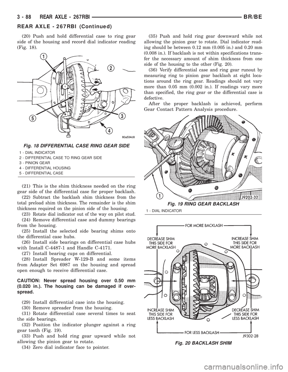
(20) Push and hold differential case to ring gear
side of the housing and record dial indicator reading
(Fig. 18).
(21) This is the shim thickness needed on the ring
gear side of the differential case for proper backlash.
(22)
Subtract the backlash shim thickness from the
total preload shim thickness. The remainder is the shim
thickness required on the pinion side of the housing.
(23)Rotate dial indicator out of the way on pilot stud.
(24) Remove differential case and dummy bearings
from the housing.
(25) Install the selected side bearing shims onto
the differential case hubs.
(26) Install side bearings on differential case hubs
with Install C-4487-1 and Handle C-4171.
(27) Install bearing cups on differential.
(28) Install Spreader W-129-B and some items
from Adapter Set 6987 on the housing and spread
open enough to receive differential case.
CAUTION: Never spread housing over 0.50 mm
(0.020 in.). The housing can be damaged if over-
spread.
(29) Install differential case into the housing.
(30) Remove spreader from the housing.
(31) Rotate differential case several times to seat
the side bearings.
(32) Position the indicator plunger against a ring
gear tooth (Fig. 19).
(33) Push and hold ring gear upward while not
allowing the pinion gear to rotate.
(34) Zero dial indicator face to pointer.(35)
Push and hold ring gear downward while not
allowing the pinion gear to rotate. Dial indicator read-
ing should be between 0.12 mm (0.005 in.) and 0.20 mm
(0.008 in.). If backlash is not within specifications trans-
fer the necessary amount of shim thickness from one
side of the housing to the other (Fig. 20).
(36)Verify differential case and ring gear runout by
measuring ring to pinion gear backlash at eight loca-
tions around the ring gear. Readings should not vary
more than 0.05 mm (0.002 in.). If readings vary more
than specified, the ring gear or the differential case is
defective.
After the proper backlash is achieved, perform
Gear Contact Pattern Analysis procedure.
Fig. 18 DIFFERENTIAL CASE RING GEAR SIDE
1 - DIAL INDICATOR
2 - DIFFERENTIAL CASE TO RING GEAR SIDE
3 - PINION GEAR
4 - DIFFERENTIAL HOUSING
5 - DIFFERENTIAL CASE
Fig. 19 RING GEAR BACKLASH
1 - DIAL INDICATOR
Fig. 20 BACKLASH SHIM
3 - 88 REAR AXLE - 267RBIBR/BE
REAR AXLE - 267RBI (Continued)
Page 144 of 2255
GEAR CONTACT PATTERN
The ring and pinion gear contact patterns will
show if the pinion depth is correct. It will also show
if the ring gear backlash has been adjusted correctly.
The backlash can be adjusted within specifications to
achieve desired tooth contact patterns.
(1) Apply a thin coat of hydrated ferric oxide or
equivalent to the drive and coast side of the ring gear
teeth.
(2) Wrap, twist and hold a shop towel around the
pinion yoke to increase the turning resistance of the
pinion. This will provide a more distinct contact pat-
tern.(3) With a boxed end wrench on the ring gear bolt,
rotate the differential case one complete revolution in
both directions while a load is being applied from
shop towel.
The areas on the ring gear teeth with the greatest
degree of contact against the pinion teeth will squee-
gee the compound to the areas with the least amount
of contact. Note and compare patterns on the ring
gear teeth to Gear Tooth Contact Patterns chart (Fig.
21)and adjust pinion depth and gear backlash as nec-
essary.
BR/BEREAR AXLE - 267RBI 3 - 89
REAR AXLE - 267RBI (Continued)
Page 146 of 2255
SPECIFICATIONS
REAR AXLE - 267RBI
AXLE SPECIFICATIONS
DESCRIPTION SPECIFICATION
Axle Ratio 3.55, 4.10
Ring Gear Diameter 267 mm (10.50 in.)
Ring Gear Backlash 0.12-0.20 mm (0.005-0.008 in.)
Pinion Gear Standard. Depth 136.53 mm (5.375 in.)
Pinion Bearing Preload - Original Bearings 1-2 N´m (10-20 in. lbs.)
Pinion Bearing Preload - New Bearings 2.3-5.1 N´m (20-45 in. lbs.)
TORQUE SPECIFICATIONS
DESCRIPTION N´m Ft. Lbs. In. Lbs.
Fill Hole Plug 34 25 -
Differential Cover Bolts 47 35 -
Bearing Cap Bolts 108 80 -
Ring Gear Bolt 176 130 -
Pinion Nut 298-380 220-280 -
Axle Shaft Bolts 129 95 -
Hub Bearing Nut 163-190 120-140 -
SPECIAL TOOLS
REAR AXLE - 267RBI
Puller 6790
Wrench DD-1241-JD
Installer 5064
Installer 8149
BR/BEREAR AXLE - 267RBI 3 - 91
REAR AXLE - 267RBI (Continued)
Page 150 of 2255
(8) Hold yoke with Yoke Holder 6719A and remove
the pinion shaft nut and washer.
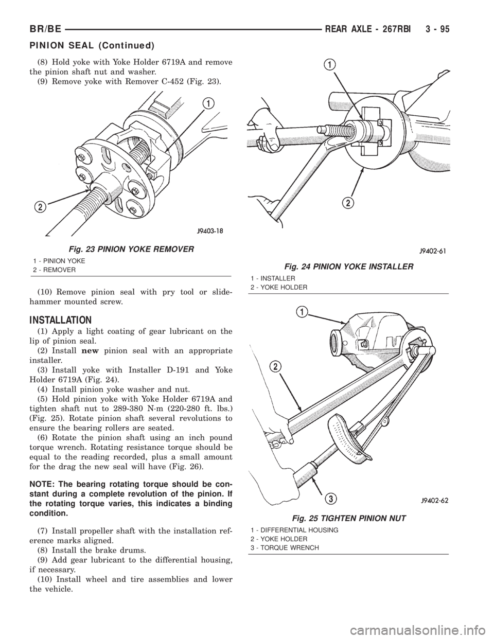
(9) Remove yoke with Remover C-452 (Fig. 23).
(10) Remove pinion seal with pry tool or slide-
hammer mounted screw.
INSTALLATION
(1) Apply a light coating of gear lubricant on the
lip of pinion seal.
(2) Installnewpinion seal with an appropriate
installer.
(3) Install yoke with Installer D-191 and Yoke
Holder 6719A (Fig. 24).
(4) Install pinion yoke washer and nut.
(5) Hold pinion yoke with Yoke Holder 6719A and
tighten shaft nut to 289-380 N´m (220-280 ft. lbs.)
(Fig. 25). Rotate pinion shaft several revolutions to
ensure the bearing rollers are seated.
(6) Rotate the pinion shaft using an inch pound
torque wrench. Rotating resistance torque should be
equal to the reading recorded, plus a small amount
for the drag the new seal will have (Fig. 26).
NOTE: The bearing rotating torque should be con-
stant during a complete revolution of the pinion. If
the rotating torque varies, this indicates a binding
condition.
(7) Install propeller shaft with the installation ref-
erence marks aligned.
(8) Install the brake drums.
(9) Add gear lubricant to the differential housing,
if necessary.
(10) Install wheel and tire assemblies and lower
the vehicle.
Fig. 23 PINION YOKE REMOVER
1 - PINION YOKE
2 - REMOVERFig. 24 PINION YOKE INSTALLER
1 - INSTALLER
2 - YOKE HOLDER
Fig. 25 TIGHTEN PINION NUT
1 - DIFFERENTIAL HOUSING
2 - YOKE HOLDER
3 - TORQUE WRENCH
BR/BEREAR AXLE - 267RBI 3 - 95
PINION SEAL (Continued)
Page 151 of 2255
DIFFERENTIAL
REMOVAL
(1) Raise and support the vehicle.
(2) Remove fill hole plug from the differential
housing cover.
(3) Remove differential housing cover and drain
lubricant from the housing.
(4) Clean the housing cavity with a flushing oil,
light engine oil or lint free cloth.Do not use water,
steam, kerosene or gasoline for cleaning.
(5) Remove axle shafts.
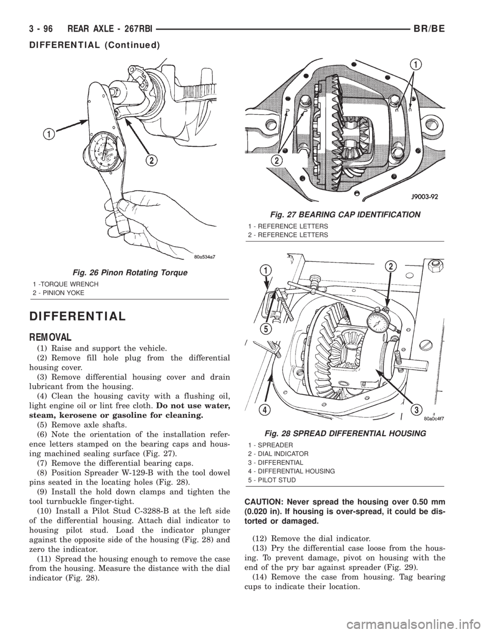
(6) Note the orientation of the installation refer-
ence letters stamped on the bearing caps and hous-
ing machined sealing surface (Fig. 27).
(7) Remove the differential bearing caps.
(8) Position Spreader W-129-B with the tool dowel
pins seated in the locating holes (Fig. 28).
(9) Install the hold down clamps and tighten the
tool turnbuckle finger-tight.
(10) Install a Pilot Stud C-3288-B at the left side
of the differential housing. Attach dial indicator to
housing pilot stud. Load the indicator plunger
against the opposite side of the housing (Fig. 28) and
zero the indicator.
(11) Spread the housing enough to remove the case
from the housing. Measure the distance with the dial
indicator (Fig. 28).CAUTION: Never spread the housing over 0.50 mm
(0.020 in). If housing is over-spread, it could be dis-
torted or damaged.
(12) Remove the dial indicator.
(13) Pry the differential case loose from the hous-
ing. To prevent damage, pivot on housing with the
end of the pry bar against spreader (Fig. 29).
(14) Remove the case from housing. Tag bearing
cups to indicate their location.
Fig. 26 Pinon Rotating Torque
1 -TORQUE WRENCH
2 - PINION YOKE
Fig. 27 BEARING CAP IDENTIFICATION
1 - REFERENCE LETTERS
2 - REFERENCE LETTERS
Fig. 28 SPREAD DIFFERENTIAL HOUSING
1 - SPREADER
2 - DIAL INDICATOR
3 - DIFFERENTIAL
4 - DIFFERENTIAL HOUSING
5 - PILOT STUD
3 - 96 REAR AXLE - 267RBIBR/BE
DIFFERENTIAL (Continued)
Page 152 of 2255
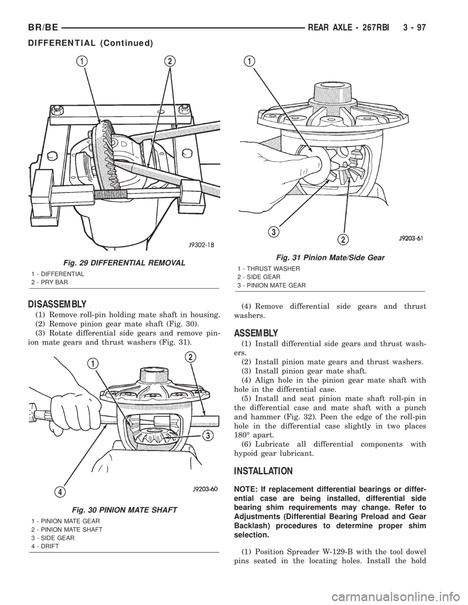
DISASSEMBLY
(1) Remove roll-pin holding mate shaft in housing.
(2) Remove pinion gear mate shaft (Fig. 30).
(3) Rotate differential side gears and remove pin-
ion mate gears and thrust washers (Fig. 31).(4) Remove differential side gears and thrust
washers.
ASSEMBLY
(1) Install differential side gears and thrust wash-
ers.
(2) Install pinion mate gears and thrust washers.
(3) Install pinion gear mate shaft.
(4) Align hole in the pinion gear mate shaft with
hole in the differential case.
(5) Install and seat pinion mate shaft roll-pin in
the differential case and mate shaft with a punch
and hammer (Fig. 32). Peen the edge of the roll-pin
hole in the differential case slightly in two places
180É apart.
(6) Lubricate all differential components with
hypoid gear lubricant.
INSTALLATION
NOTE: If replacement differential bearings or differ-
ential case are being installed, differential side
bearing shim requirements may change. Refer to
Adjustments (Differential Bearing Preload and Gear
Backlash) procedures to determine proper shim
selection.
(1) Position Spreader W-129-B with the tool dowel
pins seated in the locating holes. Install the hold
Fig. 29 DIFFERENTIAL REMOVAL
1 - DIFFERENTIAL
2-PRYBAR
Fig. 30 PINION MATE SHAFT
1 - PINION MATE GEAR
2 - PINION MATE SHAFT
3 - SIDE GEAR
4 - DRIFT
Fig. 31 Pinion Mate/Side Gear
1 - THRUST WASHER
2 - SIDE GEAR
3 - PINION MATE GEAR
BR/BEREAR AXLE - 267RBI 3 - 97
DIFFERENTIAL (Continued)
Page 153 of 2255

down clamps and tighten the tool turnbuckle finger-
tight.
(2) Install a Pilot Stud C-3288-B at the left side of
the differential housing and attach dial indicator to
the pilot stud. Load the indicator plunger against the
opposite side of the housing and zero the dial indica-
tor.
(3) Spread the housing enough to install the case
in the housing. Measure the distance with the dial
indicator.
CAUTION: Do not spread over 0.50 mm (0.020 in). If
the housing is over-spread, it could be distorted or
damaged.
(4) Remove the dial indicator.
(5) Install differential into the housing. Tap the
differential case with a rawhide/rubber hammer to
ensure the bearings are seated in housing (Fig. 33).
(6) Remove the spreader.
(7) Install bearing caps in their original locations
(Fig. 34) and tighten bearing cap bolts in a criss-
cross pattern to 109 N´m (80 ft. lbs.).
(8) Install axle shafts.
(9) Install the hub bearings.
(10) Apply a bead of red Mopar Silicone Rubber
Sealant or equivalent to the housing cover (Fig. 35).CAUTION: If housing cover is not installed within 3
to 5 minutes, the cover must be cleaned and new
RTV applied or adhesion quality will be compro-
mised.
(11) Install the cover and any identification tag.
Tighten the cover bolts in a criss-cross pattern to 47
N´m (35 ft. lbs.).
(12) Fill the differential with Mopar Hypoid Gear
Lubricant or equivalent to bottom of the fill plug
hole.
Fig. 32 Pinion Mate Shaft Roll-Pin
1 - PUNCH
2 - PINION MATE SHAFT
3 - MATE SHAFT LOCKPIN
Fig. 33 DIFFERENTIAL CASE
1 - RAWHIDE HAMMER
Fig. 34 BEARING CAP IDENTIFICATION
1 - REFERENCE LETTERS
2 - REFERENCE LETTERS
3 - 98 REAR AXLE - 267RBIBR/BE
DIFFERENTIAL (Continued)