2002 DODGE RAM differential
[x] Cancel search: differentialPage 172 of 2255
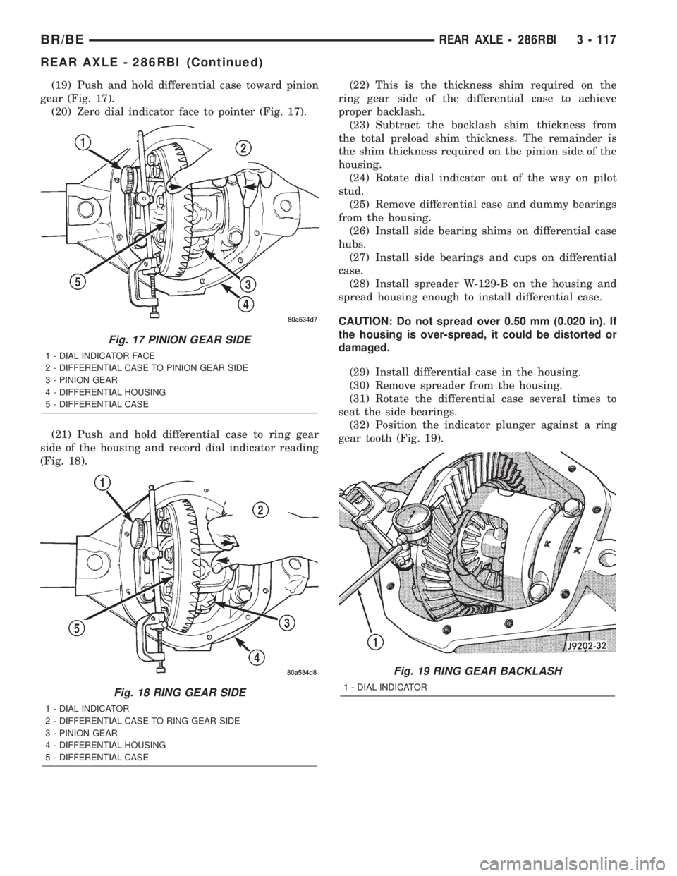
(19) Push and hold differential case toward pinion
gear (Fig. 17).
(20) Zero dial indicator face to pointer (Fig. 17).
(21) Push and hold differential case to ring gear
side of the housing and record dial indicator reading
(Fig. 18).(22) This is the thickness shim required on the
ring gear side of the differential case to achieve
proper backlash.
(23) Subtract the backlash shim thickness from
the total preload shim thickness. The remainder is
the shim thickness required on the pinion side of the
housing.
(24) Rotate dial indicator out of the way on pilot
stud.
(25) Remove differential case and dummy bearings
from the housing.
(26) Install side bearing shims on differential case
hubs.
(27) Install side bearings and cups on differential
case.
(28) Install spreader W-129-B on the housing and
spread housing enough to install differential case.
CAUTION: Do not spread over 0.50 mm (0.020 in). If
the housing is over-spread, it could be distorted or
damaged.
(29) Install differential case in the housing.
(30) Remove spreader from the housing.
(31) Rotate the differential case several times to
seat the side bearings.
(32) Position the indicator plunger against a ring
gear tooth (Fig. 19).
Fig. 17 PINION GEAR SIDE
1 - DIAL INDICATOR FACE
2 - DIFFERENTIAL CASE TO PINION GEAR SIDE
3 - PINION GEAR
4 - DIFFERENTIAL HOUSING
5 - DIFFERENTIAL CASE
Fig. 18 RING GEAR SIDE
1 - DIAL INDICATOR
2 - DIFFERENTIAL CASE TO RING GEAR SIDE
3 - PINION GEAR
4 - DIFFERENTIAL HOUSING
5 - DIFFERENTIAL CASE
Fig. 19 RING GEAR BACKLASH
1 - DIAL INDICATOR
BR/BEREAR AXLE - 286RBI 3 - 117
REAR AXLE - 286RBI (Continued)
Page 173 of 2255
(33) Push and hold ring gear upward while not
allowing the pinion gear to rotate.
(34) Zero dial indicator face to pointer.
(35) Push and hold ring gear downward while not
allowing the pinion gear to rotate. Dial indicator
reading should be between 0.12 mm (0.005 in.) and
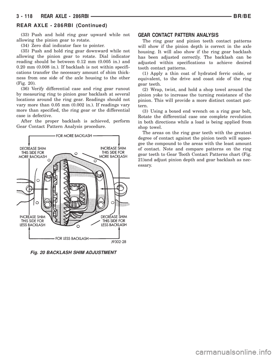
0.20 mm (0.008 in.). If backlash is not within specifi-
cations transfer the necessary amount of shim thick-
ness from one side of the axle housing to the other
(Fig. 20).
(36) Verify differential case and ring gear runout
by measuring ring to pinion gear backlash at several
locations around the ring gear. Readings should not
vary more than 0.05 mm (0.002 in.). If readings vary
more than specified, the ring gear or the differential
case is defective.
After the proper backlash is achieved, perform
Gear Contact Pattern Analysis procedure.GEAR CONTACT PATTERN ANALYSIS
The ring gear and pinion teeth contact patterns
will show if the pinion depth is correct in the axle
housing. It will also show if the ring gear backlash
has been adjusted correctly. The backlash can be
adjusted within specifications to achieve desired
tooth contact patterns.
(1) Apply a thin coat of hydrated ferric oxide, or
equivalent, to the drive and coast side of the ring
gear teeth.
(2) Wrap, twist, and hold a shop towel around the
pinion yoke to increase the turning resistance of the
pinion. This will provide a more distinct contact pat-
tern.
(3) Using a boxed end wrench on a ring gear bolt,
Rotate the differential case one complete revolution
in both directions while a load is being applied from
shop towel.
The areas on the ring gear teeth with the greatest
degree of contact against the pinion teeth will squee-
gee the compound to the areas with the least amount
of contact. Note and compare patterns on the ring
gear teeth to Gear Tooth Contact Patterns chart (Fig.
21)and adjust pinion depth and gear backlash as nec-
essary.
Fig. 20 BACKLASH SHIM ADJUSTMENT
3 - 118 REAR AXLE - 286RBIBR/BE
REAR AXLE - 286RBI (Continued)
Page 175 of 2255
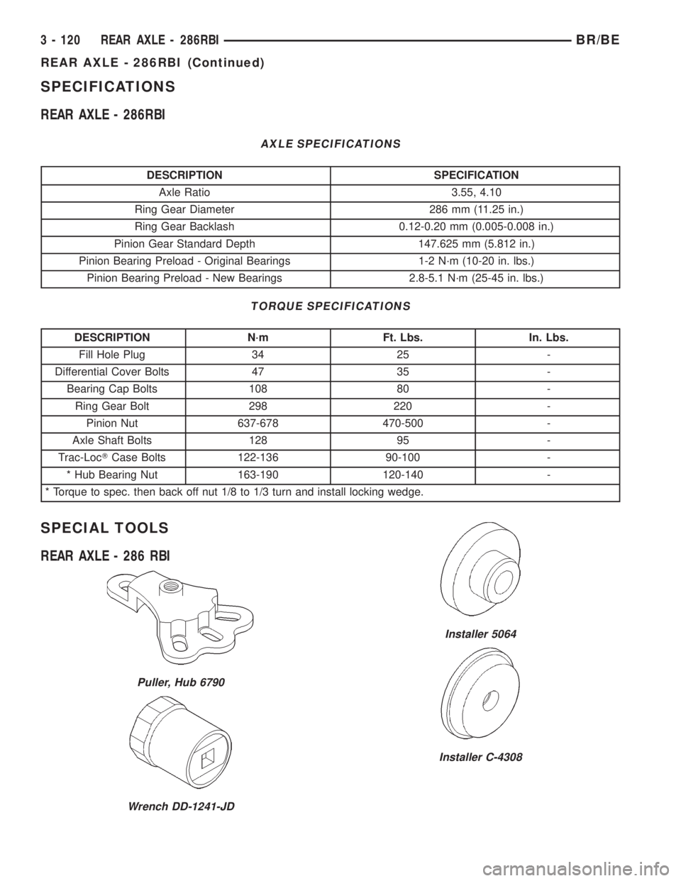
SPECIFICATIONS
REAR AXLE - 286RBI
AXLE SPECIFICATIONS
DESCRIPTION SPECIFICATION
Axle Ratio 3.55, 4.10
Ring Gear Diameter 286 mm (11.25 in.)
Ring Gear Backlash 0.12-0.20 mm (0.005-0.008 in.)
Pinion Gear Standard Depth 147.625 mm (5.812 in.)
Pinion Bearing Preload - Original Bearings 1-2 N´m (10-20 in. lbs.)
Pinion Bearing Preload - New Bearings 2.8-5.1 N´m (25-45 in. lbs.)
TORQUE SPECIFICATIONS
DESCRIPTION N´m Ft. Lbs. In. Lbs.
Fill Hole Plug 34 25 -
Differential Cover Bolts 47 35 -
Bearing Cap Bolts 108 80 -
Ring Gear Bolt 298 220 -
Pinion Nut 637-678 470-500 -
Axle Shaft Bolts 128 95 -
Trac-LocTCase Bolts 122-136 90-100 -
* Hub Bearing Nut 163-190 120-140 -
* Torque to spec. then back off nut 1/8 to 1/3 turn and install locking wedge.
SPECIAL TOOLS
REAR AXLE - 286 RBI
Puller, Hub 6790
Wrench DD-1241-JD
Installer 5064
Installer C-4308
3 - 120 REAR AXLE - 286RBIBR/BE
REAR AXLE - 286RBI (Continued)
Page 179 of 2255
INSTALLATION
(1) Clean the seal contact surface in the housing
bore.
(2) Apply a light coating of gear lubricant on the
lip of pinion seal.
(3) Installnewpinion shaft seal with an appropri-
ate Installer.
(4) Position pinion yoke on the end of the shaft
with the reference marks aligned.
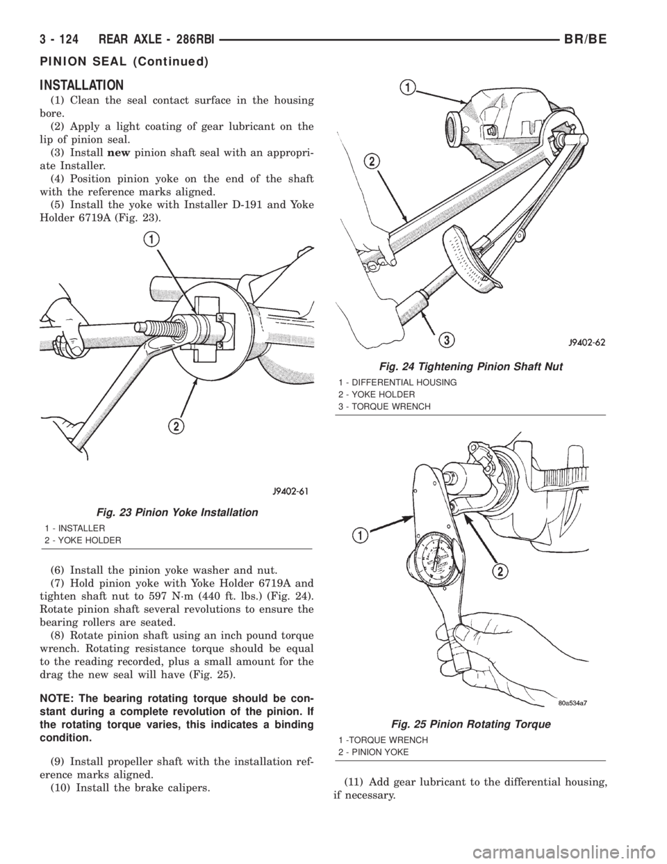
(5) Install the yoke with Installer D-191 and Yoke
Holder 6719A (Fig. 23).
(6) Install the pinion yoke washer and nut.
(7) Hold pinion yoke with Yoke Holder 6719A and
tighten shaft nut to 597 N´m (440 ft. lbs.) (Fig. 24).
Rotate pinion shaft several revolutions to ensure the
bearing rollers are seated.
(8) Rotate pinion shaft using an inch pound torque
wrench. Rotating resistance torque should be equal
to the reading recorded, plus a small amount for the
drag the new seal will have (Fig. 25).
NOTE: The bearing rotating torque should be con-
stant during a complete revolution of the pinion. If
the rotating torque varies, this indicates a binding
condition.
(9) Install propeller shaft with the installation ref-
erence marks aligned.
(10) Install the brake calipers.(11) Add gear lubricant to the differential housing,
if necessary.
Fig. 23 Pinion Yoke Installation
1 - INSTALLER
2 - YOKE HOLDER
Fig. 24 Tightening Pinion Shaft Nut
1 - DIFFERENTIAL HOUSING
2 - YOKE HOLDER
3 - TORQUE WRENCH
Fig. 25 Pinion Rotating Torque
1 -TORQUE WRENCH
2 - PINION YOKE
3 - 124 REAR AXLE - 286RBIBR/BE
PINION SEAL (Continued)
Page 180 of 2255
(12) Install wheel and tire assemblies and lower
the vehicle.
DIFFERENTIAL
REMOVAL
(1) Raise and support the vehicle.
(2) Remove fill hole plug from the differential
housing cover.
(3) Remove differential housing cover and drain
lubricant from the housing.
(4) Clean the housing cavity with a flushing oil,
light engine oil or lint free cloth.Do not use water,
steam, kerosene or gasoline for cleaning.
(5) Remove axle shafts.
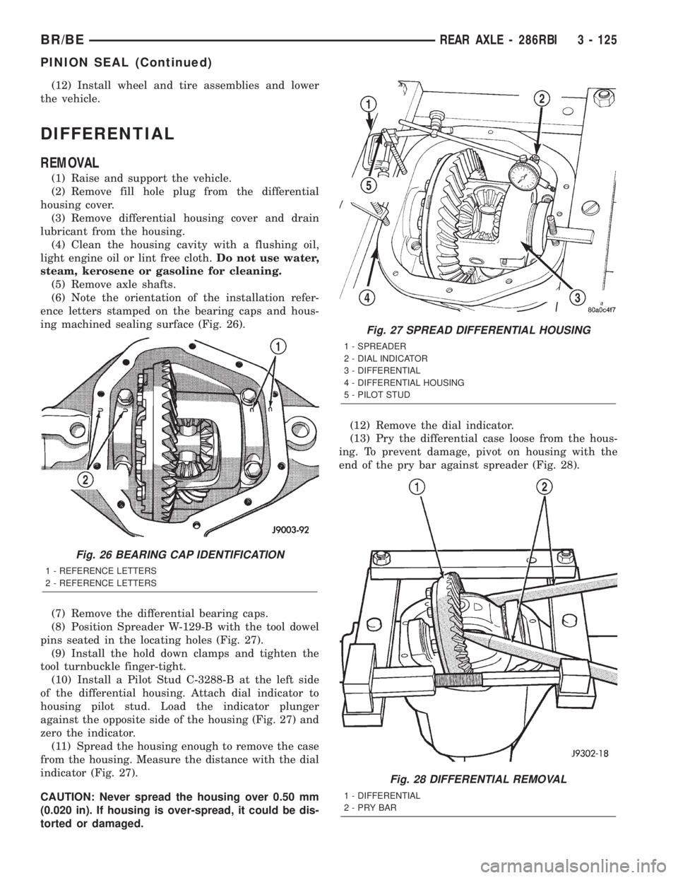
(6) Note the orientation of the installation refer-
ence letters stamped on the bearing caps and hous-
ing machined sealing surface (Fig. 26).
(7) Remove the differential bearing caps.
(8) Position Spreader W-129-B with the tool dowel
pins seated in the locating holes (Fig. 27).
(9) Install the hold down clamps and tighten the
tool turnbuckle finger-tight.
(10) Install a Pilot Stud C-3288-B at the left side
of the differential housing. Attach dial indicator to
housing pilot stud. Load the indicator plunger
against the opposite side of the housing (Fig. 27) and
zero the indicator.
(11) Spread the housing enough to remove the case
from the housing. Measure the distance with the dial
indicator (Fig. 27).
CAUTION: Never spread the housing over 0.50 mm
(0.020 in). If housing is over-spread, it could be dis-
torted or damaged.(12) Remove the dial indicator.
(13) Pry the differential case loose from the hous-
ing. To prevent damage, pivot on housing with the
end of the pry bar against spreader (Fig. 28).
Fig. 26 BEARING CAP IDENTIFICATION
1 - REFERENCE LETTERS
2 - REFERENCE LETTERS
Fig. 27 SPREAD DIFFERENTIAL HOUSING
1 - SPREADER
2 - DIAL INDICATOR
3 - DIFFERENTIAL
4 - DIFFERENTIAL HOUSING
5 - PILOT STUD
Fig. 28 DIFFERENTIAL REMOVAL
1 - DIFFERENTIAL
2-PRYBAR
BR/BEREAR AXLE - 286RBI 3 - 125
PINION SEAL (Continued)
Page 181 of 2255
(14) Remove the case from housing. Tag bearing
cups to indicate their location.
DISASSEMBLY
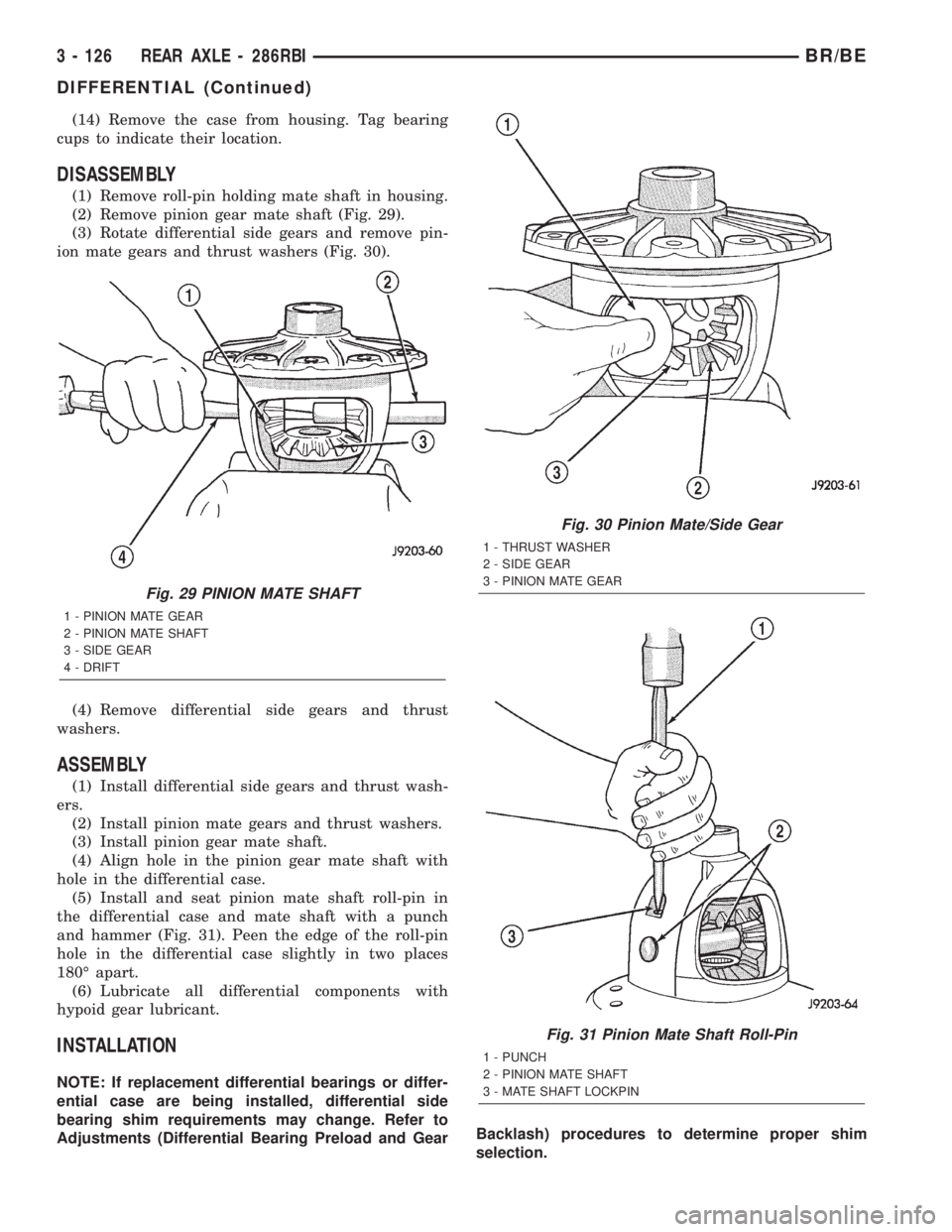
(1) Remove roll-pin holding mate shaft in housing.
(2) Remove pinion gear mate shaft (Fig. 29).
(3) Rotate differential side gears and remove pin-
ion mate gears and thrust washers (Fig. 30).
(4) Remove differential side gears and thrust
washers.
ASSEMBLY
(1) Install differential side gears and thrust wash-
ers.
(2) Install pinion mate gears and thrust washers.
(3) Install pinion gear mate shaft.
(4) Align hole in the pinion gear mate shaft with
hole in the differential case.
(5) Install and seat pinion mate shaft roll-pin in
the differential case and mate shaft with a punch
and hammer (Fig. 31). Peen the edge of the roll-pin
hole in the differential case slightly in two places
180É apart.
(6) Lubricate all differential components with
hypoid gear lubricant.
INSTALLATION
NOTE: If replacement differential bearings or differ-
ential case are being installed, differential side
bearing shim requirements may change. Refer to
Adjustments (Differential Bearing Preload and GearBacklash) procedures to determine proper shim
selection.
Fig. 29 PINION MATE SHAFT
1 - PINION MATE GEAR
2 - PINION MATE SHAFT
3 - SIDE GEAR
4 - DRIFT
Fig. 30 Pinion Mate/Side Gear
1 - THRUST WASHER
2 - SIDE GEAR
3 - PINION MATE GEAR
Fig. 31 Pinion Mate Shaft Roll-Pin
1 - PUNCH
2 - PINION MATE SHAFT
3 - MATE SHAFT LOCKPIN
3 - 126 REAR AXLE - 286RBIBR/BE
DIFFERENTIAL (Continued)
Page 182 of 2255

(1) Position Spreader W-129-B with the tool dowel
pins seated in the locating holes. Install the hold
down clamps and tighten the tool turnbuckle finger-
tight.
(2) Install a Pilot Stud C-3288-B at the left side of
the differential housing and attach dial indicator to
the pilot stud. Load the indicator plunger against the
opposite side of the housing and zero the dial indica-
tor.
(3) Spread the housing enough to install the case
in the housing. Measure the distance with the dial
indicator.
CAUTION: Never spread the housing over 0.50 mm
(0.020 in). If housing is over-spread, it could be dis-
torted or damaged.
(4) Remove the dial indicator.
(5) Install differential into the housing. Tap the
differential case with a rawhide/rubber hammer to
ensure the bearings are seated in housing (Fig. 32).
(6) Remove the spreader.
(7) Install bearing caps in their original locations
(Fig. 33) and tighten bearing cap bolts in a criss-
cross pattern to 109 N´m (80 ft. lbs.).
(8) Install axle shafts.
(9) Install the hub bearings.
(10) Apply a bead of red Mopar Silicone Rubber
Sealant or equivalent to the housing cover (Fig. 34).CAUTION: If housing cover is not installed within 3
to 5 minutes, the cover must be cleaned and new
RTV applied or adhesion quality will be compro-
mised.
(11) Install the cover and tighten bolts in a criss-
cross pattern to 47 N´m (35 ft. lbs.).
Fig. 32 DIFFERENTIAL CASE
1 - RAWHIDE HAMMER
Fig. 33 Bearing Cap Reference
1 - REFERENCE LETTERS
2 - REFERENCE LETTERS
Fig. 34 DIFFERENTIAL COVER - TYPICAL
1 - SEALANT SURFACE
2 - SEALANT
3 - SEALANT THICKNESS
BR/BEREAR AXLE - 286RBI 3 - 127
DIFFERENTIAL (Continued)
Page 183 of 2255
(12) Fill the differential with Mopar Hypoid Gear
Lubricant or equivalent to bottom of the fill plug
hole.
(13) Install fill hole plug and tighten to 34 N´m (25
ft. lbs.).
(14) Remove support and lower vehicle.
DIFFERENTIAL - TRAC-LOK
DIAGNOSIS AND TESTING - TRAC-LOKT
The most common problem is a chatter noise when
turning corners. Before removing a Trac-lokŸ unit
for repair, drain, flush and refill the axle with the
specified lubricant. A container of Mopar Trac-lokŸ
Lubricant (friction modifier) should be added after
repair service or during a lubricant change.
After changing the lubricant, drive the vehicle and
make 10 to 12 slow, figure-eight turns. This maneu-
ver will pump lubricant through the clutches. This
will correct the condition in most instances. If the
chatter persists, clutch damage could have occurred.
DIFFERENTIAL TEST
The differential can be tested without removing the
differential case by measuring rotating torque. Make
sure brakes are not dragging during this measure-
ment.
(1) Place blocks in front and rear of both front
wheels.
(2) Raise one rear wheel until it is completely off
the ground.
(3) Engine off, transmission in neutral, and park-
ing brake off.
(4) Remove wheel and bolt Special Tool 6790 or
equivalent tool to studs.
(5) Use torque wrench on special tool to rotate
wheel and read rotating torque.
(6) If rotating torque is less than 22 N´m (30 ft.
lbs.) or more than 271 N´m (200 ft. lbs.) on either
wheel the unit should be serviced.
DISASSEMBLY
The Trac-Loktdifferential on this axle has a one-
piece cross shaft and uses one dished disc, regular 5
disc and 7 plates.
NOTE: Pay attention to the clutch pack arrangement
during disassembly. Note the direction of the con-
cave and convex side of the plates and discs.
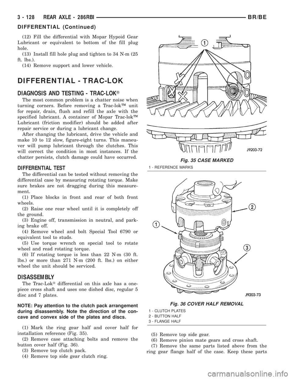
(1) Mark the ring gear half and cover half for
installation reference (Fig. 35).
(2) Remove case attaching bolts and remove the
button cover half (Fig. 36).
(3) Remove top clutch pack.
(4) Remove top side gear clutch ring.(5) Remove top side gear.
(6) Remove pinion mate gears and cross shaft.
(7) Remove the same parts listed above from the
ring gear flange half of the case. Keep these parts
Fig. 35 CASE MARKED
1 - REFERENCE MARKS
Fig. 36 COVER HALF REMOVAL
1 - CLUTCH PLATES
2 - BUTTON HALF
3 - FLANGE HALF
3 - 128 REAR AXLE - 286RBIBR/BE
DIFFERENTIAL (Continued)