Page 707 of 4323
D14154
Component Side:
A19288
± DIAGNOSTICSENGINE
DI±505
699 Author�: Date�:
2005 SEQUOIA (RM1146U)
4 Check park/neutral position switch.
PREPARATION:
Remove the P1 park/neutral position switch connector.
CHECK:
Check resistance between each terminal shown below when
the shift lever is moved to each range.
Shift rangeTerminal No. to continuity
P1 ± 36 ± 9
R2 ± 3±
N3 ± 56 ± 9
D3 ± 7±
23 ± 4±
L3 ± 8±
OK:
Below 1 W
NG Replace the park/neutral position switch.
OK
Check and repair harness and connector be-
tween park/neutral position switch and ECM.
5 Check starter relay.
(a) Remove the starter relay from the engine room R/B.
(b) Inspect the starter relay.
Standard:
Tester ConnectionSpecified Condition
3 ± 510 kW or higher
3 ± 5Below 1 W
(Apply battery voltage to terminals 1 and 2)
NG Replace starter relay.
OK
Page 708 of 4323

6 Check for open a")
A23563
Wire Harness Side
Park/Neutral position switch ConnectorN1
A21559
Engine Room R/B No.2
Starter Relay
DI±506
± DIAGNOSTICSENGINE
700 Author�: Date�:
2005 SEQUOIA (RM1146U)
6 Check for open and short in harness and connector between park/neutral posi-
tion switch and starter relay.
(a) Check the harness and the connector between the park/
neutral position switch connector and the starter relay.
(1) Disconnect the park/neutral position switch con-
nector.
(2) Remove the starter relay from the engine room R/B.
(3) Check for resistance between the wire harness side
connectors.
Standard (Check for open):
Symbols (Terminal No.)Specified condition
Park/Neutral position switch (N1±6) ± Starter relay (1)Below 1 W
Standard (Check for short):
Symbols (Terminal No.)Specified condition
Park/Neutral position switch (N1±6) or Starter relay (1)
± Body ground10 kW or higher
(b) Check the harness and the connector between the starter
relay and the body ground.
(1) Remove the starter relay from the engine room R/B.
(2) Check for resistance between the starter relay and
the body ground.
Standard (Check for open):
Symbols (Terminal No.)Specified condition
Starter relay (2) ± Body groundBelow 1 W
NG Repair or replace harness or connector.
OK
Page 709 of 4323
A21559
Engine Room R/B No.2
Starter Relay
± DIAGNOSTICSENGINE
DI±507
701 Author�: Date�:
2005 SEQUOIA (RM1146U)
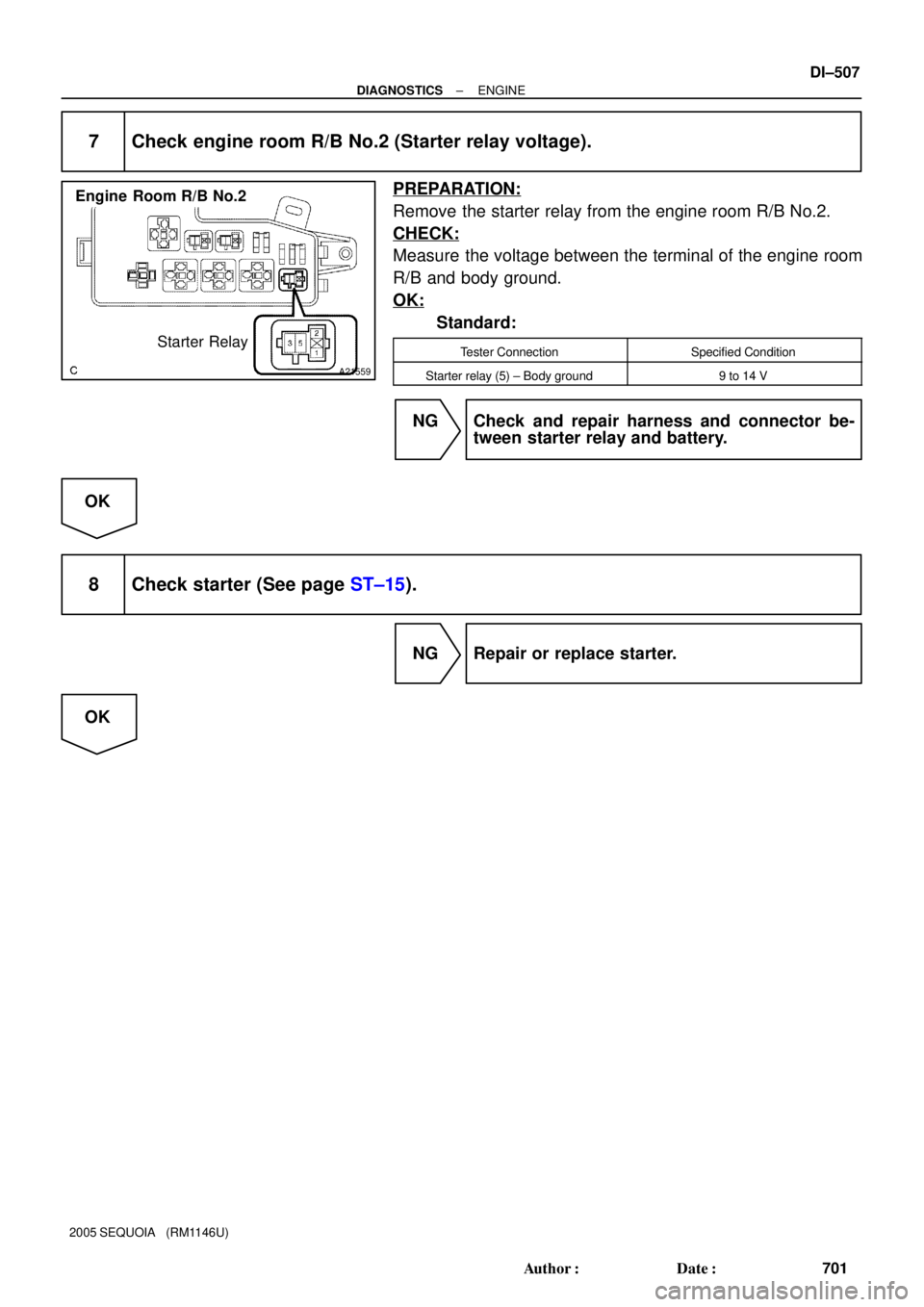
7 Check engine room R/B No.2 (Starter relay voltage).
PREPARATION:
Remove the starter relay from the engine room R/B No.2.
CHECK:
Measure the voltage between the terminal of the engine room
R/B and body ground.
OK:
Standard:
Tester ConnectionSpecified Condition
Starter relay (5) ± Body ground9 to 14 V
NG Check and repair harness and connector be-
tween starter relay and battery.
OK
8 Check starter (See page ST±15).
NG Repair or replace starter.
OK
Page 711 of 4323
± DIAGNOSTICSENGINE
DI±509
703 Author�: Date�:
2005 SEQUOIA (RM1146U)
Fuel Pump Control Circuit
CIRCUIT DESCRIPTION
Refer to DTC P0230 on page DI±179.
WIRING DIAGRAM
Refer to DTC P0230 on page DI±179.
INSPECTION PROCEDURE
1 Check fuel pump operation (See page SF±7).
OK Go to step 8.
NG
2 Connect hand±held tester, and check operation of fuel pump relay.
PREPARATION:
(a) Connect the hand±held tester to the DLC3.
(b) Turn the ignition switch ON and push the hand±held tester main switch ON.
(c) Enter the following menu: DIAGNOSIS / ENHANCED OBD II / ACTIVE TEST / FUEL PUMP SPD.
CHECK:
Check the operation of the fuel pump relay when it is switched ON and OFF by the hand±held tester.
OK:
Operating noise can be heard from the relay.
OK Go to step 4.
NG
DID8L±01
Page 712 of 4323
A21024
A19288
DI±510
± DIAGNOSTICSENGINE
704 Author�: Date�:
2005 SEQUOIA (RM1146U)
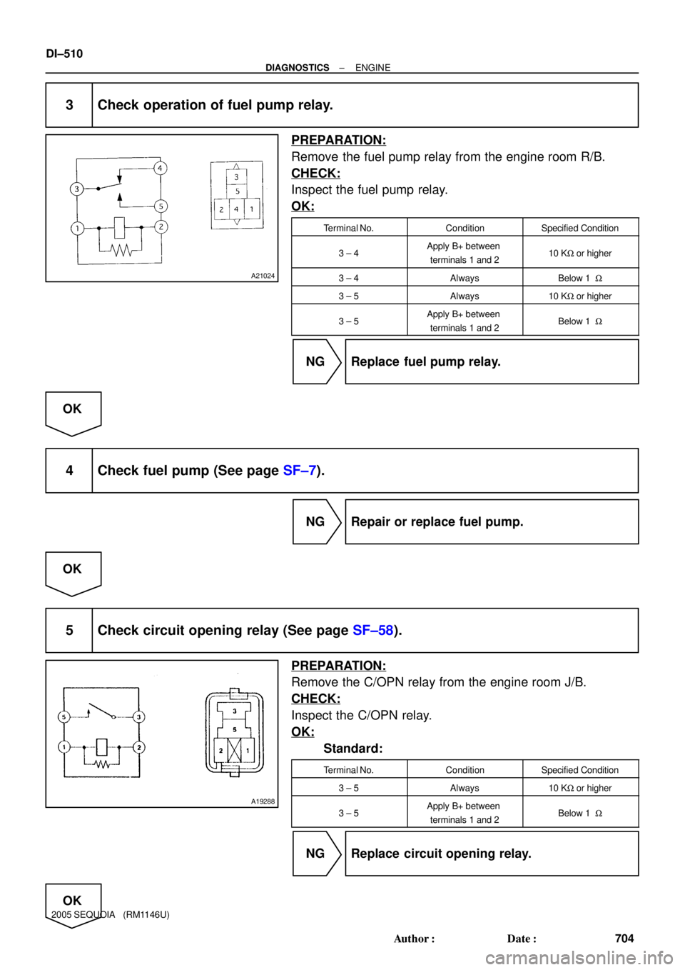
3 Check operation of fuel pump relay.
PREPARATION:
Remove the fuel pump relay from the engine room R/B.
CHECK:
Inspect the fuel pump relay.
OK:
Terminal No.ConditionSpecified Condition
3 ± 4Apply B+ between
terminals 1 and 210 KW or higher
3 ± 4AlwaysBelow 1 W
3 ± 5Always10 KW or higher
3 ± 5Apply B+ between
terminals 1 and 2Below 1 W
NG Replace fuel pump relay.
OK
4 Check fuel pump (See page SF±7).
NG Repair or replace fuel pump.
OK
5 Check circuit opening relay (See page SF±58).
PREPARATION:
Remove the C/OPN relay from the engine room J/B.
CHECK:
Inspect the C/OPN relay.
OK:
Standard:
Terminal No.ConditionSpecified Condition
3 ± 5Always10 KW or higher
3 ± 5Apply B+ between
terminals 1 and 2Below 1 W
NG Replace circuit opening relay.
OK
Page 713 of 4323
B17411FC (+)E4
± DIAGNOSTICSENGINE
DI±511
705 Author�: Date�:
2005 SEQUOIA (RM1146U)
6 Check for open in harness and connector between circuit opening relay and fuel
pump, and fuel pump and body ground (See page IN±35).
NG Repair or replace harness or connector.
OK
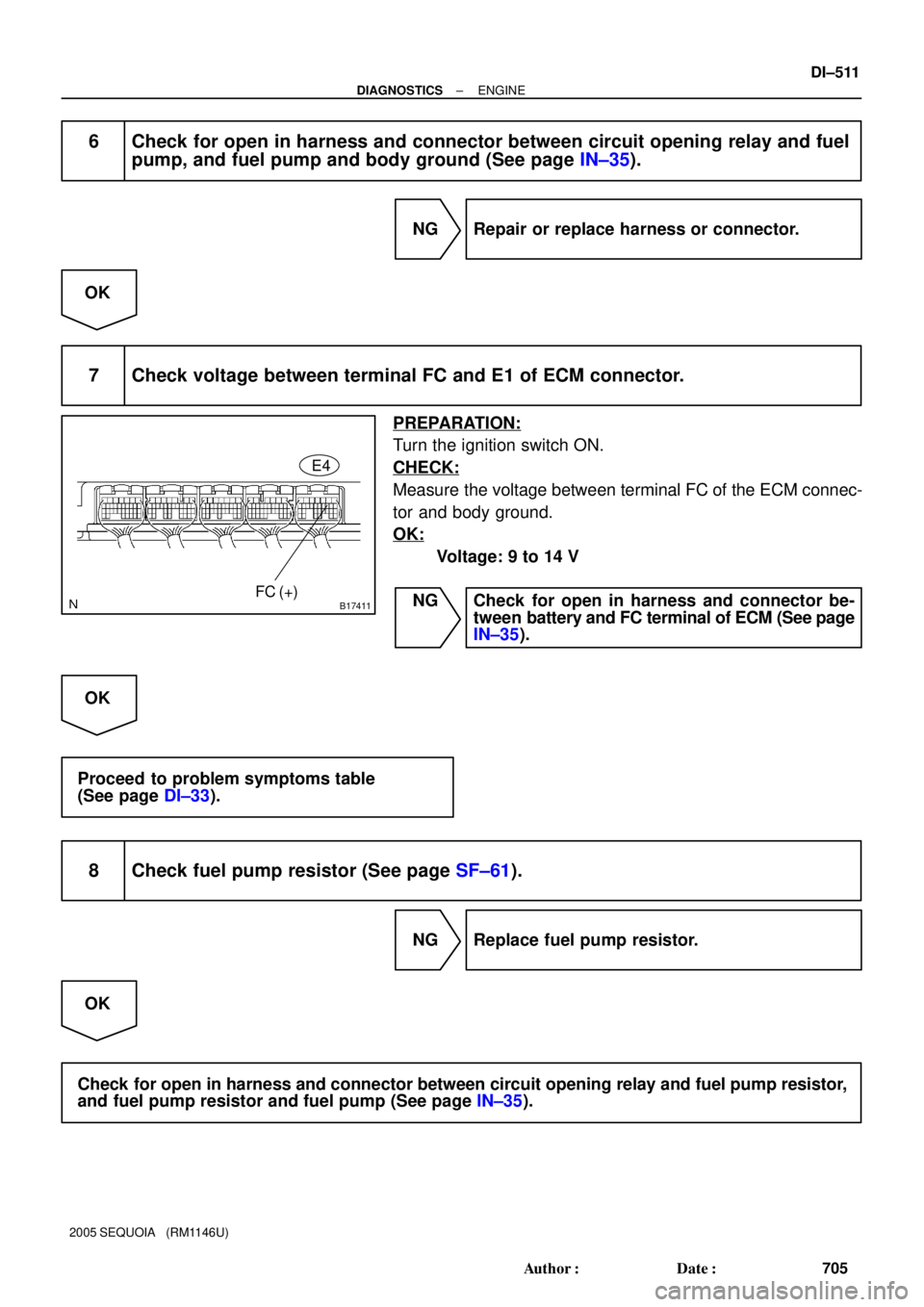
7 Check voltage between terminal FC and E1 of ECM connector.
PREPARATION:
Turn the ignition switch ON.
CHECK:
Measure the voltage between terminal FC of the ECM connec-
tor and body ground.
OK:
Voltage: 9 to 14 V
NG Check for open in harness and connector be-
tween battery and FC terminal of ECM (See page
IN±35).
OK
Proceed to problem symptoms table
(See page DI±33).
8 Check fuel pump resistor (See page SF±61).
NG Replace fuel pump resistor.
OK
Check for open in harness and connector between circuit opening relay and fuel pump resistor,
and fuel pump resistor and fuel pump (See page IN±35).
Page 774 of 4323

2. ACTIVE TEST
HINT:
Performing the ACTIVE TEST using the hand±held tester allows the relay, VSV, actuator an")
DI±572
± DIAGNOSTICSAUTOMATIC TRANSMISSION
766 Author�: Date�:
2005 SEQUOIA (RM1146U)
2. ACTIVE TEST
HINT:
Performing the ACTIVE TEST using the hand±held tester allows the relay, VSV, actuator and so on to oper-
ate without parts removal. Performing the ACTIVE TEST as the first step of troubleshooting is one method
to shorten labor time.
It is possible to display the DATA LIST during the ACTIVE TEST.
(a) Warm up the engine.
(b) Turn the ignition switch off.
(c) Connect the hand±held tester to the DLC3.
(d) Turn the ignition switch to the ON position.
(e) Turn on the tester.
(f) Select the item ºDIAGNOSIS / ENHANCED OBD II / ACTIVE TESTº.
(g) According to the display on the tester, perform the ºACTIVE TESTº.
ItemTest DetailsDiagnostic Note
SHIFT
[Test Details]
Operate the shift solenoid valve and set each shift position by yourself.
[Vehicle Condition]
Less than 50 km/h (31 mph)
[Others]
�Press º"º button: Shift up
�Press ºuº button: Shift down
Possible to check the operation of
the shift solenoid valves.
LOCK UP
[Test Details]
Control the shift solenoid SLU to set the automatic transmission to the
lock±up condition.
[Vehicle Condition]
�Throttle valve opening angle: Less than 35 %
�Vehicle Speed: 60 km/h (37 mph) or more
Possible to check the SLU opera-
tion.
LINE PRESS UP *
[Test Details]
Operate the shift solenoid SLT and raise the line pressure.
[Vehicle Condition]
�Vehicle Stopped.
�IDL: ON
[HINT]
OFF: Line pressure up (When the active test of ºControl the Line Pres-
sure Upº is performed, the ECM commands the SLT solenoid to turn
off).
ON: No action (normal operation)
±
*: ºLINE PRESS UPº in the ACTIVE TEST is performed to check the line pressure changes by connecting
the SST to the automatic transaxle, which is used in the HYDRAULIC TEST (See page DI±540) as well.
HINT:
The pressure values in ACTIVE TEST and HYDRAULIC TEST are different from each other.
Page 780 of 4323
D14218
ECM
R
D
2 3 E78
STAR/NSW
11
E5
E521
E519
E510 J52
J52
J52
J52
J52
J52 J/C
J51
J51
J51
J51
J51
J51B
L±Y
B±Y
W±R
L
LG LGL W±RB±YL±Y
L±R
L±R
B±Y W±L
W BG±R* G±R P
PL
RL
NL
DL
2L
LL IG49
1D 1C
IPOGAUGE
IG1
AM1 74
8
7
1C
1L16AM1
2 1 ALT
BatteryF10
FL BlockCowl Side J/B LHI18
Ignition SW Cowl Side J/B RHTo 4WD Control ECU
To Translate ECU To Starter RelayP1
Park/Neutral Position SW
*: 4WD 21 N
8 54
5
6
1
9
7
3
8AEG GF HA H
C C
F
E
2
RB DI±578
± DIAGNOSTICSAUTOMATIC TRANSMISSION
772 Author�: Date�:
2005 SEQUOIA (RM1146U)
WIRING DIAGRAM