Page 268 of 4323

MONITOR DESCRIPTION
After the ECM sends the ºtargetº duty±cycle signal to the OCV (Oil Control Valve), the ECM monitors the")
DI±74
± DIAGNOSTICSENGINE
268 Author�: Date�:
2005 SEQUOIA (RM1146U)
MONITOR DESCRIPTION
After the ECM sends the ºtargetº duty±cycle signal to the OCV (Oil Control Valve), the ECM monitors the
OCV current to establish an ºactualº duty±cycle. When the actual duty±cycle ratio varies from the target
duty±cycle, the ECM sets a DTC.
MONITOR STRATEGY
RltdDTCP0010VVT oil control valve bank 1 range checkRelated DTCsP0020VVT oil control valve bank 2 range check
Required sensors/componentsOCV
Frequency of operationContinuous
Duration1 sec.
MIL operationImmediate
Sequence of operationNone
TYPICAL ENABLING CONDITIONS
ItSpecificationItemMinimumMaximum
The monitor will run whenever this DTC is
not presentSee page DI±18
Battery voltage11 V13 V
Target duty ratio±70%
StarterOFF
Current cut statusNot cut
TYPICAL MALFUNCTION THRESHOLDS
Detection CriteriaThreshold
Either of the following conditions is met:Condition 1 or 2
1. Output signal duty for OCVOutput duty ratio is 100% (always ON) but target duty ratio is less than 70%
2. Output signal duty for OCVOutput duty is 3% or less despite the ECM supplying current to the OCV
COMPONENT OPERATING RANGE
ParameterStandard Value
Output signal duty for OCVºMore than 3%º and ºless than 100%º
Page 269 of 4323
A07621A09776
1
2L±W
P±LOC1+
OC1±
OC2+
OC2± 17
L±B
R±L 1
2E6 C13
OCV (Bank 1)
C14
OCV (Bank 2)ECM
16
15
14 E6
E6
E6
± DIAGNOSTICSENGINE
DI±75
269 Author�: Date�:
2005 SEQUOIA (RM1146U)
WIRING DIAGRAM
INSPECTION PROCEDURE
HINT:
�If DTC P0010 displayed, check left bank OCV circuit.
�If DTC P0020 displayed, check right bank OCV circuit.
�Read freeze frame data using hand±held tester. Because freeze frame records the engine conditions
when the malfunction is detected. When troubleshooting, it is useful for determining whether the ve-
hicle was running or stopped, the engine was warmed up or not, the air±fuel ratio was lean or rich, etc.
at the time of the malfunction.
Page 270 of 4323
A31449A23511
Valve Battery ±
Battery +
DI±76
± DIAGNOSTICSENGINE
270 Author�: Date�:
2005 SEQUOIA (RM1146U)
1 Check OCV circuit.
PREPARATION:
(a) Connect the hand±held tester to the DLC3.
(b) Start the engine and warm it up.
(c) Turn the ignition switch to ON and turn the hand±held tester ON.
CHECK:
(a) Select the item: DIAGNOSIS / ENHANCED OBD II / ACTIVE TEST / VVT CTRL B1 or VVT CTRL B2.
(b) Using the hand±held tester, operate the OCV and check the engine speed.
OK:
Standard:
Tester OperationSpecified Condition
OCV is OFFNormal engine speed
OCV is ONRough idle or engine stall
OK Check for intermittent problems
(See page DI±11).
NG
2 Check operation of OCV.
PREPARATION:
(a) Start the engine and warmed it up.
(b) Disconnect the OCV connector.
(c) Apply battery positive voltage between the terminals of
the OCV.
CHECK:
Check the engine speed.
OK:
Rough idle or engine stalled.
NG Replace OCV.
OK
Page 271 of 4323
A02397
OCV Signal Waveform
1 msec./Division5 V/
Division
GND
(A) (A) (A)
B17414ECM ConnectorE6
OC1+
OC1±
OC2+OC2±
E1
± DIAGNOSTICSENGINE
DI±77
271 Author�: Date�:
2005 SEQUOIA (RM1146U)
3 Check voltage between terminals OC1+ and OC1±, OC2+ and OC2± of ECM con-
nector.
CHECK:
(a) Inspection using the oscilloscope.
(b) During idling, check the waveform between the specified
terminals of the E6 ECM connector.
HINT:
The waveform frequency (A) is lengthened as the engine speed
becomes higher.
OK:
Standard:
The correct waveform is as shown.
NG Replace ECM (See page SF±80).
OK
Page 272 of 4323

4 Check for open and short in harn")
A23673
Wire Harness Side
C13
OCV Connector C14
B17414ECM ConnectorE6
OC1+
OC1±
OC2+OC2±
E1
DI±78
± DIAGNOSTICSENGINE
272 Author�: Date�:
2005 SEQUOIA (RM1146U)
4 Check for open and short in harness and connector between OCV and ECM.
PREPARATION:
(a) Disconnect the C13 or C14 OCV connector.
(b) Disconnect the E6 ECM connector.
CHECK:
(a) Check for resistance between the wire harness side con-
nectors.
OK:
Standard (Check for open):
Symbols (Terminal No.)Specified condition
OCV (C14±1) ± OC1+ (E6±17)Below 1 W
OCV (C14±2) ± OC1± (E6±16)Below 1 W
OCV (C13±1) ± OC2+ (E6±15)Below 1 W
OCV (C13±2) ± OC2± (E6±14)Below 1 W
Standard (Check for short):
Symbols (Terminal No.)Specified condition
OCV (C14±1) or OC1+ (E6±17) ± E1 (E6±1)10 kW or higher
OCV (C14±1) or OC1± (E6±16) ± E1 (E6±1)10 kW or higher
OCV (C13±1) or OC2+ (E6±15) ± E1 (E6±1)10 kW or higher
OCV (C13±1) or OC2± (E6±14) ± E1 (E6±1)10 kW or higher
NG Repair or replace harness or connector.
OK
Check for intermittent problems
(See page DI±11).
Page 274 of 4323

MONITOR STRATEGY
P0011VVT system advance (Bank 1)
RltdDTCP0012VVT system retard (Bank 1)Related DTCsP0021VVT system advance (Ba")
DI±80
± DIAGNOSTICSENGINE
274 Author�: Date�:
2005 SEQUOIA (RM1146U)
MONITOR STRATEGY
P0011VVT system advance (Bank 1)
RltdDTCP0012VVT system retard (Bank 1)Related DTCsP0021VVT system advance (Bank 2)
P0022VVT system retard (Bank 2)
Main sensors/componentsCamshaft position sensor
Required sensors/componentsRelated sensors/componentsEngine coolant temperature sensor,
Crankshaft position sensor
Frequency of operationOnce per drive cycle
Duration10 sec.
MIL operationP0011, P0021: Immediate
P0012, P0022: 2 driving cycles
Sequence of operationNone
TYPICAL ENABLING CONDITIONS
ItSpecificationItemMinimumMaximum
The monitor will run whenever these
DTCs are not presentSee page DI±18
Battery voltage11 V±
Throttle position learningCompleted
Engine RPM400 rpm4,000 rpm
Engine coolant temperature75�C (167�F)100�C (212�F)
TYPICAL MALFUNCTION THRESHOLDS
Detection CriteriaThreshold
Deviation of valve timingMore than 5�CA
OCV activation63 times or more
Response of valve timing1 sec./1�CA or more
WIRING DIAGRAM
Refer to DTCs P0010 on page DI±73.
INSPECTION PROCEDURE
HINT:
�Bank 1 refers to bank that includes cylinder No. 1.
�Bank 2 refers to bank that does not include cylinder No. 1.
�If DTC P0011, P0012 is displayed, check the bank 1 VVT system.
�If DTC P0021, P0022 is displayed, check the bank 2 VVT system.
�Read freeze frame data using the hand±held tester. Freeze frame data records the engine conditions
when a malfunction is detected. When troubleshooting, it is useful for determining whether the vehicle
was running or stopped, the engine was warmed up or not, the air±fuel ratio was lean or rich, etc. at
the time of the malfunction.
Page 275 of 4323

1 Check operation of OCV.
PREPARATION:
(a) Connect the hand±held tester to the DLC3.
(b) Start the engine and warm it up.
(c)")
± DIAGNOSTICSENGINE
DI±81
275 Author�: Date�:
2005 SEQUOIA (RM1146U)
1 Check operation of OCV.
PREPARATION:
(a) Connect the hand±held tester to the DLC3.
(b) Start the engine and warm it up.
(c) Turn the ignition switch to ON and turn the hand±held tester ON.
CHECK:
(a) Select the item: DIAGNOSIS / ENHANCED OBD II / ACTIVE TEST / VVT CTRL B1 or VVT CTRL B2.
(b) Using the hand±held tester, operate the OCV and check the engine speed.
OK:
Standard:
Tester OperationSpecified Condition
OCV is OFFNormal engine speed
OCV is ONRough idle or engine stall
OK VVT system is OK.*
*: DTC P0011, P0012, P0021 or P0022 is also output when a
foreign object is detected in some parts of the system in the en-
gine oil, and then the system returns to normal in a short time.
As ECM is controlled to eject a foreign object, there is no prob-
lem on the VVT. There is also no problem on the VVT as the oil
filter should catch the foreign object in the engine oil.
NG
2 Check valve timing (See page EM±23).
NG Adjust valve timing.
OK
Page 276 of 4323
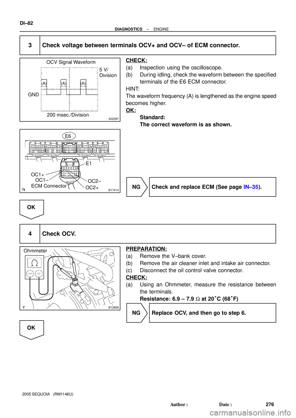
A02397
OCV Signal Waveform
200 msec./Division5 V/
Division
GND
(A) (A) (A)
B17414ECM ConnectorE6
OC1+
OC1±
OC2+OC2±
E1
B12806
Ohmmeter
DI±82
± DIAGNOSTICSENGINE
276 Author�: Date�:
2005 SEQUOIA (RM1146U)
3 Check voltage between terminals OCV+ and OCV± of ECM connector.
CHECK:
(a) Inspection using the oscilloscope.
(b) During idling, check the waveform between the specified
terminals of the E6 ECM connector.
HINT:
The waveform frequency (A) is lengthened as the engine speed
becomes higher.
OK:
Standard:
The correct waveform is as shown.
NG Check and replace ECM (See page IN±35).
OK
4 Check OCV.
PREPARATION:
(a) Remove the V±bank cover.
(b) Remove the air cleaner inlet and intake air connector.
(c) Disconnect the oil control valve connector.
CHECK:
(a) Using an Ohmmeter, measure the resistance between
the terminals.
Resistance: 6.9 ± 7.9 W at 20°C (68°F)
NG Replace OCV, and then go to step 6.
OK