Page 2050 of 4323
DI±1848
± DIAGNOSTICSPASSENGER DOOR CONTROL SYSTEM
2042 Author�: Date�:
2005 SEQUOIA (RM1146U)
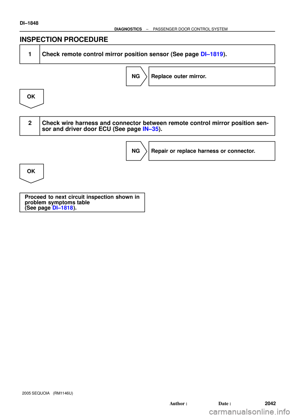
INSPECTION PROCEDURE
1 Check remote control mirror position sensor (See page DI±1819).
NG Replace outer mirror.
OK
2 Check wire harness and connector between remote control mirror position sen-
sor and driver door ECU (See page IN±35).
NG Repair or replace harness or connector.
OK
Proceed to next circuit inspection shown in
problem symptoms table
(See page DI±1818).
Page 2249 of 4323
DIDAG±01
I28272
AVC±LAN:
Stereo Component
Amplifier Assy� Radio Receiver Assy
(w/o Navigation)
� Radio and Navigation Assy
(w/ Navigation)
Rear Seat Audio Controller
: AVC LAN
± DIAGNOSTICSREAR SEAT AUDIO SYSTEM
DI±2047
2241 Author�: Date�:
2005 SEQUOIA (RM1146U)
SYSTEM DESCRIPTION
1. OUTLINE
(a) Rear Seat Audio (RSA) system, which consists of a rear seat audio controller and a remote controller
(switch assy), enables the rear seat occupants to use headphones to listen simultaneously to a differ-
ent audio mode than the one that is selected in the front audio head unit.
2. COMMUNICATION SYSTEM
Page 2252 of 4323

PROBLEM SYMPTOMS TABLE
RSA SYSTEM
SymptomSuspected AreasSee page
RSA system cannot be powered.1. P")
DIDAK±01
DI±2050
± DIAGNOSTICSREAR SEAT AUDIO SYSTEM
2244 Author�: Date�:
2005 SEQUOIA (RM1146U)
PROBLEM SYMPTOMS TABLE
RSA SYSTEM
SymptomSuspected AreasSee page
RSA system cannot be powered.1. Power source circuit (rear seat controller assy)DI±2058
Quality of sound from wireless headphone is poor or no sound
can be heard.
1. Power source circuit (rear seat controller assy)
2. Mute signal circuit (to rear seat audio controller)
3. Sound signal circuit (to rear seat audio controller)
4. Rear seat audio controllerDI±2058
DI±2066
DI±2070
±
Quality of sound from headphone connected to headphone termi-
nal is poor or no sound can be heard.
1. Power source circuit (rear seat controller assy)
2. Mute signal circuit (to rear seat audio controller)
3. Sound signal circuit (Rear seat audio controller ± head-
phone terminal)
4. Sound signal circuit (Radio receiver assy / radio and
navigation assy ± rear seat audio controller)DI±2058
DI±2066
DI±2073
DI±2070
REMOTE CONTROL
SymptomSuspected AreasSee page
A remote control system does not operate.
1. Power source circuit (rear seat controller assy)
2. A remote control system does not operate
3. AVC±LAN circuitDI±2058
DI±2076
DI±2061
Page 2278 of 4323
DI±2076
± DIAGNOSTICSREAR SEAT AUDIO SYSTEM
2270 Author�: Date�:
2005 SEQUOIA (RM1146U)
Remote control system does not operate
INSPECTION PROCEDURE
1 Check malfunction symptoms.
CHECK:
Check obstruction.
Check that there are no obstructions between the switch assy and the infrared ray light emission por-
tion of the rear seat audio controller.
OK:
No obstructions
NG Remove the obstructions.
OK
2 Check battery (Switch assy).
CHECK:
Check battery.
Check that the dry±cell battery used for the switch assy is not dead.
OK:
It is not dead.
NG Replace dry±cell battery.
OK
DIDAR±01
Page 2283 of 4323

SYSTEM DESCRIPTION
1. Outline
�As a unique feature of Rear Seat Entertainment (RSE) system")
DIDAV±01
± DIAGNOSTICSREAR SEAT ENTERTAINMANT SYSTEM
DI±2081
2275 Author�: Date�:
2005 SEQUOIA (RM1146U)
SYSTEM DESCRIPTION
1. Outline
�As a unique feature of Rear Seat Entertainment (RSE) system, the front and rear seat occupants can
enjoy different audio±visual modes at the same time. Thus, this system offers enhanced entertainment
to the rear seat occupants.
�The rear seat occupants can control the audio±visual modes with the remote controller (switch assy),
and listen to audio by using wired or wireless headphones.
�The RSE system is controlled by the multi±display controller, and the communication among the audio
head unit, rear display assembly, and DVD player is established via an AVC±LAN (Audio Visual Com-
munication±Local Area Network).
2. Function of Main Component
Television Display Assy
�Displays DVD and video images in accordance with video signals from the RSE ECU.
�Receives signals from the remote controller and outputs them to the RSE ECU.
�Outputs audio signals to the wireless headphones in the form of infrared signals.
�Displays the audio±visual control screen.
�Displays the adjustment screen.
�Displays the diagnosis screen.
�The diagnosis screen appears when the diagnosis mode is started on the audio head unit.
Audio Head Unit
w/ Navigation system:
Radio and navigation assy
w/o Navigation system:
Radio receiver assy
�Outputs audio signals to the RSE ECU and the stereo component amplifier.
�Outputs a request to the RSE ECU to start the diagnosis mode.
RSE ECU (Multi±display Controller)
�Processes video and audio signals from the DVD player and video player and audio signals from the
audio head unit, and outputs them to the television display assembly and headphone terminals.
�Controls the distribution of the audio±visual mode to the front (audio head unit) and the rear (RSE).
Remote Controller (Switch Assy)Outputs various control signals of the RSE system to the television display assembly in the form of in-
frared signals.
Wireless Headphone
�Receives the audio signals from the television display assembly in the form of infrared signals.
�Volume adjustment of the wireless headphone can be done by using the volume equipped on the wire-
less headphone.
Headphone Terminal�Outputs audio signals to the wired headphones that are connected.
�Adjusts the volume of the wired headphones in accordance with volume control.
VTR TerminalThis terminal is for connecting the video player's video and audio output terminals.
Page 2287 of 4323
DIDAY±01
I28281
ºDiagnosis MENUº
to section
Press ENTER on
remote control
The entire screen is changed
to the color which is selected
in the color bar check mode. Select color by
remote control
operation
± DIAGNOSTICSREAR SEAT ENTERTAINMANT SYSTEM
DI±2085
2279 Author�: Date�:
2005 SEQUOIA (RM1146U)
DISPLAY CHECK MODE
DISPLAY CHECK MODE
HINT:
�Illustrations may differ from the actual vehicle depending on the device settings and options. There-
fore, some detailed areas may not be shown exactly the same as on the actual vehicle.
�Display check mode is operated as follows.
Page 2288 of 4323

I28282
*2 *1
I28283
The entire screen is
changed to the color
which is selected in
the color bar check
mode.
Press ENTER
on remote
control Select color by
remote control
operation
I28284
DI±2086
± DIAGNOSTICSREAR SEAT ENTERTAINMANT SYSTEM
2280 Author�: Date�:
2005 SEQUOIA (RM1146U)
(a) Display Check Mode
DisplayContents
Color Bar Check/*1Color display is checked.
Remote Commander/*2Operating condition of remote command-
er display is checked.
HINT:
In Display Check Mode, above checks can be performed.
(b) Display Color Bar Check
(1) Start the Diagnosis System (See page DI±2097).
(2) Select ºMENUº.
(3) Select ºDisplay Checkº.
(4) Select ºColor Bar Checkº.
(5) Make sure that each color name is corresponding
to each color on the bar.
HINT:
Select Black, Red, Green, Blue, White and Stripe to display se-
lected colors and stripe on the entire screen.
(6) Compare the color with the Color Bar Check, and
make sure that the color is the same.
(c) Display Remote Commander Check
(1) Start the Diagnosis system (See page DI±2097).
(2) Select ºMENUº.
(3) Select ºDisplay Checkº.
(4) Select ºRemote Commanderº.
(5) Press each switch and make sure that it corre-
sponds to the display on the screen.
Page 2291 of 4323
 Quality of sound from wireless headphone is poor or no sound
can be heard (radio sound only).
1. w/o")
± DIAGNOSTICSREAR SEAT ENTERTAINMANT SYSTEM
DI±2089
2283 Author�: Date�:
2005 SEQUOIA (RM1146U) Quality of sound from wireless headphone is poor or no sound
can be heard (radio sound only).
1. w/o Navigation System:
Sound signal circuit (multi±display controller sub±assy ±
radio receiver assy)
w/ Navigation System:
Sound signal circuit (multi±display controller sub±assy ±
radio and navigation assy)
2. Multi±display controller sub±assy
3. w/o Navigation System:
Radio receiver assy
4. w/ Navigation System:
Radio and navigation assy
DI±2123
DI±2125
±
±
±
Quality of sound from headphone connected is poor or no sound
can be heard (radio sound only).
1. w/o Navigation System:
Sound signal circuit (multi±display controller sub±assy ±
radio receiver assy)
w/ Navigation System:
Sound signal circuit (multi±display controller sub±assy ±
radio and navigation assy)
2. Multi±display controller sub±assy
3. w/o Navigation System:
Radio receiver assy
4. w/ Navigation System:
Radio and navigation assy
DI±2123
DI±2125
±
±
±
REMOTE CONTROL
SymptomSuspect AreaSee page
A remote control system does not operate.
1. A remote control system does not operate
2. Remote commander check of display check mode
3. Power source circuit (multi±display controller sub±assy)
4. Power source circuit (television display assy)
5. AVC±LAN circuitDI±2157
DI±2085
DI±2110
DI±2107
DI±2139