Page 874 of 4323

DTC P2757Torque Converter Clutch Pre")
D14175
G23415D14176
Lock±up
Operation
Pressure
Current Flow to Solenoid DI±672
± DIAGNOSTICSAUTOMATIC TRANSMISSION
866 Author�: Date�:
2005 SEQUOIA (RM1146U)
DTC P2757Torque Converter Clutch Pressure Control Solenoid
Performance(Shift Solenoid Valve SLU)
SYSTEM DESCRIPTION
The ECM uses the signals from the throttle position sensor, Air±
flow meter, turbine (input) speed sensor, output speed sensor
and crankshaft position sensor to monitor the engagement
condition of the lock±up clutch.
Then the ECM compares the engagement condition of the
lock±up clutch with the lock±up schedule in the ECM memory
to detect a mechanical problems of the shift solenoid valve
SLU, valve body and torque converter clutch.
DTC No.DTC Detection ConditionTrouble Area
P2757
Lock±up does not occur when driving in the lock±up range
(normal driving at 80 km/h [50 mph]), or lock±up remains ON
in the lock±up OFF range.
(2±trip detection logic)�Shift solenoid valve SLU remains open or closed
�Valve body is blocked
�Torque converter clutch
�Automatic transmission (clutch, brake or gear, etc.)
�Line pressure is too low
DIDJO±01
Page 875 of 4323

MONITOR DESCRIPTION
Torque converter lock±up is controlled by the ECM based on the turbine (input) speed sens")
± DIAGNOSTICSAUTOMATIC TRANSMISSION
DI±673
867 Author�: Date�:
2005 SEQUOIA (RM1146U)
MONITOR DESCRIPTION
Torque converter lock±up is controlled by the ECM based on the turbine (input) speed sensor NT, output
speed sensor SP2, engine rpm, engine load, engine temperature, vehicle speed, transmission temperature,
and gear selection. The ECM determines the lock±up status of the torque converter by comparing the engine
rpm (NE) to the input turbine rpm (NT). The ECM calculates the actual transmission gear by comparing input
turbine rpm (NT) to output shaft rpm (SP2). When conditions are appropriate, the ECM requests ºlock±upº
by applying control voltage to the shift solenoid SLU. When the SLU is turned on, it applies pressure to the
lock±up relay valve and locks the torque converter clutch.
If the ECM detects no lock±up after lock±up has been requested or if it detects lock±up when it is not re-
quested, the ECM interprets this as a fault in the shift solenoid valve SLU or lock±up system performance.
The ECM will turn on the MIL and store the DTC.
Example:
When any of the following is met, the system judges it as a malfunction.
(a) There is a difference in rotation between the input side (engine speed) and output side (input turbine
speed) of the torque converter when the ECM commands lock±up.
(Engine speed is at least 70 rpm greater than input turbine speed.)
(b) There is no difference in rotation between the input side (engine speed) and output side (input turbine
speed) of the torque converter when the ECM commands lock±up off.
(The difference between engine speed and input turbine speed is less than 35 rpm.)
MONITOR STRATEGY
RltdDTCP2757Shift solenoid valve SLU/OFF malfunctionRelated DTCsP2757Shift solenoid valve SLU/ON malfunction
MainShift solenoid valve SLU
Required sensors/ComponentsSubValve body, Vehicle speed sensor, Throttle position sensor, Speed sensor
(NT), Speed sensor (NO)
Frequency of operationContinuous
OFF malfunction (A)2 sec.
DurationOFF malfunction (B)0.4 sec.Duration
ON malfunction1.8 sec.
MIL operation2 driving cycles
Sequence of operationNone
TYPICAL ENABLING CONDITIONS
ItSpecificationItemMinimumMaximum
All:
Turbine speed sensor circuitNot circuit malfunction
Output speed sensor circuitNot circuit malfunction
Shift solenoid valve S1 circuitNot circuit malfunction
Shift solenoid valve S2 circuitNot circuit malfunction
Shift solenoid valve SR circuitNot circuit malfunction
Torque converter clutch pressure control
solenoid circuitNot circuit malfunction
KCS sensor circuitNot circuit malfunction
ETCS (Electric throttle control system)Not system down
Transmission rangeºDº
Page 876 of 4323
 ECT (Engine coolant temperature)
40°C (104°F) or more±
Spark advance from Max. retard timing by
KCS control")
DI±674
± DIAGNOSTICSAUTOMATIC TRANSMISSION
868 Author�: Date�:
2005 SEQUOIA (RM1146U) ECT (Engine coolant temperature)
40°C (104°F) or more±
Spark advance from Max. retard timing by
KCS control0° CA or more±
EngineStarting
ECM selected gear4th or 5th
Vehicle speed25 km/h (15.5 mph) or more±
Shift solenoid valve S1 circuitNot on malfunction
Shift solenoid valve S2 circuitNot on malfunction
Shift solenoid valve SL2 circuitNot on malfunction
1±2 Shift valveNot on malfunction
Transfer neutral position switchOFF
Transfer rangeºHIGHº*1
Transfer range ºHIGHº *1 (This condition is applied only 4WD)
*1 Following conditions met
Vehicle speed sensor circuitNot circuit malfunction
Output shaft speed sensor circuitNot circuit malfunction
Transfer output speed143 rpm or more±
NO/NOtf (Transfer input speed/Transfer
output speed)0.9 to 1.1
OFF malfunction (A)
ECM lock±up commandON
(SLU pressure: 513kpa or more)
Vehicle speed±Less than 100 km/h (62.2 mph)
OFF malfunction (B)
ECM selected gear2nd
Vehicle speed2 km/h (1.2 mph) or more±
Output speed2nd " 1st down shift point or more±
Throttle valve opening angle7.0% or more at 2,000 rpm
(Conditions vary with engine speed)±
ON malfunction
ECM lock±up commandOFF
(SLU pressure: less than 4kpa)
Throttle valve opening angle9% or more±
Vehicle speed±Less than 60 km/h (37.3 mph)
Page 882 of 4323

DTC P2759Torque Converter Clu")
Current flow to solenoid
Lock±up
Operation
Pressure
BE4056D00160
1 cycle ON
OFF DI±680
± DIAGNOSTICSAUTOMATIC TRANSMISSION
874 Author�: Date�:
2005 SEQUOIA (RM1146U)
DTC P2759Torque Converter Clutch Pressure Control Solenoid
Control Circuit Electrical(Shift Solenoid Valve SLU)
CIRCUIT DESCRIPTION
The amount of current flow to the solenoid is controlled by the
(*) duty ratio of the ECM output signal. The higher the duty ratio
becomes, the higher the lock±up hydraulic pressure becomes
during the lock±up operation.
(*) Duty Ratio
The duty ratio is the ratio of the period of continuity in one cycle.
For example, if A is the period of continuity in one cycle, and B
is the period of non±continuity, then
Duty Ratio = A/(A + B) x 100 (%)
DTC No.DTC detection conditionTrouble Area
P2759Open or short is detected in shift solenoid valve SLU circuit for
1 second or more while driving (1±trip detection logic).�Open or short in shift solenoid valve SLU circuit
�Shift solenoid valve SLU
�ECM
MONITOR DESCRIPTION
When an open or short in a shift solenoid valve (SLU) circuit is detected, the ECM determines there is a mal-
function. The ECM will turn on the MIL and store this DTC.
MONITOR STRATEGY
Related DTCsP2759Shift solenoid valve SLU/Range check
Required sensors/ComponentsShift solenoid valve SLU
Frequency of operationContinuous
Duration1 sec.
MIL operationImmediate
Sequence of operationNone
DIDJP±01
Page 887 of 4323

DTC P2772 Transfer L4 SW Circuit
CIRCUIT DESCRIPTION
The ECM detects the signal from the transfer L4 position")
± DIAGNOSTICSAUTOMATIC TRANSMISSION
DI±685
879 Author�: Date�:
2005 SEQUOIA (RM1146U)
DTC P2772 Transfer L4 SW Circuit
CIRCUIT DESCRIPTION
The ECM detects the signal from the transfer L4 position switch.
This DTC indicates that the transfer L4 position switch remains ON.
DTC No.DTC Detecting ConditionTrouble Area
P2772
Transfer L4 position switch remains ON while vehicle running
under conditions for 18 seconds or more (1±trip detection log-
ic)
(a) Output shaft speed 3000 rpm or less
(b) Transfer shift position is H�Short in transfer L4 position switch circuit
�Transfer L4 position switch
�4WD control ECU
�ECM
MONITOR DESCRIPTION
The ECM monitors the transfer±case L4 position switch to determine when the transfer±case L4 gear is en-
gaged. If the transfer±case L4 gears remain engaged under the following conditions, the ECM will conclude
that there is a malfunction of the L4 position switch:
�L4 switch indicated that the L4 transfer±case gears are engaged.
�Transfer±case shifter is in the ºHº position.
�Transfer±case output shaft rpm is between 750 and 3,000 rpm.
�The specified time period has elapsed.
If all of the above conditions are detected, the ECM will conclude that there is a malfunction of the L4 switch,
and illuminate the MIL and store the DTC.
MONITOR STRATEGY
Related DTCsP2772Transfer L4 position switch/ON malfunction
Required sensors/ComponentsTransfer L4 position switch
Frequency of operationContinuous
DtiON malfunction (A)1.8 sec.DurationON malfunction (B)0.5 sec.
MIL operation1 driving cycle
Sequence of operationNone
TYPICAL ENABLING CONDITIONS
ItSpecificationItemMinimumMaximum
All:
Output speed sensor circuitNot circuit malfunction
Vehicle speed sensor circuitNot circuit malfunction
Transfer neutral position switchOFF
ON malfunction (A)
Output speed (Transfer output speed)1,000 to 3,000 rpm
ON malfunction (B)
Output speed (Transfer output speed)143 rpm or more±
DIDJQ±01
Page 898 of 4323
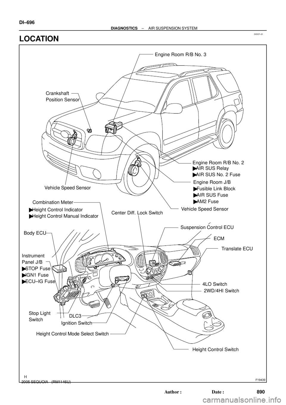
DIDCF±01
F19439
Crankshaft
Position SensorEngine Room R/B No. 3
Engine Room J/B
Instrument
Panel J/B
� STOP Fuse
� IGN1 Fuse
� ECU±IG Fuse
Stop Light
Switch
Combination Meter
Height Control Switch Body ECU
ECM Engine Room R/B No. 2
Suspension Control ECU
Translate ECU
4LO Switch
2WD/4HI Switch
Height Control Mode Select SwitchIgnition Switch � Height Control Indicator� Fusible Link Block
� AIR SUS Fuse
� AM2 Fuse
� Height Control Manual IndicatorCenter Diff. Lock Switch
DLC3
Vehicle Speed Sensor
Vehicle Speed Sensor
� AIR SUS Relay
� AIR SUS No. 2 Fuse DI±696
± DIAGNOSTICSAIR SUSPENSION SYSTEM
890 Author�: Date�:
2005 SEQUOIA (RM1146U)
LOCATION
Page 899 of 4323
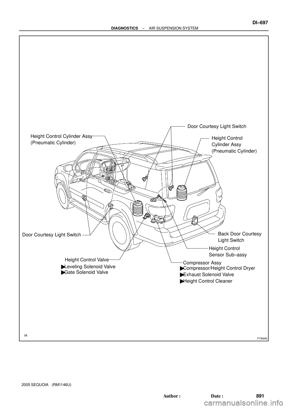
F19440
Height Control
Cylinder Assy
(Pneumatic Cylinder)
Height Control Valve Height Control Cylinder Assy
(Pneumatic Cylinder)
Door Courtesy Light Switch
� Leveling Solenoid Valve
� Gate Solenoid ValveDoor Courtesy Light Switch
� Compressor/Height Control Dryer
� Exhaust Solenoid Valve
� Height Control Cleaner
Height Control
Sensor Sub±assy
Compressor Assy
Back Door Courtesy
Light Switch
± DIAGNOSTICSAIR SUSPENSION SYSTEM
DI±697
891 Author�: Date�:
2005 SEQUOIA (RM1146U)
Page 900 of 4323
DIDCI±01
F19438
Height Control Sensor
Sub±assy
Height Control Mode
Select Switch
Body ECU
Stop Light Switch
Front Door Courtesy
Light Switch (Driver)
Front Door Courtesy
Light Switch
(Passenger)
Rear Door Courtesy
Light Switch (LH)
Rear Door Courtesy
Light Switch (RH)
Back Door Courtesy
Light SwitchCombination Meter
Leveling Solenoid Valve
AIR SUS Relay
DLC3
ECM
Translate ECU Compressor/
Height Control Dryer
Exhaust Solenoid Valve Height Control Valve
Compressor Assy Gate Solenoid Valve IG
BBAT
SBL2
SHRL
SGL2VN
HI
NR
LO
TD
UPSW
DWSW
Door
STPSLRR
SLRL
RC
RM+
RM±
SLEX
SIL
CANH
CANL
CANSuspension
Control ECU Height Control Switch
GND From IG SwitchFrom Battery
From
Battery DI±698
± DIAGNOSTICSAIR SUSPENSION SYSTEM
892 Author�: Date�:
2005 SEQUOIA (RM1146U)
SYSTEM DIAGRAM

Front Door Courtesy
Light Switch
(Passenger)")